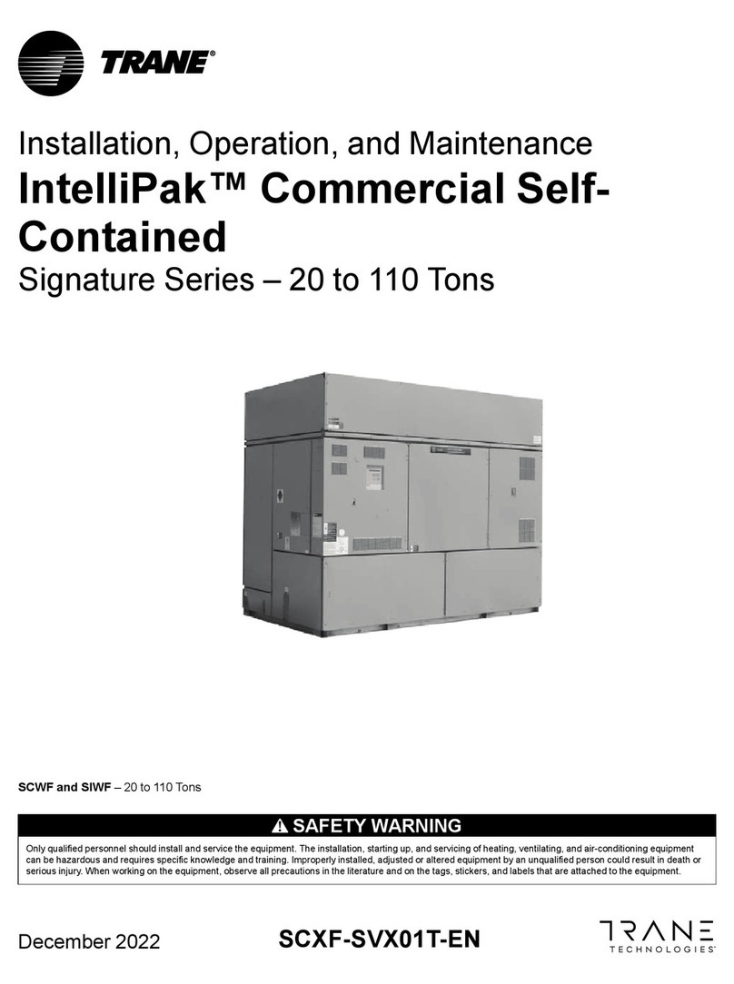
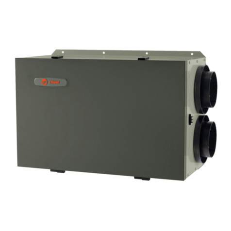
Trane Technologies HUV075 Installation and operating instructions

Horizontal Classroom Unit
Ventilator
Model HUV
Installation, Operation, and Maintenance
February 2023 UV-SVX004E-EN
Model Number: HUV - “C” and later Design Sequence 750 cfm to 2000 cfm
SAFETY WARNING
Only qualified personnel should install and service the equipment. The installation, starting up, and servicing of
heating, ventilating, and air-conditioning equipment can be hazardous and requires specific knowledge and training.
Improperly installed, adjusted or altered equipment by an unqualified person could result in death or serious injury.
When working on the equipment, observe all precautions in the literature and on the tags, stickers, and labels that are
attached to the equipment.

©2023 Trane UV-SVX004E-EN
Introduction
Read this manual thoroughly before operating or servicing this
unit.
Warnings, Cautions, and Notices
Safety advisories appear throughout this manual as required.
Your personal safety and the proper operation of this machine
depend upon the strict observance of these precautions.
Important Environmental Concerns
Scientific research has shown that certain man-made
chemicals can affect the earth’s naturally occurring
stratospheric ozone layer when released to the atmosphere. In
particular, several of the identified chemicals that may affect
the ozone layer are refrigerants that contain Chlorine, Fluorine
and Carbon (CFCs) and those containing Hydrogen, Chlorine,
Fluorine and Carbon (HCFCs). Not all refrigerants containing
these compounds have the same potential impact to the
environment. Trane advocates the responsible handling of all
refrigerants-including industry replacements for CFCs and
HCFCs such as saturated or unsaturated HFCs and HCFCs.
Important Responsible Refrigerant
Practices
Trane believes that responsible refrigerant practices are
important to the environment, our customers, and the air
conditioning industry. All technicians who handle refrigerants
must be certified according to local rules. For the USA, the
Federal Clean AirAct (Section 608) sets forth the requirements
for handling, reclaiming, recovering and recycling of certain
refrigerants and the equipment that is used in these service
procedures. In addition, some states or municipalities may
have additional requirements that must also be adhered to for
responsible management of refrigerants. Know the applicable
laws and follow them.
The three types of advisories are defined as follows:
WARNING Indicates a potentially hazardous
situation which, if not avoided, could
result in death or serious injury.
CAUTION Indicates a potentially hazardous
situation which, if not avoided, could
result in minor or moderate injury. It could
also be used to alert against unsafe
practices.
NOTICE Indicates a situation that could result in
equipment or property-damage only
accidents.
WARNING
Proper Field Wiring and Grounding
Required!
Failure to follow code could result in death or serious
injury. All field wiring MUST be performed by qualified
personnel. Improperly installed and grounded field
wiring poses FIRE and ELECTROCUTION hazards. To
avoid these hazards, you MUST follow requirements for
field wiring installation and grounding as described in
NEC and your local/state/national electrical codes.
WARNING
Personal Protective Equipment (PPE)
Required!
Failure to wear proper PPE for the job being undertaken
could result in death or serious injury. Technicians, in
order to protect themselves from potential electrical,
mechanical, and chemical hazards, MUST follow
precautions in this manual and on the tags, stickers,
and labels, as well as the instructions below:
• Before installing/servicing this unit, technicians
MUST put on all PPE required for the work being
undertaken (Examples; cut resistant gloves/sleeves,
butyl gloves, safety glasses, hard hat/bump cap, fall
protection, electrical PPE and arc flash clothing).
ALWAYS refer to appropriate Safety Data Sheets
(SDS) and OSHA guidelines for proper PPE.
• When working with or around hazardous chemicals,
ALWAYS refer to the appropriate SDS and OSHA/GHS
(Global Harmonized System of Classification and
Labeling of Chemicals) guidelines for information on
allowable personal exposure levels, proper
respiratory protection and handling instructions.
• If there is a risk of energized electrical contact, arc, or
flash, technicians MUST put on all PPE in accordance
with OSHA, NFPA 70E, or other country-specific
requirements for arc flash protection, PRIOR to
servicing the unit. NEVER PERFORM ANY
SWITCHING, DISCONNECTING, OR VOLTAGE
TESTING WITHOUT PROPER ELECTRICAL PPE AND
ARC FLASH CLOTHING. ENSURE ELECTRICAL
METERS AND EQUIPMENT ARE PROPERLY RATED
FOR INTENDED VOLTAGE.

Introduction
UV-SVX004E-EN 3
Copyright
This document and the information in it are the property of
Trane, and may not be used or reproduced in whole or in part
without written permission. Trane reserves the right to revise
this publication at any time, and to make changes to its content
without obligation to notify any person of such revision or
change.
Trademarks
All trademarks referenced in this document are the trademarks
of their respective owners.
Revision History
• Updated UC400-B to UC400 B/Symbio™ 400-B.
• Updated Digit 12, 13 — Coil Letter Designation and Digit
15 - Control Types in the Model Number Description
chapter.
WARNING
Follow EHS Policies!
Failure to follow instructions below could result in
death or serious injury.
• All Trane personnel must follow the company’s
Environmental, Health and Safety (EHS) policies
when performing work such as hot work, electrical,
fall protection, lockout/tagout, refrigerant handling,
etc. Where local regulations are more stringent than
these policies, those regulations supersede these
policies.
• Non-Trane personnel should always follow local
regulations.

4UV-SVX004E-EN
Table of Contents
Model Number Description . . . . . . . . . . . . . . . . . 7
General Information . . . . . . . . . . . . . . . . . . . . . . . 9
Unit Description . . . . . . . . . . . . . . . . . . . . . . 9
Options . . . . . . . . . . . . . . . . . . . . . . . . . . . . . 9
Unit Ventilator Controls (Options) . . . . . . . 10
ECM Application Notes . . . . . . . . . . . . . . . . . 11
Pre-Installation . . . . . . . . . . . . . . . . . . . . . . . . . . 12
Jobsite Inspection . . . . . . . . . . . . . . . . . . . 12
Jobsite Storage . . . . . . . . . . . . . . . . . . . . . 12
Dimensions and Weights . . . . . . . . . . . . . . . . . 13
Unit Location and Clearances . . . . . . . . . . 13
Installation - Mechanical . . . . . . . . . . . . . . . . . . 19
Location Considerations . . . . . . . . . . . . . . . . 19
Unit Mounting . . . . . . . . . . . . . . . . . . . . . . . . . 19
Horizontal Recessed Mounting . . . . . . . . . 19
Coil Piping and Connections . . . . . . . . . . . . . 21
Piping Packages . . . . . . . . . . . . . . . . . . . . 21
Valve and Actuator Operation . . . . . . . . . . 23
Valve Stroke Time . . . . . . . . . . . . . . . . . . . 23
Balancing Manual Circuit Setter Valve . . . . 24
Split System Units . . . . . . . . . . . . . . . . . . . 25
Refrigerant Piping . . . . . . . . . . . . . . . . . . . 25
Steam Piping . . . . . . . . . . . . . . . . . . . . . . . 26
Modulating Steam Valves . . . . . . . . . . . . . 26
Installation - Controls . . . . . . . . . . . . . . . . . . . . . 27
Control Options . . . . . . . . . . . . . . . . . . . . . . . 27
Customer Supplied Terminal Interface (CSTI)
27
Standard Adapter Board . . . . . . . . . . . . . . 27
Thermostat . . . . . . . . . . . . . . . . . . . . . . . . . 30
Tracer® ZN520 Controller . . . . . . . . . . . . . 32
UC400-B/Symbio™ 400-B Controller . . . . . 32
Wiring Overview Outline . . . . . . . . . . . . . . . 33
General Instructions . . . . . . . . . . . . . . . . . . . . 33
Connecting Wires to Terminals . . . . . . . . . 33
BACnet MS/TP Link . . . . . . . . . . . . . . . . . . 33
Power Supply . . . . . . . . . . . . . . . . . . . . . . . . . 34
Zone Sensor Options . . . . . . . . . . . . . . . . . . . 36
Fan Mode Switch Installation . . . . . . . . . . . .37
Zone Sensor Installation . . . . . . . . . . . . . . . . .37
Location Considerations . . . . . . . . . . . . . . .37
Location Considerations for Wireless Zone Sen-
sors . . . . . . . . . . . . . . . . . . . . . . . . . . . . . . .37
Height Requirements . . . . . . . . . . . . . . . . . .37
Mounting Surfaces . . . . . . . . . . . . . . . . . . . .37
Location Considerations . . . . . . . . . . . . . . .37
Zone Sensor Dimensions . . . . . . . . . . . . . . .38
Wired Zone Sensor . . . . . . . . . . . . . . . . . . .38
Receivers . . . . . . . . . . . . . . . . . . . . . . . . . . .39
Zone Sensor Setting . . . . . . . . . . . . . . . . . . . .39
Address Setting . . . . . . . . . . . . . . . . . . . . . .39
Observing the Receiver for Readiness to Associ-
ate . . . . . . . . . . . . . . . . . . . . . . . . . . . . . . . .40
Associating the Sensor to the Receiver . . . .40
Testing Signal Strength and Battery Status .40
Sensor Operations . . . . . . . . . . . . . . . . . . . . . .41
Temporary Occupancy (Timed Override) . .41
End-of-Range Temperature Values . . . . . . .41
Receiver Power-up Sequence . . . . . . . . . . .41
Sensor Transmission Time and Temperature
Variables . . . . . . . . . . . . . . . . . . . . . . . . . . .42
Wireless Sensor Specifications . . . . . . . . . . .42
Configuring the Wireless Display Sensor (Model
WDS only) . . . . . . . . . . . . . . . . . . . . . . . . . . . .43
Configuration Procedure . . . . . . . . . . . . . . .43
Displaying Setpoint or Temperature . . . . . .44
Locking or Unlocking Settings . . . . . . . . . . .44
WDS Operating Mode . . . . . . . . . . . . . . . . .45
Changing Room Temperature . . . . . . . . . . .45
Changing Heating and Cooling Room Tempera-
ture Settings . . . . . . . . . . . . . . . . . . . . . . . . .45
Changing the Fan Setting . . . . . . . . . . . . . .45
Requesting Temporary Occupancy . . . . . . .46
Error Codes . . . . . . . . . . . . . . . . . . . . . . . . .46
Lock Symbol . . . . . . . . . . . . . . . . . . . . . . . .46
Testing Signal Strength . . . . . . . . . . . . . . . .46
Testing Battery Status . . . . . . . . . . . . . . . . .46
Time Clock . . . . . . . . . . . . . . . . . . . . . . . . . . . . . .47

Table of Contents
UV-SVX004E-EN 5
Setting the Time Clock . . . . . . . . . . . . . . . . 47
Installation - Electrical . . . . . . . . . . . . . . . . . . . . 49
Wiring . . . . . . . . . . . . . . . . . . . . . . . . . . . . . 49
Electrical Wiring . . . . . . . . . . . . . . . . . . . . . 49
Electric Heat Units . . . . . . . . . . . . . . . . . . . 49
Heating Coils with Direct Expansion Cooling 50
ECM Overview and Setup . . . . . . . . . . . . . . . . 51
Overview . . . . . . . . . . . . . . . . . . . . . . . . . . . . . 51
General Information . . . . . . . . . . . . . . . . . . . . 51
Trane BLDC Motor . . . . . . . . . . . . . . . . . . . 51
ECM Engine Controller . . . . . . . . . . . . . . . 51
Status Display . . . . . . . . . . . . . . . . . . . . . . 52
Installation and Initial Setup . . . . . . . . . . . . . 52
Installation and Initial Setup . . . . . . . . . . . . 53
Adjustment and Configuration of the Engine
Board . . . . . . . . . . . . . . . . . . . . . . . . . . . . . 54
Initial Setup and Configuration . . . . . . . . . . 57
Configuration . . . . . . . . . . . . . . . . . . . . . . . . . 58
Configuring the ECM Engine Controller . . . 58
Configuring the ECM Engine Board . . . . . . 61
Pre-Start . . . . . . . . . . . . . . . . . . . . . . . . . . . . . . . 66
Startup . . . . . . . . . . . . . . . . . . . . . . . . . . . . . . . . . 67
Unit Startup . . . . . . . . . . . . . . . . . . . . . . . . . . 67
Thermostat . . . . . . . . . . . . . . . . . . . . . . . . . 67
Tracer® ZN520 Unit Startup . . . . . . . . . . . 69
UC400-B/Symbio™ 400-B Unit Startup . . . 69
General Information . . . . . . . . . . . . . . . . . . 70
Fan Mode Switch Operation . . . . . . . . . . . . 70
Tracer® ZN520 Operation . . . . . . . . . . . . . 70
UC400-B/Symbio™ 400-B Controller Operation
70
Tracer® ZN520 Sequence of Operation . . . 70
Cooling Operation (Tracer® ZN520) . . . . . 71
Fan Mode Operation (Tracer® ZN520) . . . 72
UC400-B/Symbio™ 400-B Sequence of Opera-
tion . . . . . . . . . . . . . . . . . . . . . . . . . . . . . . . . . 77
Power-up Sequence (UC400-B/Symbio™ 400-
B) . . . . . . . . . . . . . . . . . . . . . . . . . . . . . . . . 77
Random Start (UC400-B/Symbio™ 400-B) 77
Occupancy Modes (UC400-B/Symbio™ 400-B)
77
Timed Override Control (UC400-B/Symbio™
400-B) . . . . . . . . . . . . . . . . . . . . . . . . . . . . .78
Zone Temperature Control (UC400-B/Symbio™
400-B) . . . . . . . . . . . . . . . . . . . . . . . . . . . . .78
Discharge Air Tempering (UC400-B/Symbio™
400-B) . . . . . . . . . . . . . . . . . . . . . . . . . . . . .79
Heating or Cooling Mode (UC400-B/Symbio™
400-B) . . . . . . . . . . . . . . . . . . . . . . . . . . . . .79
Entering Water Temperature Sampling Function
(UC400-B/Symbio™ 400-B) . . . . . . . . . . . . .79
Fan Operation (UC400-B/Symbio™ 400-B) .79
Exhaust Control
(UC400-B/Symbio™ 400-B) . . . . . . . . . . . . .80
Valve Operation
(UC400-B/Symbio™ 400-B) . . . . . . . . . . . . .80
Modulating Outdoor/Return Air Damper (UC400-
B/Symbio™ 400-B) . . . . . . . . . . . . . . . . . . .81
Two-position Control Of A Modulating Outdoor
Air Damper (UC400-B/Symbio™ 400-B) . . .82
Electric Heat Operation (UC400-B/Symbio™
400-B) . . . . . . . . . . . . . . . . . . . . . . . . . . . . .82
Dehumidification Operation (UC400-B/Sym-
bio™ 400-B) . . . . . . . . . . . . . . . . . . . . . . . . .82
Peer-to-peer Communication (UC400-B/Sym-
bio™ 400-B) . . . . . . . . . . . . . . . . . . . . . . . . .82
Unit Protection Strategies (UC400-B/Symbio™
400-B) . . . . . . . . . . . . . . . . . . . . . . . . . . . . .82
Maintenance . . . . . . . . . . . . . . . . . . . . . . . . . . . . .84
Service Access . . . . . . . . . . . . . . . . . . . . . .84
Periodic Maintenance . . . . . . . . . . . . . . . . .84
Filters . . . . . . . . . . . . . . . . . . . . . . . . . . . . . .84
Removal of the Drain Pan . . . . . . . . . . . . . .84
Removal of the Fanboard and Coil Cleaning 85
Lubrication: Fan Shaft . . . . . . . . . . . . . . . . .85
Motor . . . . . . . . . . . . . . . . . . . . . . . . . . . . . .86
Preventive Maintenance . . . . . . . . . . . . . . . . .86
Diagnostics and Troubleshooting . . . . . . . . . . .87
Troubleshooting Checklist . . . . . . . . . . . . . .87
Testing (Thermostat) . . . . . . . . . . . . . . . . . . . .88
Output Testing and Diagnostics (Tracer® ZN520)
88
Output Testing and Diagnostics (UC400-B/Sym-
bio™ 400-B) . . . . . . . . . . . . . . . . . . . . . . . . . . .92
Output Testing (UC400-B/Symbio™ 400-B) 92

6UV-SVX004E-EN
Table of Contents
Diagnostics (UC400-B/Symbio™ 400-B) . 92
Troubleshooting (Wireless Controls) . . . . . . 94
Troubleshooting (Tracer® ZN520) . . . . . . . 99
Troubleshooting (UC400-B/Symbio™ 400-B)
100
Troubleshooting (Thermostat) . . . . . . . . . 102
Troubleshooting (ECM) . . . . . . . . . . . . . . 102
General Information (ECM) . . . . . . . . . . . 103
Troubleshooting Information (ECM) . . . . . 103
Replacing ECM Components . . . . . . . . . . . 105
Circuit Modules Replacement Notes/Work In-
structions . . . . . . . . . . . . . . . . . . . . . . . . . 106
Softsetting the IMC Address of an ECM Engine
Module . . . . . . . . . . . . . . . . . . . . . . . . . . . 106
Accessories . . . . . . . . . . . . . . . . . . . . . . . . . . . . 108
Wallboxes . . . . . . . . . . . . . . . . . . . . . . . . . . . 108
General Instructions . . . . . . . . . . . . . . . . . 108
Installation in Curtain Walls . . . . . . . . . . . 110
Wiring Diagrams . . . . . . . . . . . . . . . . . . . . . . . . 111

UV-SVX004E-EN 7
Model Number Description
Digit 1, 2, 3 — Unit Configuration
HUV= Horizontal Unit Ventilator
Digit 4 — Development Sequence
C = Third generation
Digit 5, 6, 7 — Capacity; Nominal
075 = 750 CFM
100 = 1000 CFM
125 = 1250 CFM
150 = 1500 CFM
200 = 2000 CFM
Digit 8 — Voltage (Volt/Hz/Phase)
1 = 120V/60/1
2 = 208V/60/1
3 = 208V/60/3
4 = 240V/60/1
5 = 240V/60/3
6 = 277V/60/1
8 = 480V/60/3-phase 4-wire power
supply
Digit 9 — Motor
0 = Free discharge ECM
7 = Free discharge ECM, low FLA
A = High static ECM
H = High static ECM, low FLA
Digit 10, 11 — Design Sequence
** = Design sequence
Digit 12, 13 — Coil Letter
Designation
(Single Coil Options)
AA = 2-row, 12 fpi chilled-water/
hot- water changeover
AB = 2-row, 16 fpi chilled-water/
hot-water changeover
AC = 3-row, 12 fpi chilled-water/
hot-water changeover
AD = 4-row, 12 fpi chilled-water/
hot-water changeover
AE = 4-row, 16 fpi chilled-water/
hot-water changeover
H1 = 1-row, 12 fpi heating coil
H2 = 1-row, 14 fpi heating coil
H3 = 1-row, 16 fpi heating coil
H4 = 2-row, 12 fpi heating coil
H5 = 2-row, 14 fpi heating coil
H6 = 2-row, 16 fpi heating coil
K1 = 1-row low capacity steam coil
K2 = 1-row high capacity steam coil
G0 = 2-row, 12 fpi DX coil
(Coupled Coil Options)
DA = 1-row, 12 fpi hot-water coil with
2-row,12 fpi chilled-water coil
DC = 1-row, 12 fpi hot-water coil with
2-row, 14 fpi chilled-water coil
DD = 1-row, 12 fpi hot-water coil with
3-row, 12 fpi chilled-water coil
DE = 1-row, 14 fpi hot-water coil with
3-row, 14 fpi chilled-water coil
DK = 1-row steam coil with 3-row
chilled-water coil
X3 = 3-element electric coil with
3-row chilled-water coil
(2-row on size 125)
GK = 1-row steam coil with 2-row
DX coil
GA = 1-row heating coil with 2-row
DX coil
G3 = 3-element electric heat coil with
2-row DX coil
R1 = 3-row, 12 fpi chilled-water coil
with 1-row, 12 fpi hot-water coil
R2 = 3-row, 14 fpi chilled-water coil
with 1-row, 12 fpi hot-water coil
Digit 14 — Coil Connections
A = Right-hand supply
B = Left-hand supply
C = 2 coil LH cooling/RH heating
D = 2 coil RH cooling/LH heating
Digit 15 — Control Types
A = Tracer® UC400-B
B = Tracer® UC400-B with time clock
C = Tracer® UC400-B with Air-Fi®
Wireless Communications
Interface (WCI)
E = Symbio™ 400-B
F = Symbio™ 400-B with time clock
G = Symbio™ 400-B with Air-Fi®
Wireless Communications Interface
(WCI)
N = CSTI fan status
P = Thermostat
Q = Tracer® ZN520
T = Tracer® ZN520 with time clock
X = Tracer® ZN520 with fan status
8 = Customer-supplied terminal
interface (CSTI)
9 = CSTI with low temp
Digit 16 — Face-and-Bypass/
Electric Heat Stages
0=None
1 = Face-and-bypass damper - field
installed actuator
8 = Face-and-bypass damper -
factory installed actuator
4 = Single-stage electric heat control
5 = Dual-stage electric heat control
Digit 17 — Future Option
0=None
Digit 18 — Damper Configuration
0 = Field-installed damper actuator
1 = 100% return air/no damper or
actuator
(Modulating ASHRAE Cycle II)
F = Return air/outside air damper
and actuator (2–10 Vdc)
A = Return air/outside air damper
and actuator (3-point
modulating)
E = Return air/outside air damper
and actuator with exhaust (3-
point modulating)
(Two Position Control)
D = Damper with manual quad
adjustment
Digit 19 — Zone Sensor/Fan Speed
Switch
0 = No sensor - unit-mounted fan
speed switch (CSTI)
A = Wall-mounted
J = Wall-mounted zone sensor
(OALMH; setpoint dial;
OCC/UNOCC
K = Wall-mounted zone sensor
(OALMH; setpoint dial)
L = Unit-mounted zone sensor
(OALMH; setpoint dial)
M = Wall-mounted display sensor
with setpoint adjustment
P = Wall-mounted sensor
(setpoint dial; OCC/UNOCC
with unit mounted speed switch
Q = Wall-mounted sensor
(setpoint dial) with unit
speed switch
3 = Wireless display sensor
(OALMH)
4 = Wireless sensor - ext adjustment
5 = Unit-mounted variable fan speed
control (CSTI)
Digit 20 — Inlet Arrangement
A = Fresh air (FA) duct top/return air
(RA) duct lower back
B = Fresh air duct top/return air duct
bottom
C = Fresh air duct top/return air bar
grille bottom
F = Fresh air duct upper back/return
air duct lower back
G = Fresh air duct upper back/return
air duct bottom
H = Fresh air duct upper back/return
air bar grille bottom
J = Fresh air duct upper back/return
air open bottom
K = 100% fresh air duct upper back
L = 100% return air duct lower back
M = 100% return air duct bottom
N = 100% return air bar grille bottom
P = 100% return air open bottom

Model Number Description
8UV-SVX004E-EN
Digit 21 — Discharge Arrangement
1 = Bar grille discharge
2 = Duct collar discharge per
submittal
3 = Duct collar discharge 3/4 in.
from top
5 = Front double deflection grille
discharge
Digit 22 — Unit Access Panel
0 = Standard horizontal access panel
1 = Safety chain/standard access
panel
2 = Removable access panel
3 = Safety chain/removable
access panel
Digit 23 — Recessing Flange
0 = No recessing flange
1 = Standard recessing flange
Digit 24 — Piping Package
0 = None
E = Basic- ball valve supply and
return
F = Basic - ball valve supply and
manual circuit setter return
G = Deluxe - ball valve supply and
manual circuit setter return
H = Deluxe - ball valve supply and
return with auto flow
Digit 25 — Filter
1 = Throwaway filters
2=MERV8 filter
3=MERV13 filter
Digit 26 — Color Selection
1 = Deluxe beige cabinet
2 = Cameo white cabinet
3 = Soft dove cabinet
4 = Stone gray cabinet
5 = Driftwood gray cabinet
Digit 27 — Motor Disconnect
0 = No disconnect
A = Non-fused toggle
B = Circuit breaker
Digit 28 — Control Accessories
0 = None
A=C0
2sensor control support
B = Wall-mounted relative humidity
sensor
(Options)
C = Air-Fi® dehumidification and C02
D = Air-Fi® dehumidification
E=Air-Fi®C0
2
Digit 30 - Cooling/Changeover Valve
Type
0=None
A = 2-way, 2 position N.C.
B = 2-way, 2 position N.O.
C = 3-way, 2 position N.C.
D = 3-way, 2 position N.O.
E = 2-way, modulating
F = 3-way, modulating
G = 2-way, analog (2-10 VDC)
H = 3-way, analog (2-10 VDC)
J = Field supplied, 2 position N.C.
K = Field supplied, 2 position N.O.
L = Field supplied, modulating
M = Field supplied, analog (2-10 VDC)
Digit 31 — Cv Cooling/Changeover
Valve
0=None
A = 2-way 2.3 Cv
B = 2-way 3.3 Cv
C = 2-way 4.6 Cv
D = 2-way 6.6 Cv
E = 3-way 2.7 Cv
F = 3-way 4.6 Cv
G = 3-way 7.4 Cv
Digit 32 — Heating Valve Type
0=None
A = 2-way, 2 position N.C.
B = 2-way, 2 position N.O.
C = 3-way, 2 position N.C.
D = 3-way, 2 position N.O.
E = 2-way, modulating
F = 3-way, modulating
G = 2-way, analog (2-10 VDC)
H = 3-way, analog (2-10 VDC)
J = Field supplied, 2 position N.C.
K = Field supplied, 2 position N.O.
L = Field supplied, modulating
M = Field supplied, analog (2-10 VDC)
Digit 33 — Cv Heating Valve
0=None
A = 2-way 1.4 Cv
B = 2-way 2.4 Cv
C = 2-way 3.4 Cv
D = 2-way 4.8 Cv
E = 2-way 5.9 Cv
F = 3-way 2.7 Cv
G = 3-way 4.6 Cv
N = 3-way 7.4 Cv
J = Steam 1.8 Cv valve only
K = Steam 4.6 Cv valve only
P = Steam 7.3 Cv valve only
Digit 34 — Cooling/Changeover
Auto Flow GPM
0=None
A=4.0
B=4.5
C= 5.0
D= 6.0
E=6.5
F=7.0
G= 8.0
Digit 35 — Heating Auto Flow GPM
0 = None
A=1.0
B=1.5
C= 2.0
D= 2.5
E=3.0
F=3.5
G= 4.0
H= 4.5
J=5.0
K=6.0

UV-SVX004E-EN 9
General Information
Unit Description
Configuration: This classroom unit ventilator is configured
in a horizontal (ceiling mount) configuration. The units range
from 750 cfm to 2000 cfm for the horizontal configuration.
Cabinet: The units are constructed of 14- and 16-gauge zinc
coated steel. All steel surfaces are cleaned, phosphatized,
rinsed and dried before application of final finish paint. The
paint is applied by an electrostatic powder spray system,
minimum thickness of 1.5 mil which results in an appliance
grade finish.
Front Panels: The front panels are retained by Allen
wrench operated locks which open with a 180-degree rotation.
The bottom panel is constructed of heavy gauge material.
End Pockets: Unit Ventilators are equipped with end
pockets to provide field installation of valves, piping, and
controls. The units have a large pipe access opening in both
end pockets and large knockouts for piping and electrical
connections. All electrical connections are made in the left-
hand end pocket, with exception of units equipped with the
electric heating coil option.
Drain Pan: The drain pan is positively sloped in all planes to
assure proper drainage and help eliminate the risk of microbial
growth. To help ensure indoor air quality, the drain pan is
insulated on the bottom to help prevent condensate formation.
The drain pan can be easily removed for cleaning purposes.
The drain pan is drilled-out and pitched toward the cooling coil
connection during assembly per model number selection.
Fanboard: The fanboard assembly is acoustically designed
in a single, rigid assembly that includes the fans, fan housing,
bearings, fan shaft and motor. The fan motor is mounted on the
fanboard. The fanboard is made from 14-gauge galvanized
steel to resist corrosion and increase strength.
Electrically Commutated Motor (ECM): All motors are
brushless DC (BLDC)/electronically commutated motors
(ECM) factory-programmed and run-tested in assembled
units. The motor controller is mounted in a control box with a
built-in integrated user interface and LED tachometer. If
adjustments are needed, motor parameters can be adjusted
through momentary contact switches accessible on the motor
control board.
Motors will soft-ramp between speeds to lessen the acoustics
due to sudden speed changes. Motors can be operated at
three speeds or with variable speed controller. The motor will
choose the highest speed if there are simultaneous/conflicting
speed requests.
All motors have integral thermal overload protection with a
maximum ambient operating temperature of 104°F and are
permanently lubricated. Motors are capable of starting at 50
percent of rated voltage and operating at 90 percent of rated
voltage on all speed settings. Motors can operate up to 10
percent over voltage.
Filter: Standard units are equipped with a single 1-inch thick
filter (MERV 8) that is accessible without removal of the unit
front panel. Filter options include throwaway, MERV 8 and
MERV 13 options.
OA/RA Damper: Trane unit ventilators are equipped with
dual blade type mixing damper to ensure proper modulation
and mixing of return and outdoor air designed in accordance to
ARI 840. A splitter is placed between the damper blades to
separate the fresh-air and return-air compartments to prevent
draft blow-through.
Options
OA/RA Actuator: The OA/RA actuator provides true spring
return operation for positive close-off of the OA/RA damper.
The spring return system of the actuator closes the outside
damper if power is lost to the building. When ordered with
factory mounted controls, the actuator is 3-point floating. A 2 to
10 Vdc actuator is also available when other than Trane
controls is required. See the following table for technical data
of the OA/RA actuator.
Face and Bypass: The face and bypass option consist of
an actuator, damper blade and 2-position water valve (option).
Figure 1. Technical data for OA/RA actuator
Table 1. Technical data for OA/RA actuator
Power Supply 24 Vac ±20% 50/60Hz
24 Vac ±10%
Power Running: 2.5W
Consumption Holding: 1W
Transformer Sizing 5VA (class 2 power source)
Overload Electronic throughout
Protection 0- to 95-degree rotation
Control Signal 2–10 Vdc 3 point floating w/ Trane controls
Rotation Angle 95-degree max. Adjustable w/mechanical stop
Tor qu e 35-inch/lb
Rotation Direction Spring return reversible w/CW/CCW mounting
Position Indication Visual indicator, 0- to 95-degrees
Noise Level Running: 30dB

General Information
10 UV-SVX004E-EN
During bypass mode, the damper moves to prevent air from
traveling through the coil. The damper blade is tightly sealed to
eliminate heat pickup while in the full bypass mode.
Atwo-position isolation valve control (option) further enhances
this system by closing off all water flow to the coil during full
bypass operation. Two-pipe main steam systems utilize the
face and bypass as part of the standard operation and may
incorporate the optional isolation valve.
Face and Bypass Actuator: The face and bypass
damper actuator incorporates a direct couple design for the
horizontal configurations. The actuator is provided with
electronic protection against overload. It does not contain, nor
require a limit switch. When reaching the damper end position,
the actuator automatically stops. The gears can be manually
disengaged with a button on the actuator housing.
Unit Ventilator Controls (Options)
Customer Supplied Terminal Interface (CSTI): Units
containing the end device control design will incorporate a pre-
wired, selected control components to a terminal strip for
wiring a field-provided controller and temperature sensor.
Entering water temperature sensor is factory mounted on the
supply water pipe. If there are problems sensing accurate
temperature for non-flowing water, move entering water
temperature sensor as far down the supply line as possible to
get accurate water temperatures.
Note: Entering water temperature sensor is factory mounted
on the supply water pipe. If there are problems sensing
accurate temperature for non-flowing water, move
entering water temperature sensor as far down the
supply line as possible to get accurate water
temperatures.
Thermostat: The Thermostat is a factory configured and
tested design. The thermostat is configured per the unit
selections and has modes of operation including hydronic/DX
cooling, hydronic/electric/steam heat, 2 pipe changeover, and
4 pipe changeover.
Tracer® ZN520 Control Package: The Tracer® ZN520
electronic digital controller is a factory installed, tested and
commissioned LonTalk® certified design. It may be used in a
stand-alone control scheme, or as part of a building automation
system. The controller is pre-wired to Trane selected control
components best suited for room comfort.
UC400-B/Symbio™ 400-B Control Package:
UC400-B/Symbio™ 400-B electronic digital controller is a
factory installed, tested and commissioned BACnet® certified
design. UC400-B/Symbio™ 400-B operates as a single zone
VAV controller and ramps fan speed based on space load. It
may be used in a stand-alone control scheme, or as part of a
building automation system. The controller is mounted, pre-
wired, and pre-programmed to selected control components
best suited for room comfort. For more information on the
Tracer® UC400 unit controller operation and service issues,
refer to BAS-SVX48*-EN.
When Trane controls are ordered for an installation, the
controls are shipped already installed and factory-tested to
ensure proper operation at start-up.
Notes: For more details on the controller, refer to the
associated manual:
•Tracer® ZN520 Unit Controller Installation, Operation, and
Maintenance (CNT-SVX04*-EN).
•Tracer® UC400/UC400–B Programmable Controllers for
Blower Coil, Fan Coil, and Unit Ventilator Installation,
Operation, and Maintenance (BAS-SVX48*-EN).
•Symbio™ 400–B/500 Programmable Controllers for
Blower Coil, Fan Coil, and Unit Ventilator Installation,
Operation, and Maintenance (BAS-SVX093*-EN).
Figure 2. Technical data for face and bypass actuator
Table 2. Technical data for face and bypass actuator
Power Supply 24 Vac ±20% 50/60Hz
24 Vac ±10%
Power Consumption 2W
Transformer Sizing 3VA (class 2 power source)
Manual Override External push button
Control Signal 3-point floating w/Trane controls
Rotation Angle 95-degree max. Adjustable w/mechanical stop
Torque 35-inch/lb
Rotation Direction Reversible with switch L/R
Position Indication Clip-on indicator
Noise Level Less than 35dB

General Information
UV-SVX004E-EN 11
Automatic Controls
Regardless of type of controls, all Tracer® systems provide a
sequence of operation designed to provide rapid warm-up of
the room and increase ventilation while offsetting overheating.
In addition, air conditioning installations will usually provide a
means of system changeover from heating to cooling as well
as provisions for drawing a pre-determined amount of outside
air into the room.
Unit Switch
The unit “On-Off” switch, provided by Trane, is typically housed
in the control box mounted in the left hand end pocket
immediately below the discharge grille.
When Tracer® ZN520 or UC400-B/Symbio™ 400-B unit
controllers are used, the unit switch is located on the switch
module in the end pocket behind the front panel rather than
below the grille.
ECM Application Notes
The new Trane BLDC system has some notable differences to
traditional designs.
RPM Mode
The motors are programmed from the factory to run in rpm
mode and will not change rpm based on external static
pressure, except at the performance limits of the motor/
controller. For ducted units, the units are shipped with the rpm
set for 0.2 in. ESP for high, medium, and low speeds. The
speeds can for high, medium, and low operation, but should
not be changed for the electric heat actuation speeds.
Generally, the fans deliver less cfm for the same rpm, if the
static is increased and the power will decrease. The fan will
deliver more cfm for the same rpm, if the static is decreased
and the fan power will increase. A unit with high static
configuration should not be used to free-deliver air (i.e., with no
ducting attached).
Field Power Wiring
Note: This product uses an electronic variable speed motor
control, which includes a line reactor to minimize power
line harmonic currents. It is recommended that good
wiring practices be followed to manage building
electrical power system harmonic voltages and
currents to avoid electrical system problems or other
equipment interaction.
Performance Boundaries
While the speeds of the fan motors can be adjusted, never
program a fan speed higher than 1700 rpm, or lower than
450 rpm. In many cases, units configured for high-static
operation will not achieve the desired rpm if the ESP of the unit
is too low, or the unit is allowed to “free-discharge.” The ECM
engine contains settings that will limit the output power of the
motor under these overload conditions. If the motors cannot
achieve rpm close to the target for a specific period of time, the
unit will disable electric heat and fan-status indicators.
MCA/MOP and Power Draw
The Trane BLDC motors have variable output but are shipped
at specific settings to deliver proper performance and
reliability. The power draw indicated in the catalog indicates the
power consumed when applied properly (as shipped and with
the nominal ESP applied). However, the nameplate of the unit
indicates the maximum input draw of the motor, as the motor
settings can be changed to draw more power.
Troubleshooting Other Unit Functions
In some cases, the normal or abnormal operation of the BLDC
system may interact with other components in the system.
Generally, verification of the engine and adapter boards’ wiring
and configuration should be checked if there are unexplained
abnormalities in other areas of the unit:
1. Valve operation
2. Electric heat operation
3. Entering water temperature sensor operation
4. Damper operation
5. Condensate overflow switch
A high degree of protection is provided on electric heat units.
If electric heat fails to actuate, it may be because of one of the
following events:
1. Fans are failing to meet target speed. If a second motor is
not present, all settings for speeds for Motor 2 should be
set to 0000.
2. Hot water may be available in the changeover coil.
3. The connection to analog input 1 on the Tracer® ZN
controller may be reversed in polarity.
4. Target speeds for motors may be set too high:
a. The parameter may be set incorrectly.
b. The parameter may be set incorrectly.

12 UV-SVX004E-EN
Pre-Installation
Jobsite Inspection
Always perform the following checks before accepting a unit:
1. Verify that the nameplate data matches the data on the
sales order and bill of lading (including electrical data).
2. Verify that the power supply complies with the unit
nameplate specifications.
3. Visually inspect the exterior of the unit, for signs of shipping
damage. Do not sign the bill of lading accepting the unit(s)
until inspection has been completed. Check for damage
promptly after the unit(s) are unloaded. Once the bill of
lading is signed at the jobsite, the unit(s) are now the
property of the SOLD TO party and future freight claims
MAY NOT be accepted by the freight company.
Jobsite Storage
This unit is intended for indoor use only. To protect the unit from
damage due to the elements, and to prevent possible IAQ
contaminant sources from growing.
1. Place the unit(s) on a dry surface or raise above the ground
to assure adequate air circulation beneath the unit.
2. Cover the unit(s) with a water proof tarp to protect them
from the elements.
3. Make provisions for continuous venting of the covered
units to prevent moisture from standing on the unit(s)
surfaces.
4. Do not stack units.
NOTICE
Microbial Growth!
Failure to follow instructions below could result in
odors and damage to the equipment and building
materials.
The floor or foundation must be level and the
condensate drain at the proper height for proper
drainage and condensate flow. Standing water and wet
surfaces inside the equipment can become an
amplification site for microbial growth (mold). If there is
evidence of microbial growth on the interior insulation,
it should be removed and replaced prior to operating
the system.

UV-SVX004E-EN 13
Dimensions and Weights
Unit Location and Clearances
Locate the unit in an indoor area. The ambient temperature
surrounding the unit must not be less than 45°F. Do not locate
the unit in areas subject to freezing.
Attention should be given to service clearance and technician
safety. The unit should contain enough space for service
personnel to perform maintenance or repair. Provide sufficient
room to make water, and electrical connection(s).
A 36-inch clearance at the unit front is sufficient for
maintenance and service of the equipment.
NOTICE
Equipment Damage!
Failure to protect the unit from freezing could result in
equipment damage.
If fluid has been added to the piping, the unit must be
protected from freezing. Freeze damage from an
unheated equipment room is not the Trane company's
responsibility. These are indoor units.
WARNING
Proper Field Wiring and Grounding
Required!
Failure to follow code could result in death or serious
injury.
All field wiring MUST be performed by qualified
personnel. Improperly installed and grounded field
wiring poses FIRE and ELECTROCUTION hazards. To
avoid these hazards, you MUST follow requirements for
field wiring installation and grounding as described in
NEC and your local/state/national electrical codes.
Table 3. Weights and measurements: horizontal unit ventilators
Unit Size 075 100 125 150 200
Unit Length (in.) 70-1/4 82-1/4 94-1/4 106-1/4 106-1/4
Unit Height (in.) 16-5/8 16-5/8 16-5/8 16-5/8 17-5/8
Unit Width (Front Discharge) (in.) 35-5/8 35-5/8 35-5/8 35-5/8 43-1/8
Unit Width (Bottom Discharge) (in.) 48-3/4 48-3/4 48-3/4 48-3/4 57-1/4
Shipping Weight (lb)(a) 340* 375* 435* 500* 600*
Filter Size (inches-actual) 41-1/2 x 15-1/4 x 1 53-1/2 x 15-1/4 x 1 65-1/2 x 15-1/4 x 1 77-1/2 x 15-1/4 x 1 77-1/2 x 15-1/4 x 1
(a) Working weight is approximately 10% less than shipping weight. Trane recommends 1/4-inch rods for hanging suspension.
Table 4. Control methodology
Fan Speed
CSTI 3 or infinite(a)
(a) With a field-supplied 2–10 Vdc controller.
Thermostat 3
Tracer® ZN520 3
UC400-B/Symbio™ 400-B Infinite
Table 5. Control sequences
Fan Speeds
DX operation(a)
(a) Fan speed during sequence operation.
1
Electric heat operation(a) 1

Dimensions and Weights
14 UV-SVX004E-EN
Figure 3. Horizontal unit ventilator with ducted front discharge dimensional data; sizes 075–150 (dimensions in
inches)
3”
4”
4”
1 3/4”
10 1/8”
6 1/2
”
10 1/2”
32 1/2”
35 5/8”
11”
14 1/2”
16 5/8"
7 1/8"
7 7/8"
B17 1/8”
12 1/8”
13 1/2” 13 1/2”
4 7/8”
2 3/8”
2”-DIA K.O.
FOR PIPING
7/8”-DIA K.O.
FOR ELECTRICAL
17 1/8”
A
C
D
F.A. UPPER BACK
R.A. LOWER BACK
BACK VIEW SIDE VIEW
TOP VIEW
NOTE:
WHEN ELECTRIC HEAT IS PRESENT, ALL POWER
CONNECTIONS ARE MADE IN THE RIGHT HAND
END POCKET. ON ALL OTHER CONFIGURATIONS,
POWER CONNECTIONS ARE MADE IN THE LEFT
HAND END POCKET.
ISO VIEW
7/8” x 2” SLOTS
FOR HANGING BRACKETS
RIGHT HAND
END POCKET
LEFT HAND
END POCKET
DISCHARGE
Size A B C D
75 70-1/4 36 46 43-1/4
100 82-1/4 48 58 55-1/4
125 94-1/4 60 70 67-1/4
150 106-1/4 72 82 79-1/4

Dimensions and Weights
UV-SVX004E-EN 15
Figure 4. Horizontal unit ventilator with ducted front discharge dimensional data; size 200 (dimensions in inches)
4”
5”
5”
2 3/4”
10 1/8”
7 1/2
”
11 1/2”
39 1/2”
26 1/2”
43 1/8”
13 1/2”
15 1/2”
17 5/8”
6 1/8”
9 7/8”
72”17 1/8”
12 1/8”
13 1/2" 13 1/2”
4 7/8”
2 3/8”
2”-DIA K.O.
FOR PIPING
7/8”-DIA K.O.
FOR ELECTRICAL
17 1/8”
106 1/4”
82”
79 1/4”
F.A. UPPER BACK
R.A. LOWER BACK
BACK VIEW SIDE VIEW
TOP VIEW
ISO VIEW
7/8” x 2” SLOTS
FOR HANGING BRACKETS
RIGHT HAND
END POCKET
LEFT HAND
END POCKET
DISCHARGE
NOTE:
WHEN ELECTRIC HEAT IS PRESENT, ALL POWER
CONNECTIONS ARE MADE IN THE RIGHT HAND
END POCKET. ON ALL OTHER CONFIGURATIONS,
POWER CONNECTIONS ARE MADE IN THE LEFT
HAND END POCKET.
72”

Dimensions and Weights
16 UV-SVX004E-EN
Figure 5. Horizontal unit ventilator with double deflection discharge dimensional data; sizes 075–150 (dimensions in
inches)
3”
6 1/2”
10 1/2”
14 1/2”
B
R.A. LOWER BACK
17 1/8”
4 7/8”
2 3/8”
2”-DIA K.O.
FOR PIPING
7/8”-DIA K.O.
FOR ELECTRICAL
17 1/8”
3/4”
7 1/4”
5 1/8”
4”
A
4”
16 5/8”
10 1/8”
32 3/4”
46”
48 3/4”
11”
12 1/8”
13 1/2” 13 1/2”
C
D
BACK VIEW SIDE VIEW
TOP VIEW
NOTE:
WHEN ELECTRIC HEAT IS PRESENT, ALL POWER
CONNECTIONS ARE MADE IN THE RIGHT HAND
END POCKET. ON ALL OTHER CONFIGURATIONS,
POWER CONNECTIONS ARE MADE IN THE LEFT
HAND END POCKET.
ISO VIEW
7/8” x 2” SLOTS
FOR HANGING BRACKETS
RIGHT HAND
END POCKET
LEFT HAND
END POCKET
BOTTOM DISCHARGE
B
Size ABCD
75 70-1/4 36 46 43-1/4
100 82-1/4 48 58 55-1/4
125 94-1/4 60 70 67-1/4
150 106-1/4 72 82 79-1/4

Dimensions and Weights
UV-SVX004E-EN 17
Figure 6. Horizontal unit ventilator with double deflection discharge dimensional data; size 200 (dimensions in
inches)
4”
7 1/2”
11 1/2”
15 1/2”
72”
R.A. LOWER BACK
17 1/8”
4 7/8”
2 3/8”
2”-DIA K.O.
FOR PIPING
7/8”-DIA K.O.
FOR ELECTRICAL
17 1/8”
3/4”
9 1/4”
5 1/8”
5”
106 1/4”
5”
17 5/8”
10 1/8”
26 1/2”
53 3/4”
57 1/4”
13 1/2”
12 1/8”
13 1/2” 13 1/2”
82”
79 1/4”
BACK VIEW SIDE VIEW
TOP VIEW
ISO VIEW
7/8” x 2” SLOTS
FOR HANGING BRACKETS
RIGHT HAND
END POCKET
LEFT HAND
END POCKET
NOTE:
WHEN ELECTRIC HEAT IS PRESENT, ALL POWER
CONNECTIONS ARE MADE IN THE RIGHT HAND
END POCKET. ON ALL OTHER CONFIGURATIONS,
POWER CONNECTIONS ARE MADE IN THE LEFT
HAND END POCKET.
BOTTOM DISCHARGE

Dimensions and Weights
18 UV-SVX004E-EN
Figure 7. Supply/return air arrangements for the horizontal unit ventilator
DIGIT 20 = A
FA DUCT TOP
w/RA DUCT LOWER BACK
DIGIT 20 = B
FA DUCT TOP
w/RA DUCT BOTTOM
DIGIT 20 = G
FA DUCT UPPER BACK
w/RA DUCT BOTTOM
DIGIT 20 = F
FA DUCT UPPER BACK
w/RA DUCT LOWER BACK
DIGIT 20 = K
100% FA DUCT UPPER BACK
DIGIT 20 = C
(C) FA DUCT TOP
w/RA BAR GRILLE BOTTOM
DIGIT 20 = H & J
(H) FA DUCT UPPER BACK
w/RA BAR GRILLE BOTTOM
(J) FA DUCT UPPER BACK
w/RA OPEN BOTTOM (no grille)
DIGIT 20 = M
100% RA DUCT BOTTOM
DIGIT 20 = L
100% RA DUCT LOWER BACK
DIGIT 20 = N & P
(N) 100% RA BAR GRILL BOTTOM
(P) 100% RA OPEN BOTTOM
(no grille)

UV-SVX004E-EN 19
Installation - Mechanical
Location Considerations
Selecting the appropriate location for installing a unit is very
important. The following factors should be considered:
1. Ceiling hung design must be of sufficient structure to
support the weight of the unit (refer to typical unit weights
table). Figure 3, p. 14 through Figure 7, p. 18 show
hanging rod location and placement.
Note: Isolator and suspension rods are to be provided by
the installer. For hanging suspension, Trane
recommends 3/8-in. rods.
2. Service access is gained through the access panels on the
bottom of the unit. Sufficient space should be allowed for
panel removal. If the hinged panel option is ordered, allow
for a swing radius of 14-in.
3. Sufficient free area around both the discharge and wall box
should be maintained to ensure proper ventilation. If any
part of the discharge is blocked off, unit performance may
be affected. If the wall box is too small on the inlet, water
or debris could be pulled into the unit (see the following
table for minimum wall box free area requirements).
4. Use the shortest and most efficient ductwork possible
when ducting the discharge and/or return air grille. Units
ordered with a duct collar discharge arrangement are
equipped with a 1-in. duct flange.
Note: Ductwork for ducted units will be provided by the
installer.
5. If installing a split system, refer to the condenser
installation instructions provided with that unit for special
location considerations.
Note: Measurements in Figure 3, p. 14 through Figure 7,
p. 18 do not include adjusted leveling legs.
Adjustment of leveling legs should be done first.
New measurements from the floor should be
retaken before installation.
Unit Mounting
The horizontal unit ventilator may be attached directly to the
ceiling or suspended from the ceiling by hangers. Hanger rods
should be at least 3/8 in. diameter steel to support unit weight.
Install the hanging devices before hoisting the unit. A fork lift or
other special lifting device is required to hoist the unit into
mounting position.
Protect the unit finish by covering the lifting platform.
To hoist the unit into place, follow the instructions below:
1. Secure 2 x 4s to the lift forks. These two supports must be
long enough and spaced properly on the forks to support
the unit while it is being lifted and clear the duct flanges on
the unit.
2. Tip the unit onto the supports and slide it toward the lift until
the unit weight balances.
3. Lift the unit. Once in position, temporarily secure the unit to
the hanger rods or mounting studs with nuts and washers.
4. Align the unit with the duct work. When in proper alignment,
tighten the mounting nuts securely.
5. Recheck the unit alignment and make sure the unit is level.
6. Replace all covers, panels and filters before starting the
unit.
Note: Unit must be mounted level. Coils and drain pans
inside unit are pitched properly for drainage before
shipment.
Horizontal Recessed Mounting
The recessing flange assembly ships in a box separate from
the unit. The assembly includes pre-cut flanges, corner
transition pieces, mounting screws, filler pieces, and pressure
sensitive gaskets. Refer to the following figures for typical
horizontal installation.
Table 6. Typical unit weights(a)
(a) Weight at time of shipping. Subtract approximately 10% for actual hanging weight.
Unit Size lb kg
075 340 154
100 375 170
120 435 197
150 500 227
200 600 272
Table 7. Wall box free area requirements
Unit Size Discharge (in2)Inlet (in2)
075 232 169
100 296 217
120 364 265
150 430 313
200 576 391
WARNING
Heavy Objects!
Failure to properly lift the unit as instructed, could
result in death or serious injury.
Always lift unit with fork trucks or other special lifting
device following the recommended procedures.

Installation - Mechanical
20 UV-SVX004E-EN
1. Measure and cut the pressure sensitive gaskets to the
correct lengths and attach to the flanges.
2. Starting at a corner, attach the top flange with the mounting
screws provided.
3. Press the corner transition pieces onto the end of the
flange and attach the adjoining flanges and filler pieces at
the bottom of the unit. Work around the unit in this manner
until all flanges and corners are installed.
4. Mounting holes are pre-drilled in the flanges. Use the
assembled flanges as a template to drill all 7/32-in.
mounting holes in the cabinet.
5. Attach the flange section to the unit cabinet with the
mounting screws provided.
6. Open and remove the front access panel.
7. Tighten the mounting fastener, making sure that the unit is
level.
8. Open the unit access panel and remove the bottom front
panel.
9. Hoist the unit onto a forklift and mount in place as
described previously, ensuring the unit is secured and
aligned in place, and that the mounting nuts are tightly
fastened.
Note: Unit must be mounted level. Coils and drain pans
inside the unit are pitched internally for proper
drainage.
10. Replace all covers, panels and filters before starting the
unit.
Figure 8. Recess flange installation around horizontal
unit ventilator access panel and inlet
Figure 9. Recess flange installation around bottom
and front of horizontal unit
Supply Air
Grille
Access Panel
Recessing Flange
Return Air
Inlet Grille
Supply Air
Grille
Access Panel
Recessing Flange
Return Air
Inlet Grille
Figure 10. Horizontal unit ventilator with front panel
removed
Intake Panel
Bottom Front Panel
Discharge Panel End Cover
This manual suits for next models
4
Table of contents
Other Trane Technologies Fan manuals
Popular Fan manuals by other brands

S&P
S&P MD6-ES24VK Installation, operation and maintenance

Hunter
Hunter 28670 Parts guide

MERCATOR
MERCATOR FC182124WH Installation and operation instruction book

ClimaRad
ClimaRad Sensa Horizontal 2015 Maintenance Instruction

Fantech
Fantech AEV 1000 Nstallation, operation and maintenance manual

Nuaire Group
Nuaire Group DRIMASTER Installation and Maintenance