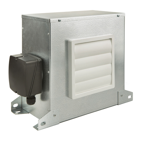
S&P MD6-ES24VK Installation and operating instructions

Installation, Operation, and Maintenance Manual
READ AND SAVE THESE INSTRUCTIONS
The purpose of this manual is to aid in the proper installation and operation of fans
manufactured by S&P USA. These instructions are intended to supplement good
general practices and are not intended to cover detailed instruction procedures,
because of the wide variety and types of fans manufactured by S&P USA.
6393 Powers Ave
Jacksonville, FL 32217
P: 800.961.7370
F: 800.961.7379
MD6-ES24VK-IOM_v.1 / 06-2018
MD6-ES24VK
READ AND SAVE THESE INSTRUCTIONS
The purpose of this manual is to aid in the proper installation and operation of fans
manufactured by S&P. These instructions are intended to supplement good general
practices and are not intended to cover detailed instruction procedures, because of
the wide variety and types of fans manufactured by S&P.


1
Installation Instructions
MD6-ES24VK
1. WARNINGS
READ AND SAVE THESE INSTRUCTIONS. FAILURE TO COMPLY
WITH INSTRUCTIONS COULD RESULT IN PERSONAL INJURY
AND/OR PROPERTY DAMAGE!
CAUTION:
(1) For General Ventilating Use Only. Do Not Use To Exhaust Hazardous Or Explosive Materials
And Vapors.
(2) The MD6-ES24VK is suitable for operation within indoor environments only.
WARNING: TO REDUCE THE RISK OF FIRE, ELECTRIC SHOCK OR INJURY, OBSERVE THE
FOLLOWING:
1. Use this unit only in the manner intended by the manufacturer. If you have questions, contact
the manufacturer.
2. Before servicing or cleaning unit, switch power o at service panel and lock the service
disconnecting means to prevent power from being switched on accidentally. When the service
disconnecting means cannot be locked, securely fasten a prominent warning device, such as
a tag, to the service panel.
3. Installation work and electrical wiring must be done by qualied person(s) in accordance with all
applicable codes and standards, including re-rated construction.
4. Sucient air is needed for proper combustion and exhausting of gases through the ue
(chimney) of fuel burning equipment to prevent back drafting. Follow the heating equipment
manufacturer’s guideline and safety standards such as those published by the National Fire
Protection Association (NFPA), and the American Society for Heating, Refrigeration and Air
Conditioning Engineers (ASHRAE), and the local code authorities.
5. When cutting or drilling into wall or ceiling, do not damage electrical wiring and other hidden
utilities.
6. Ducted fans must always be vented to the outdoors.
2. PRE-INSTALLATION INSPECTION
The MD6-ES24VK has been manufactured in accordance with rigorous standards of production. All the
components have been checked and tested at the end of the manufacturing process. We recommend
that you check the following after receiving this product:
1. The correct size has been received.
2. The correct model has been received.
3. The details on the rating label correspond to the electrical supply: voltage, frequency etc.
Remove the unit from packaging and inspect for shipping damage within 15 days of receipt. If the
product is found to be damaged, immediately contact your local authorized supplier. DO NOT OPERATE
THE UNIT IF DAMAGED. These instructions should be considered as a supplement to EPA standard
practices, as well as all state and local building code regulations.
Before installing the product check the following points:
1. The damper blade opens and closes freely.
2. There are no obstructions to the airow.
3. ENVIRONMENT
The MD6-ES24VK IS suitable for operation within indoor environments only. The MD6-ES24VK is
suitable for the supply of both conditioned and un-conditioned airstreams within the temperature ranges
(inclusive of duct airstream’s temperature) of -40°C up to +60°C.

2
4. MOUNTING
Choose a mounting location which allows convenient wiring and maintenance accessibility.
The MD6-ES24VK can be mounted in any orientation, horizontal or vertical, and is suitable
for supply/fresh air applications. The 6” MD6 motorized damper will be installed between
the fresh air wall cap/roof cap/sot vent (with insect screen) and the HVAC unit return
duct. The ES24V fresh air control can be mounted:
• On the 6” insulated ductwork between the wall cap and the MD6 motorized damper, or
(Note, the 24V power wires (R & C) will need to be extended from the HVAC unit power
supply or a separate 120V-24V transformer)
• On the HVAC unit (Note, the temperature (26AWG cable) and humidity (6P6C phone cable)
sensor wires will need to be extended.)

3
Make sure the temperature and humidity sensors are installed into the 6” insulated fresh
air duct between the wall cap and MD6 motorized damper if necessary.
5. DUCTING
All ducting and fresh air intake construction/location must comply with local and national building
codes. Do not locate fresh air intakes near contaminant sources (ex: dryer exhaust vent, garbage,
etc). Connect the ductwork to the wall cap and HVAC return duct with screws, cable ties, worm clamps,
and rated tape as necessary. Ensure that the ductwork is properly connected to a properly sized, low
restriction fresh air intake with weather hood and insect screen.
S&P recommends round 6” insulated rigid ductwork for best air and sound performance. Round 6”
exible ductwork is acceptable, but ensure that it is pulled tight to reduce losses. Keep the length of
duct and number of elbows to a minimum for best air and sound performance. Insulated ductwork
will minimize building heat loss/gain and reduce the potential for condensation.
The ducting from the HVAC unit fan to the outside of the building has a strong eect on the air ow, noise
and energy use of the fan. Use the shortest, straightest duct routing possible for best performance, and
avoid installing smaller ducts than recommended. Insulation around the ducts can reduce energy loss
and inhibit mold growth.
Ductwork connections and penetrations should be sealed with duct tape, duct fast-clamps, or caulk
(available through your local distributor) to create an air-tight path from the building exterior to the
ventilated space.
6. WIRING
CAUTION: Ensure that power is turned o and locked out before making any wiring connections.
The MD6-ES24VK operates from a standard 24V 60Hz AC electrical supply. There are multiple
wiring scenarios available depending on the installer preferences. The diagrams below show 3
common scenarios where the ES24V is connected either directly to the HVAC unit transformer or an
auxiliary transformer and the MD6 is connected either directly to the ES24V damper terminals or to
the ES24V damper terminals through a SPST, N.O. 24V relay and transformer. This will depend on
the VA available from the HVAC unit transformer. S&P recommends 20VA be available to operate
the MD6 motorized damper. If 20VA is not available from the HVAC unit transformer, then an
auxiliary transformer to power the ES24V and MD6 is recommended (transformers and relays provided
by others).
All wiring must be carried out by a qualied electrician in accordance with National Electrical Code and
all applicable state and local buildings codes. Electrical connections should be made in accordance
with the following Figures: 1-3

4
FIGURE 3
ES24V - (20VA NOT AVAILABLE FOR
DIRECT CONNECTION OF MOTORIZED
DAMPER)
SENSOR
C
TSTS
R
G
SENSOR
R
C
GG
C
R
TRANSFORMER
COMMON
FIGURE 1
ES24V - (20VA REQUIRED TO OPERATE MD6 MOTORIZED DAMPER.
CLASS II POWER SUPPLY CAN COME FROM HVAC TRANSFORMER,
IF ADEQUATE, OR AUXILIARY TRANSFORMER IF NECESSARY)
SENSOR
SENSOR
C
TSTS
R
G
R
C
GG
C
R
FIGURE 2
ES24V - (20VA NOT AVAILABLE FOR DIRECT CONNECTION
OF MOTORIZED DAMPER)
COMMON
TRANSFORMER
R
C
G
G
C
R
SENSOR
G
R
TS TS
C
SENSOR
Refer to the ES24V – Envirosense Ventilation Control IOM on pages 8-9 for ES24V wiring connections
and operation.

5
7. AIRFLOW SETTING
CAUTION: Refer to local and national Ventilation and Indoor Air Quality standards to ensure
the proper airow rate.
Ensure the HVAC unit air lter is clean and installed. Turn the ES24V to the “ON” position
and wait approximately 10 seconds for the HVAC unit fan to turn on and the MD6 motorized damper
to open. (Note, ensure that the Motorized Damper is enabled on the ES24V, refer to ES24V IOM on
page 8-9). Using a manometer, measure and record the airow through the fresh air duct (refer to
the manometer instructions). Once complete, turn the ES24V to the “OFF” position and calculate the
required continuous CFM based on the ventilation code.
ASHRAE 62.2-2010
Required Continuous CFM = ((0.01 * Floor Area in ft²) + 7.5(# of bedrooms + 1))
Example:
2,000 square foot dwelling
3 bedrooms
= 50 CFM continuous
ASHRAE 62.2-2013 & 2016
Required Continuous CFM = ((0.03 * Floor Area in ft²) + 7.5(# of bedrooms + 1))
Example:
2,000 square foot dwelling
3 bedrooms
= 90 CFM continuous
Now that the required continuous CFM is known, calculate the required run time / hour.
Run Time / Hour = 60 * (Required Continuous CFM / Actual Measured CFM)
Example (based on ASHRAE 62.2-2010 example above):
50 Required Continuous CFM
150 Actual Measured CFM
= 20 minutes / hour
Set the ES24V to the correct Run Time / Hour and High / Low Temperature & Humidity limits per the
ES24V IOM on pages 8-9.

6
Note, if the Actual Measured CFM is not enough, the installer may need to increase the duct size or add
a booster fan if necessary. Ensure there is no blockage in the ductwork rst.
9. MAINTENANCE
CAUTION: BEFORE CARRYING OUT ANY MAINTENANCE OR SERVICING, ENSURE THE UNIT IS
DISCONNECTED FROM THE MAIN ELECTRICAL SUPPLY.
S&P recommends inspection of the MD6 and ES24V at least once every twelve (12) months. To
inspect the unit disconnect from electrical supply. Remove the MD6 motorized damper from the fresh
air ductwork and inspect the damper blade for damage and proper function. If any debris is evident on
the damper blade clean with a damp (not wet) cloth. DO NOT USE any detergents or abrasive materials
for cleaning. Reinstall MD6 motorized damper to the fresh air ductwork and reseal joints.
Airow / Air Velocity Reference Table
Airow
(CFM)
Duct Size (in)
6 7 8
Air Velocity (FPM)
30 153 112 86
40 204 150 115
50 255 187 143
60 306 225 172
70 357 262 201
80 407 299 229
90 458 337 258
100 509 374 286
110 560 412 315
120 611 449 344
130 662 486 372
140 713 524 401
150 764 561 430
160 815 599 458
170 866 636 487
180 917 674 516
190 968 711 544
200 1019 748 573

7
11. WARRANTY
S&P USA - S&P Canada warrant that the MD6-ES24VK will be free from defective
materials and workmanship for the period of (5) years from the date of original purchase. In
the event that we nd any part is defective the product will be repaired or, in the Company’s
discretion, replaced without charge provided that the product has been installed in
accordance with the enclosed instructions and all applicable EPA Standards and state and
local building codes.
IF CLAIMING UNDER WARRANTY: Please return the complete product, freight paid, to your local
authorized distributor. All returns must be accompanied by a valid Bill Of Sale. All returns must be
clearly marked “Warranty Claim,” with an accompanying description stating the nature of the fault.
THE FOLLOWING WARRANTIES DO NO APPLY: Damages from shipping, either concealed or
visible. Claim must be led with the carrier. Damages resulting from improper wiring or installation
Damages caused by acts of nature, or resulting from improper consumer procedures such as: Improper
Maintenance; Misuse; Negligence; Alteration; Abuse; Abnormal Use; or Accident or Incorrect Electrical
Voltage and Current. Removal or alteration to the S&P USA - S&P Canada data plate label.
WARRANTY VALIDATION: The end user must keep a copy of the Bill of Sale to verify purchase date.
THE ABOVE (5) YEAR WARRANTY IS EXPRESSLY IN LIEU OF ALL OTHER WARRANTIES,
EXPRESSED, WRITTEN OR IMPLIED, INCLUDING THE WARRANTIES OF MERCHANTABILITY
AND FITNESS FOR USE. IN NO EVENT SHALL Soler & Palau USA - Soler & Palau CANADA
BE LIABLE FOR ANY SPECIAL, CONSEQUENTIAL, OR INCIDENTAL DAMAGES, INCLUDING
LOSS OF PROPERTY, REVENUES, LOST PROFITS, COSTS OF REMOVAL, INSTALLATION OR
REINSTALLATION.

8
The ES24V controls a ventilator to meet fresh air supply requirements
while limiting operation during periods of extreme temperature and/or
humidity.
INSTALLATION & OPERATION MANUAL
CAUTION:
1. READ AND SAVE THESE INSTRUCTIONS.
2. Before installation or maintenance, disconnect the power supply.
3. This control is for 24 VAC applications only.
4. All wiring must be done by qualified person(s) in accordance with
all applicable codes & standards.
WIRING
Use Copper Conductors Only
Terminal Type
Description
R
24Vac
Input: 24Vac input (50/60 Hz)
C
24Vac
Input: 24Vac common
G
24Vac
Input:
Furnace
Blower
(Optional)
B
24Vac
Output: Furnace Blower (2A max)
(Optional)
F+
24Vac
Output:
Fresh Air
Fan output + (2A max)
F
-
24Vac
Output:
Fresh Air
Fan output
-
(2A ma
x)
D+
24Vac
Output: Motorized Damper + (2A max)
(Optional)
D
-
24Vac
Output: Motorized Damper
-
(2A max)
(Optional)
H+
24Vac
Output: Duct Heater output + (2A max)
(Optional)
H
-
24Vac
Output: Duct Heater output
-
(2A max)
(Optional)
MOUNTING
Front Cover Removal
Insert a flathead screwdriver into the slot
on the right side of the controller and
apply gentle pressure inward and up so
that the front cover disengages from the
back cover. Pull the front cover up and to
the left.
Back Cover Mounting
Locate the control on the mounting surface being sure to allow clearance
for the necessary wiring connections. Mark the mounting hole locations and
remove the back cover from the work space. Make the stripped/labelled
wiring connections now. CAUTION: Be sure that no exposed portions of
wires are touching.
If installing onto wood, mount the back cover with the provided screws. If
installing onto drywall, drill pilot holes using a 7/32” drill bit (not provided)
and tap the provided drywall anchors into place. Mount with provided
screws. NOTE: Velcro can be used to mount the control instead of screws
if necessary.
Verify that wiring connections are correct and secure.
Align the front cover with the
back cover starting on the left
side. Push the front cover
towards the back cover in a
“hinging” motion from the left to
the right. CAUTION: Make sure
the front cover is aligned properly
with the back cover to avoid
damaging the control. Press
down until the front cover snaps
securely into place.
Sensor Mounting
The ES24V comes with a temperature sensor (26AWG, 2 wire) and
humidity sensor (6P6C, telephone wire), both 10” long. Install the sensors
at a location so that they will be exposed to the fresh air intake (ex: the
fresh air ductwork). Drill 2, 3/4" diameter holes, spaced appropriately and
install the sensors with the provided hardware. NOTE: the sensor wires can
be extended up to 300 feet without deviation. Use appropriate duct tape to
seal joints/openings as necessary.
DIMENSIONS (in)
SCREEN DIAGRAM
OPERATING MODES
OFF Mode: All outputs are off.
ON Mode: The Fresh Air Fan, Motorized Damper (if enabled), and
Furnace Blower (if enabled) are on continuously. The Duct Heater
will follow the user settings (see FUNCTION SETTINGS below).
Eco Mode: Eco Mode limits the Fresh Air Fan operation during
periods of extreme temperature and/or humidity. The Fresh Air
Fan, Motorized Damper (when enabled), Furnace Blower (when
enabled), and Duct Heater (when enabled) will follow the user
settings when the outside air temperature/humidity is within the
user set limits (see FUNCTION SETTINGS below).
The Fresh Air Fan will run for the user set amount of time/hour
while the temperature/humidity limits are within range. The
temperature/humidity sensors evaluate the fresh air conditions
every 10 seconds. While the fresh air temperature/humidity is
within the user set limits, the Fresh Air Fan/accessories will run
per the user settings. When the fresh air temperature/humidity
exceeds the user set limits, the Fresh Air Fan/accessories will turn
off and engage a timer. The timer will run the fan for 5 minutes
every 15 minutes in order to meet code requirements. NOTE: the
Furnace Blower (if enabled) will not run during this check
procedure to prevent cycling. The fan will continue this check
procedure until the temperature/humidity limits are within the user
set limits.
If Enabled (in SETUP):
The Furnace Blower will be on: any time there is a call from “G”
Input or any time the Fresh Air Fan is on (excluding the check
procedure above).
The Motorized Damper will be on anytime the Fresh Air Fan is on.
The Duct Heater will be on any time the Fresh Air Fan is on and
the set point > room temperature +2°F.
(Motorized Damper, Furnace Blower, and Duct Heater are
required to be enabled in SETUP)
BUTTONS
Keys Description
Mode Select the operating mode
Set Confirm settings
▲ Increase settings
▼ Decrease settings
ES24V
Envirosense Ventilation Controller
Operating Modes: OFF, ON, or Eco
Motorized Damper indicator
Relative Humidity %
Temperature (F or C)
Thermostat integration indicator
Fresh Air Fan indicator
Duct Heater indicator

9
SETUP
Press and hold [MODE] for 3 seconds to enter setup mode.
OR
01 Optional Duct Heater (Default: heater disabled)
Press [▲]/[▼] to enable or disable duct heater.
Press [SET] to confirm settings.
OR
02 Temperature Unit (Default: degrees F)
Press [▲]/[▼] to select degrees C or degrees F.
Press [SET] to confirm settings.
OR OR
03 Humidity/Temperature (Default: temperature and humidity)
Press [▲]/[▼] to evaluate temperature only, humidity only or both
temperature and humidity.
Press [SET] to confirm settings.
OR
04 Optional Motorized Damper (Default: motorized damper disabled)
Press [▲]/[▼] to enable or disable motorized damper.
Press [SET] to confirm settings.
OR
05 Optional Thermostat Integration (Default: standalone system)
Press [▲]/[▼] to enable or disable thermostat integration.
Press [SET] to confirm settings.
06 Fan Run Time per Hour (Default: 15 minutes)
Press [▲]/[▼] to adjust 5-60 Minutes/Hour (Increments of 5).
Press [SET] to confirm settings and return to normal mode.
All setting screens will return to the normal mode screen automatically after
20 seconds.
FUNCTION SETTINGS
Press <Set> key to set the temperature/humidity limits and duct heater set
point.
FACTORY RESET
Press and hold [▲]&[▼] buttons in OFF mode for ~5 seconds to
reset the control to factory settings.
will be displayed on the
screen when complete.
FEATURES
Voltage supply: 24VAC +/- 15% 50/60Hz
System mode: Off / On / Eco
Temperature unit mode: F or C
Temperature measurement range: 15F - 130F (-10C to
55C)
High Limit Temperature settings range: 65 -105°F (18C to
40C)
Low Limit Temperature settings range: 20 - 60°F ( -6C to
16C)
Heater Temperature settings range: 32°F - 62°F (0°C -
16°C)
Temperature resolution: 1 °F or 0.5C
Temperature Accuracy: +/-1 °F or 0.5C
Humidity measurement range: 10-95%
High Limit Humidity settings range: 55-90%
Low Limit Humidity settings range: 10-50%
Humidity resolution: 1 %
Humidity Accuracy: +/- 5 %
10 inch RJ11 (6 wires) phone cable for humidity sensor
10 inch 26AWG (2 wires) cable for temperature sensor
Max Sensor Wire Length: 300 feet (100 m)
Motorized Damper relay output (Maximum 2A)
Fan relay output (Maximum 2A)
Duct Heater relay output (Maximum 2A)
Furnace Blower Output (Maximum 2A)
Non-volatile memory to store settings, configuration
parameters
Operating temperature: 15F to 130F (-10 C to 55C)
Storage temperature: -20F to 158F (-29 C to 70C)
Temperature limit of mounting surface: 130F (55C)
Terminals: 2.5mm
2
cable
Pollution Degree: 2
Degree of protection: IP20
Electronic control: Type 2.B
Class II Control
cULus listed: UL60730-1
Housing Material: Lexan 943(f1), 1.6mm thick, V-0 (UL94
Rating)
Time Setting Range: 5-60 Minutes
Power: 1.5W (Max)
180129
Press [▲]/[▼] to change the high limit
temperature setting.
Press [SET] to confirm settings.
Press [▲]/[▼] to change the high limit
humidity setting.
Press [SET] to confirm settings.
Press [▲]/[▼] to change the low limit
temperature setting.
Press [SET] to confirm settings.
Press [▲]/[▼] to change the duct heater
activation temperature setting.
Press [SET] to confirm settings and return to
normal mode.
Press [▲]/[▼] to change the low limit
humidity setting.
Press [SET] to confirm settings.

Table of contents
Other S&P Fan manuals

S&P
S&P PBB 2-315 User manual

S&P
S&P CTB ECOWATT User manual

S&P
S&P ARTIC TOWER N User manual

S&P
S&P IRAB-N User manual

S&P
S&P SILENT CHZ DESIGN User manual

S&P
S&P UVF ECOWATT Series User manual

S&P
S&P ILB-ILT ILT/4-285 User manual

S&P
S&P CE ATEX Installation guide

S&P
S&P AIRPUR-N User manual

S&P
S&P ARTIC-255N GR User manual
Popular Fan manuals by other brands

Viessmann
Viessmann VITOVENT 300 Service instructions for contractors

Westinghouse
Westinghouse WSFNCP001BK instruction manual

Exhausto
Exhausto VEX330H OD manual

HIRED-HAND
HIRED-HAND Econo-Flow quick start guide

Clatronic
Clatronic VL 3603 S instruction manual

Scarlett
Scarlett Comfort SC-SF111B16 instruction manual