Trane FWDP Series Owner's manual

TRANE
R
Installation
Operation
Maintenance
Commercial
Chilled Water
Blower Coil Unit, FWDP
Models
FWDP 008 FWDP 024
FWDP 014 FWDP 028
FWDP 018 FWDP 032
FWDP-SVX01A-E4 (June 08)

TRANE
®

TRANE
®
i
General Information
Foreword
These instructions do not attempt to
cover all variations in systems, nor to
provide for every possible contigency
to be met in connection with
installation. Should further information
be desired or should particular
problems arise which are not
sufficiently covered for the purchaser's
purpose, the matter should be referred
to the manufacturer.
Warranty
Warranty is based on the general terms
and conditions of Trane Company. The
warranty is void if the equipments is
repaired or modified without the written
approval of the manufacturer, if the
operating limits are exceeded or if the
control system or the electrical wiring
is modified. Damage due to misuse,
lack of maintenance or failure to comply
with the manufacturer's instructions or
recommendations is not covered by the
warranty obligation.
Reception
On arrival, inspect the unit before
signing the delivery note. Specify any
damage on the delivery note, and send
a registered letter of protest to the last
carrier of the goods within 72hours of
delivery. Notify the local Trane Sales
Office at the same time. The unit
should be totally inspected within 15
days of delivery. If any concealed
damage is discovered, stop unpacking
the shipment. Take photos of the
damaged material if possible. Notify
the Carrier immediately by phone and
registered mail. Notify the local Trane
Sales Office. Concealed damage must
be reported within 15 days of delivery.
Check the unit nameplate to confirm
that the proper unit was shipped.
Available power supply must be
compatible with electrical
characteristics specified on
component nameplates.
Installation
General Information
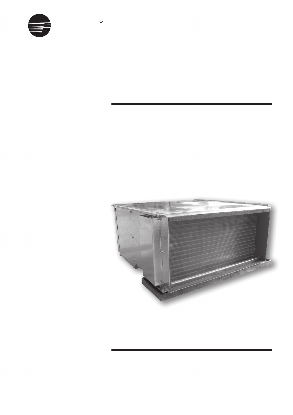
This manual covers the installation,
operation and maintenance of the
Trane FWDD Chilled Water Blower Coil
units. These new air handler models
are completely redesigned to
incorporate a single slab coil
assembly, improved application
flexibilty, servicing and maintenance
accessibility and an improved
accessory line.
Note:
"Warnings" and "Cautions"
appear at appropriate places in this
manual. Your personal safety and the
proper operation of this machine
require that you follow them carefully.
The manufacturer assumes no liability
for instllations or servicing performed
by unqualified personnel.
Handling
The unit will be supplied with a
shippling base and protective
packaging over the unit casing. The
packaging should be kept on the unit
during handling or storage on site.
If it is necessary to remove the
packaging for inspection prior to
completion of on site handling, retain
packaging parts and reapply them by
tapping in position to prevent damage
to the casing. The unit as supplied
has a shipping base which is suitable
for handling by a fork lift truck. If it is
necessary to sling the unit, use
spreader bars under the shipping
base. Ensure that ropes do not cause
abrasion to the surface of the unit.

TRANE
®
ii
Content
General Information
Model Nomenclature
General Data
Dimensional Data
Unit Installation
Wiring Diagrams
Unit Installation
i
1
2
3
4-6
7
8

TRANE
®
1
FWDP
MODEL NOMENCLATURE

TRANE
®
2
General Data
FWDP, 008, 014, 018, 024, 028, 032
GENERAL UNIT CONSTRUCTION
Cooling coil
Tube size, OD
Face area
Water in/out size
Drain pipe size
Fan type
Quantity
Drive type
Number of speed
Number of motor
Power input
Full Load Amps,
Hi/Med/Lo
Filter
Quantity
Size (nominal)
Net weight
unit
mm
m2
mm
mm
pc
pc
KW
Amps
pc
kg
FWDP008
9.5
0.26
1
1 speed
1
0.165
1.3
1
16"x25"
54
FWDP014
9.5
0.26
1
1
0.55
5.6/5.3/4.5
1
16"x25"
58
FWDP018
9.5
0.33
1
1
0.55
5.6/5.3/4.5
1+1
15"x20"/15"x15"
68
FWDP024
9.5
0.46
2
1
0.75
5.8/5.5/4.4
1 + 1
16"x20"/16"x25"
82
FWDP028
9.5
0.62
2
1
1.1
9/8.5/7.5
3
16"x20"
114
FWDP032
9.5
0.67
2
1
1.1
9/8.5/7.5
2 + 1
16"x20"/16"x25"
120
FC Centrifugal
Direct drive
3 speeds
1” (25mm) BSPT Male THD
3/4" (19mm) BSPT Male THD
25mm

TRANE
®
3
Dimensional Data
FWDP 008/014/018/024/028/032
Table 1: - Fan Coil Dimensions
Note: - Dimensions are in mm.
NOTES: -
KDD FAN FOR FWDP 008/014/018
KD2 FAN FOR FWDP 024/028/032
MODEL
008/014
018
024
028
032
A
635
813
1148
1524
1651
B
669.5
847.5
1182.5
1558.5
1685.5
C
703.5
881.5
1216.5
1592.5
1719.5
MODEL
008/014
018
024
028
032
3 ROWS
161
D
4 ROWS
183
6 ROWS
227

TRANE
®
4
Unit Installation
The general location of the air handler
is normally selected by the architect,
contractor, and/or buyer. For proper
installation, the following items must
be considered.
1.Available power supply must agree
with electrical data on component
nameplate.
2.Air handlers shipped wired for 220 -
240 Volt applications.
3.If external accessories are installed
on the unit, additional clearances
must be provided.
4.All duct work should be properly
insulated to prevent condensation
and heat loss.
Note: It is recommended that the
outline drawings (page6) be studied
and dimensions properly noted and
checked against selected installation
site.
Important:
If adding external
accessories to the unit, additional
clearances must be considered for the
over all space needed.
Lifting Recommendation
Before preparing the unit for lifting, the
center of gravity should be determined
for lifting safety. Because of the
placement of internal componets, the
unit weight may be unevenly
distributed.
WARNING: OPEN AND
LOCK UNIT DISCONNECT TO
PREVENT INJURY OR DEATH
FROM ELECTRIC SHOCK OR
CONTACT WITH MOVING
PARTS BEFORE ATTEMPTING
ANY INSTALLATION OR
MAINTENANCE.
The unit can be moved using a forklift
of suitable capacity. For lifting the unit
into an elevated mounting pasition, run
lifting straps or slings under the unit
and attach securely to the lifting device.
Use spreader bars to protect the unit
casing from damage. Test lift the unit
to determine proper balance and
stability.
Caution: Use spreader bars to prevent
straps from damaging the unit. Install
the bars between lifting straps, both
underneath the unit and above the unit.
This will prevent the straps from
crushing the unit cabinet or damaging
the unit finish.
Installation Considerations
For proper installation and operation,
check each of the following before
mounting the units.
(a)Space Requirement And
Clearances.
Allow adequate space for the unit and
free air service clearances. See Figure
in page 3 general unit dimensions.
For servicing and routine maintenance,
provide access to the unit through
removable panels in the ceiling..
WARNING: ON SITE
LIFTING EQUIPMENT MUST
BE CAPABLE OF LIFTING THE
WEIGHT OF THE UNIT WITH
AN ADEQUATE SAFETY
FACTOR. THE USE OF UNDER
CAPACITY LIFTING DEVICES
MAY RESULT IN PERSONAL
INJURY OR DEATH AND
CAUSE DAMAGE TO THE
UNIT.
! ! Figure 1
(b) Location, Mounting And Positioning
Before installing any unit make sure
proper preparation has been made
at each unit location for piping and
electrical connections.

TRANE
®
5
The unit should be installed for
horizontal application only. Suspend the
unit using the factory-provided threaded
mounting holes on top of the unit. This
is usually accomplished through the
use of spring or rubber isolators, which
are to be furnished by the installer.
All units must be mounted level to
assure proper drainage and
operation.
Check that the supporting structure
is strong enought to support unit
weights.
Align the mounting holes with structural
support and secure suspension rods
to the structure, then to the air handler
cabinet. If the mounting holes locations
do not permit proper alignment with
existing structure. It may be necessary
to field fabricate cross members on
existing structural beams.
(c) Coil Piping Connections.
Coils are fitted with 1-1/4" (32mm)
BSPT MALE threaded connections. To
complete piping connections, attach the
water piping with 1-1/4 inch connection
to the coil. The water inlet is on the
bottom and water outlet on the top of
the coil. Coil connection size and coil
connection locations are given in page
3.
(d) Condensate Drain
Connections.
These air handlers come standard with
a drain pan. Drain connections are
provided on one side of the air
handlers.
For a typical drain trap assembly, see
Figure 2.
Figure 2
Drain Pan Trapping for unit under
Prositive Pressure
Prositive Pressure Module
The positive pressure unit requires a
different design than the negative
pressure trap. Refer to Figure and the
formula provided to determine the
minimum trap depth.
Unit Installation
K = min. 1/2
H = 1/2 plus maximum total static
pressure
008 / 014 / 018
H = 1”
024 / 028 / 032
H = 1.5”

TRANE
®
6
Unit Installation
(e) Auxiliary Drain Pan
A field fabricated auxiliary drain pan
should be installed under the unit
especially if the unit is installed above
ceilings or in other locations where
condensate overflow may cause
damage. This drain pan will eliminate
any excess condensation that may be
due to extreme humidity or an
obstructed drain in the primary drain
pan. Drain lines from this pan must be
installed, but should not be connected
to the primary drain line from the unit.
Isolate the auxiliary drain pan from both
the air handler and the structure.
(f) Filters
Air handlers are shipped with 1 filters
installed in the unit. For filter
dimensions, refer to page 5. (General
data).
To replace filters remove side access
panel (either end and slide old filters
out and replace with new ones.
Figure 3
(g) Duct Connections
The supply and return ducts should be
connected to the unit with flame
retardant duct connectors to reduce
vibration transmission. The return duct
should be sized to the same
dimensions as the return inlet of the
unit. Refer to Figure in page 3 for the
dimension.
(h) Electrical Connections
1. All electrical lines, sizing, protection
and ground ing must be in
accordance with the National Electric
Code and local codes.
2. If conduit is used, isolate whenever
vibration transmission may cause a
noice problem within the building
structure.
3. Ensure all connections are tight and
no wires exposed.
4. All accessories must be installed
and wired according to the
instructions packaged with that
accessory.
Installation Checklist
Complete this checklist once the unit is
installed to verify that all recommended
procedures have been accomplished
before the system is started.
Operational checks cannot be
performed until the system in
terconnection is complete.
WARNING: WHEN
INSTALLING OR SERVICING
THIS EQUIPMENT, ALWAYS
EXERCISE BASIC SAFETY
PRECAUTIONS TO AVOID THE
POSSIBILITY OF ELECTRIC
SHOCK THAT COULD RESULT
SEVERE PERSONAL INJURY
OR DEATH.
!
1.Verify that the unit electrical power is
disconnected.
2.Inspect all field wiring connections.
All connections should be clean and
tight.
3.Inspect unit suspension
arrangement(s). Ground must
comply with all applicable codes.
4.Inspect unit suspension
arrangement (if used). Unit position
must be secure. Remove any tools
or debris found in or near the unit.
5.Inspect duct outlets. Outlets must be
open and unrestricted.
6.Inspect unit drain lines. Pipe
connections must be tight and drain
line unrestricted.
7.Inpect fan assembly to insure all
moving parts move freely.
8.If unit is horizontally mounted, make
sure secondary drain pan has been
installed.
9.Inspect unit for proper filters, securely
installed. All cabinet panels must be
secured.
10.Instruct owner/operator on proper
system operating and maintenance
procedure.

TRANE
®
7
Wiring Diagram

TRANE
®
8
Unit Installation
Maintenance Contract
It is strongly recommended that you
sign a maintenance contract with your
local Service Agency. This contract
provides regular maintenance of your
installation by a specialist in our
equipment. Regular maintenance
ensures that any malfunction is
detected and corrected in good time and
minimizes the possibility that serious
damage will occur. Finally, regular
maintenance ensures the maximum
operation life of your equipment. We
would remind you that failure to respect
these installation and maintenance
instructions may result in immendiate
cancellation of the warranty.
Training
The equipment described in this
manual is the result of many years of
research and continuous
developement. To assist you in
obtaining the best use of it, and
maintaining it in perfect operating
condition over a long period of time, the
constructor have at your disposal a
refrigeration and air conditioning
service school. The principal aim of
this is to give operators and
maintenance technicians a better
knowledge of the equipment they are
using, or that is under their charge.
Emphasis is particualrly given to the
importance of periodic checks on the
unit operating parameters as well as
on preventive maintenance, which
reduces the cost of owning the unit by
avoiding serious and costly breakdown.

The constructors policy is one of continuous product
improvement, and he reserves the right to alter any
details of the products at any time without notice.
This publiction is a general guide to install, use and
properly maintain our products. The information given
may be different from the specification for a particular
country or for a specific order. In this event, please refer
to your nearest TRANE office.
For additional information, contact:
FWDP-SVX01A-E4 (June 2008)
FWDP-SVX01A-E4 (July 2006)
Malaysia
Literature Order Number
File Number
Supersedes
Stocking Location
Trane has a policy of continuous product and product data improvement and reserves the right to
change design and specifications without notice. Only qualified technicians should perform the installation
and servicing of equipment referred to in this publication.
Trane
www.trane.com
For more information, contact your local district
office
TRANE
®
This manual suits for next models
6
Table of contents
Other Trane Blower manuals