Trane Ice Bank User manual

Ice Bank®Energy Storage
Operation and Maintenance Manual
August 2020 IB-SVX147D-EN
SAFETY WARNING
Only qualified personnel should install and service the equipment. The installation, starting up, and servicing of
heating, ventilating, and air-conditioning equipment can be hazardous and requires specific knowledge and training.
Improperly installed, adjusted or altered equipment by an unqualified person could result in death or serious injury.
When working on the equipment, observe all precautions in the literature and on the tags, stickers, and labels that are
attached to the equipment.

© 2020 Trane IB-SVX147D-EN
Introduction
Read this manual thoroughly before operating or servicing
this unit.
Warnings, Cautions, and Notices
Safety advisories appear throughout this manual as
required. Your personal safety and the proper operation of
this machine depend upon the strict observance of these
precautions.
The three types of advisories are defined as follows:
WARNING Indicates a potentially hazardous
situation which, if not avoided, could
result in death or serious injury.
CAUTIONsIndicates a potentially hazardous
situation which, if not avoided, could
result in minor or moderate injury. It
could also be used to alert against
unsafe practices.
NOTICE Indicates a situation that could result in
equipment or property-damage only
accidents.
Important Environmental Concerns
Scientific research has shown that certain man-made
chemicals can affect the earth’s naturally occurring
stratospheric ozone layer when released to the
atmosphere. In particular, several of the identified
chemicals that may affect the ozone layer are refrigerants
that contain Chlorine, Fluorine and Carbon (CFCs) and
those containing Hydrogen, Chlorine, Fluorine and
Carbon (HCFCs). Not all refrigerants containing these
compounds have the same potential impact to the
environment. Trane advocates the responsible handling of
all refrigerants-including industry replacements for CFCs
and HCFCs such as saturated or unsaturated HFCs and
HCFCs.
Important Responsible Refrigerant
Practices
Trane believes that responsible refrigerant practices are
important to the environment, our customers, and the air
conditioning industry. All technicians who handle
refrigerants must be certified according to local rules. For
the USA, the Federal Clean Air Act (Section 608) sets forth
the requirements for handling, reclaiming, recovering and
recycling of certain refrigerants and the equipment that is
used in these service procedures. In addition, some states
or municipalities may have additional requirements that
must also be adhered to for responsible management of
refrigerants. Know the applicable laws and follow them.
WARNING
Proper Field Wiring and Grounding
Required!
Failure to follow code could result in death or serious
injury. All field wiring MUST be performed by qualified
personnel. Improperly installed and grounded field
wiring poses FIRE and ELECTROCUTION hazards. To
avoid these hazards, you MUST follow requirements for
field wiring installation and grounding as described in
NEC and your local/state electrical codes.
WARNING
Personal Protective Equipment (PPE)
Required!
Failure to wear proper PPE for the job being undertaken
could result in death or serious injury. Technicians, in
order to protect themselves from potential electrical,
mechanical, and chemical hazards, MUST follow
precautions in this manual and on the tags, stickers,
and labels, as well as the instructions below:
• Before installing/servicing this unit, technicians
MUST put on all PPE required for the work being
undertaken (Examples; cut resistant gloves/sleeves,
butyl gloves, safety glasses, hard hat/bump cap, fall
protection, electrical PPE and arc flash clothing).
ALWAYS refer to appropriate Safety Data Sheets
(SDS) and OSHA guidelines for proper PPE.
• When working with or around hazardous chemicals,
ALWAYSrefer tothe appropriateSDSandOSHA/GHS
(Global Harmonized System of Classification and
Labeling of Chemicals) guidelines for information on
allowable personal exposure levels, proper
respiratory protection and handling instructions.
• If there is a risk of energized electrical contact, arc, or
flash, technicians MUST put on all PPE in accordance
with OSHA, NFPA 70E, or other country-specific
requirements for arc flash protection, PRIOR to
servicing the unit. NEVER PERFORM ANY
SWITCHING, DISCONNECTING, OR VOLTAGE
TESTING WITHOUT PROPER ELECTRICAL PPE AND
ARC FLASH CLOTHING. ENSURE ELECTRICAL
METERS AND EQUIPMENT ARE PROPERLY RATED
FOR INTENDED VOLTAGE.

WARNING
Follow EHS Policies!
Failure to follow instructions below could result in
death or serious injury.
• All Trane personnel must follow the company’s
Environmental, Health and Safety (EHS) policies
when performing work such as hot work, electrical,
fall protection, lockout/tagout, refrigerant handling,
etc. Where local regulations are more stringent than
these policies, those regulations supersede these
policies.
• Non-Trane personnel should always follow local
regulations.
Introduction
IB-SVX147D-EN 3
Copyright
This document and the information in it are the property of
Trane, and may not be used or reproduced in whole or in
part without written permission. Trane reserves the right
to revise this publication at any time, and to make changes
to its content without obligation to notify any person of
such revision or change.
Trademarks
All trademarks referenced in this document are the
trademarks of their respective owners.
Revision History
Updated for Trane Technologies.

4IB-SVX147D-EN
Introduction
For thermal energy storage to efficiently and effectively
cool a building, it is important for the operators and
maintenance personnel to understand the overall con-
cept, not just the monthly routine. Therefore, we have
started this manual with a brief overview of the technol-
ogy and its application.
Air-conditioning can account for over 40% of average
summer peak-day loads.1In the afternoon, as more air
conditioning is needed to maintain comfortable tem-
peratures, the increased demand for electricity adds to
that already created by lighting, operating equipment,
computers and thousands of other uses. This requires the
utility to use additional, more costly generating sources to
handle its increased demand. Commercial users, whose
large air-conditioning loads contribute to these added
generating requirements are normally assessed an
additional charge based on their highest on-peak demand
for electricity.
Thermal energy storage will not significantly lower
demand charges during the air-conditioning season but
also can lower total energy usage as well. It uses a
standard package chiller to produce solid ice at night
during off-peak periods when the building’s electrical
needs are at a minimum and the utility’s generating
capacity is typically underutilized. The ice is built and
stored in modular Ice Bank®energy storage tanks to
provide cooling to help meet the building’s air-
conditioning load requirement the following day.
Figure 1. Counterflow heat exchanger tubes
Product Description and Normal
Operation
The Ice Bank tank is a modular, insulated polyethylene tank
containing a spiral-wound plastic tube heat exchanger
which is submerged in water. They are available in various
sizes. At night, a solution typically 75% water and 25%
ethylene glycol, circulates through a standard packaged
air-conditioning chiller and the tubing in the tank heat
exchanger, extracting heat until eventually almost all the
water in the tank is frozen solid. The ice is built uniformly
throughout the tank by the patented temperature-
averaging effect of closely spaced counterflow heat
exchanger tubes (see Figure 1). Water does not become
surrounded by ice during the freezing process and can
move freely as ice forms, pre- venting stress or damage to
the tank.
Flow diagrams for a Partial Storage system are shown in
Figure 2 and Figure 3. The temperatures shown are typical
however, many other ranges are used.
Figure 2. Charge cycle flow diagram
Figure 3. Discharge cycle flow diagram
1ACEEE 2008 Summer Study on Energy Efficiency in Buildings.
Charge Cycle
Chiller
Ice Bank
Ta n k Temperature
Modulating Valve
Automatic Diverting Valve
Coil
25˚F (-3.9˚C) 31˚F (-0.56˚C)
25˚F
(11.1˚C)
31˚F
(1.1˚C)
Coil
52˚F (11.1˚C) 60˚F (15.6˚C)
60˚F (15.6˚C)
55˚F
(12.8˚C)
44˚F (6.7˚C)
75˚F
(23.9˚C)
44˚F
(6.7˚C)
52˚F (11.1˚C)
52˚F
(11.1˚C)
34˚F
(1.1˚C)
Discharge Cycle
Chiller
Ice Bank
Ta n k Temperature
Modulating Valve
Automatic Diverting Valve

Introduction
IB-SVX147D-EN 5
In a standard installation, ice is made at night. The water-
glycol solution circulates through the chiller and the Ice
Bank®heat exchanger, bypassing the air handler coil. (See
Figure 2). The fluid temperature is about 25F (-3.9C) and
the water surrounding the heat exchanger freezes.
During the day, the glycol solution is cooled by the Ice
Bank®tank from approximately 52ºF to 34ºF (11ºC to 1ºC).
(See Figure 3). A temperature modulating valve is used to
maintain a blended supply temperature typically 44ºF
(6.7ºC), by permitting sufficient 52F (11.1C) fluid to
bypass the Ice bank®tank and mix with the 34F (1.1C)
fluid, to achieve the desired 44F (6.7C) temperature. The
44F (6.7C) fluid enters the coil, where it cools air
ordinarily from 75F to 55F (24C to 13C). The fluid leaves
the coil at 60F (15.6C), enters the chiller and is cooled to
52F (11.1C). In some systems, the ice will handle the
entire day time load (Full Storage) and in others, the ice
will help a smaller than full size chiller meet the load
(Partial Storage).
Maintenance
Since there are no moving parts in our standard thermal
storage tanks, the list of maintenance items is short. The
items we do list are important and should be done at
regular intervals as indicated. The inspection port cover
must always be replaced.
Water Level
The water level in the tank will rise and fall 2.5 to 7.8 inches
(63 to 195mm) (depending on Model No. of tank) during
the charge and discharge cycle. This change is due to
difference in the density of water and ice. Water expands
approximately 9% when changing to ice at 32ºF (0ºC);
therefore, during the freezing process, the level will rise.
(More about this in later sections). The water stays in the
tank (it is NOT pumped through the system) and the
amount of water/ice in the tank remains constant except
for possibly a slight amount of evaporation, which
normally occurs in outdoor, very hot, dry climates.
The water level should be just covering the top heat
exchanger tube, (which is 5/8 inch (16mm) diameter and
translucent) except for Model 1220, which is filled to the
bottom of the top HX tube. This measurement must be
done with no ice in the tank. The water level should be
checked every year except in hot, dry climates when every
three months is recommended.
Inventory Meter Calibration
During operation the only time to accurately check that the
the inventory meter probe level is correct is when the tank
is 100% charged. (See Ice Inventory Meter Manual IB-153
for more information.)
Coolant Concentration
The coolant should be checked regularly in accordance
with the manufacturer’s recommendations. For ethylene
glycol mixtures, after the initial start up periods, a sample
should be sent once a year to the manufacturer for
analysis. Checking the coolant’s freeze point is
recommended twice a year using a refractometer or
hydrometer, and not an automotive float-type device. The
maximum freezing point for our system is normally
12ºF (-11.1ºC) (25%EG/H2O); however, some jobs require
lower freeze points because of particular operating
conditions.
Storage Tank Water Treatment
Pour in the initial treatment of biocide into the tank water
upon filling. Generally, if tanks are kept at least partially
frozen year round, provide retreatment with biocide as
needed. However, if tanks are not kept frozen year round,
retreatment may be required more often and the tanks
should be checked for slime or odor seasonally. At the end
of the cooling season, you should fully charge the tanks
and leave them frozen until the start of your next air-
conditioning season. This will help to control biological
growth. CALMAC®recommends a 20% Tetrakis
hydroxymethyl phosphonium sulfate solution such as
Aquacar PS20. All tank models require 16 oz. of biocide
solution per tank.
The CAS number is 555-66-30-8
Minimum shut off temperature
In most systems, the termination of the charge cycle is
determined by the temperature of the coolant leaving the
storage tanks. Typically this temperature is in the range of
27-28F (-2.7 to -2.2C). However, it is imperative that the
actual temperature be calculated for each system using
CALMAC Performance Data (IB-102).
This temperature is calculated by adding Coolant
Temperature Rise to the minimum Charging Coolant
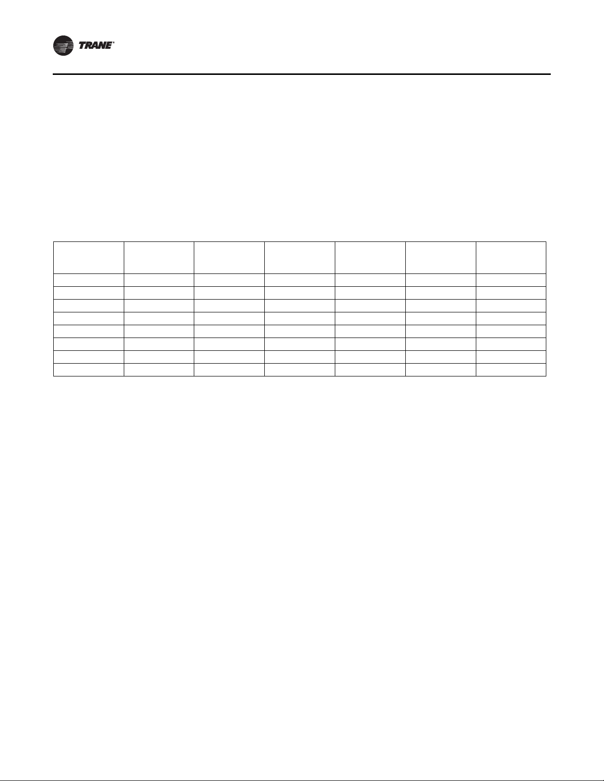
Temperature. This temperature should be entered in the
first line of the maintenance record, (See Table 1), and
checked once every six months.
Ice Caps
The shut-off temperature previously discussed, is very
important. Setting the temperature lower than what is
stated in the Performance Data can cause the water in the
expansion area above the heat exchanger to freeze. It is
important that this water does not freeze so that it is
available to fill the voids created by the melting ice during
discharge. Therefore, twice a year the tank should be
checked for excessive ice-build-up above the top heat
exchanger tube. Ice thicker than 1 inch is an early
indication that the shut-off temperature is set too low.

Introduction
6IB-SVX147D-EN
Tanks include a patented design which incorporates a
layer of insulation located just above the heat exchanger to
reduce the likelihood of Ice Caps. Inspection should still be
done twice a year and no ice should be seen above the
insulation layer.
Warranty Repairs
Authorization for in-warranty field repair or replacement
parts must be obtained in writing before any repairs are
attempted.
A purchase order must be entered through the local
CALMAC®representative for any possible warranty work
or replacement parts.
After CALMAC inspection of the returned part, and if it is
determined that the failure is due to our workmanship or
material defect, a credit will be issued against the
customer’s purchase order.
Table 1. Maintenance record
Date
Water Level
Above top of
tube w/no ice
Coolant
Freeze Temp.
Coolant
Analysis by
Mfr.
Water
Treatment
(Biocide)
Shut-off
Temperature
Ice Cap
Present
For example 1/4 inch (6mm) 12°F (-11.1°C) Yes Yes 28°F (-2.2 °C) No
Note: To find out more about Ice Bank®energy storage
visit calmac.com or trane.com/energy storage.


©2020 Trane
Trane has a policy of continuous product and product data improvement and reserves the right to change design and specifications without
notice. We are committed to using environmentally conscious print practices.
Trane - by Trane Technologies (NYSE: TT), a global climate innovator - creates comfortable, energy
efficient indoor environments for commercial and residential applications. For more information,
please visit trane.com or tranetechnologies.com.
IB-SVX147D-EN 07 Aug 2020
Supersedes IB-SVX147C-EN (Jun 2019)
Other manuals for Ice Bank
1
Table of contents
Other Trane Storage manuals
Popular Storage manuals by other brands

HP
HP AU183AA - 2TB Personal Media Drive Limited warranty

MXI Security
MXI Security stealth hd bio quick start guide

DANE-ELEC
DANE-ELEC SO EXTREME SSD MIGRATION KIT Getting started guide

Certance
Certance LTO 1 user guide

Stardom
Stardom DR5-SB3 user manual

Overland Storage
Overland Storage NEOs StorageLoader quick start guide

NETGEAR
NETGEAR SC101 - Storage Central NAS Server Installation overview

ADTX
ADTX ArrayMasStor K Series Installation manual and user's guide

HP
HP StorageWorks 1000 - Modular Smart Array specification

Quantum
Quantum PX502 introduction

Skope
Skope BB380r-2 Assembly, installation and operation instructions

LaCie
LaCie FastKey user manual