Transmille EA015 User manual

EA015
MULTI FUNCTION WORKSTATION ADAPTER
OPERATION MANUAL
Ü

Version 1.10
July 2008
All product names are trademarks of their respective companies
EA015
Multi Function Workstation
Operation Manual

EA015 MULTI FUNCTION WORKSTATION
OPERATION MANUAL
Transmille Ltd. Page 2
Guarantee and service
Transmille Ltd. guarantees this instrument to be free from defects under
normal use and service for a period of 1 years from purchase. This guarantee
applies only to the original purchaser and does not cover fuses, or any
instrument which, in Transmille’s opinion, has been modified, misused or
subjected to abnormal handling or operating conditions.
Transmille’s obligation under this guarantee is limited to replacement or
repair of an instrument which is returned to Transmille within the warranty
period. If Transmille determines that the fault has been caused by the
purchaser, Transmille will contact the purchaser before proceeding with any
repair.
To obtain repair under this guarantee the purchaser must send the instrument
in its original packaging (carriage prepaid) and a description of the fault to
Transmille at the address shown below. The instrument will be repaired at the
factory and returned to the purchaser, carriage prepaid.
Note :
TRANSMILLE ASSUMES NO RESPONSIBILITY FOR DAMAGE IN TRANSIT
THIS GUARANTEE IS THE PURCHASER’S SOLE AND EXCLUSIVE
GUARANTEE AND IS IN LEIU OF ANY OTHER GUARANTEE, EXPRESSED OR
IMPLIED. TRANSMILLE SHALL NOT BE LIABLE FOR ANY INCIDENTAL,
INDIRECT, SPECIAL OR CONSEQUENTIAL DAMAGES OR LOSS.
Transmille Ltd.
Unit 4, Select Business Centre
Lodge Road
Staplehurst
Kent
TN12 0QW
United Kingdom
Tel : +44 0 1580 890700
Fax : +44 0 1580 890711
Web : www.transmille.com

EA015 MULTI FUNCTION WORKSTATION
OPERATION MANUAL
Transmille Ltd. Page 3
TABLE OF CONTENTS
GUARANTEE AND SERVICE.........................................................................................................................2
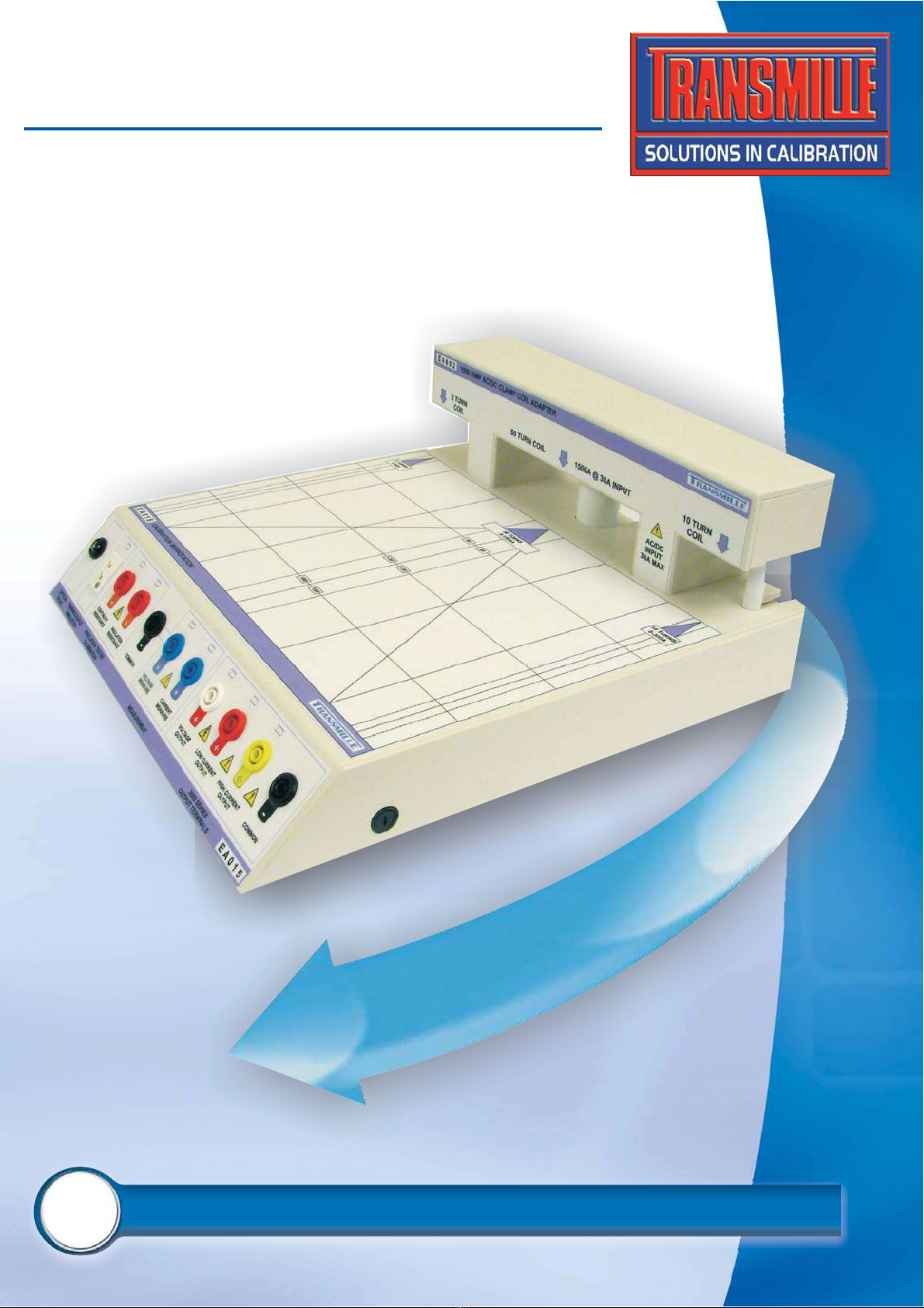
EA015 MULTI FUNCTION WORKSTATION...................................................................................................4
Design Notes ....................................................................................................................................5
Clamp Meters ..................................................................................................................5
Insulation Testers...........................................................................................................5
Process Control Calibrators..........................................................................................5
Digital Thermometers.....................................................................................................6
Optical Tachometers ......................................................................................................6
Features ............................................................................................................................................6
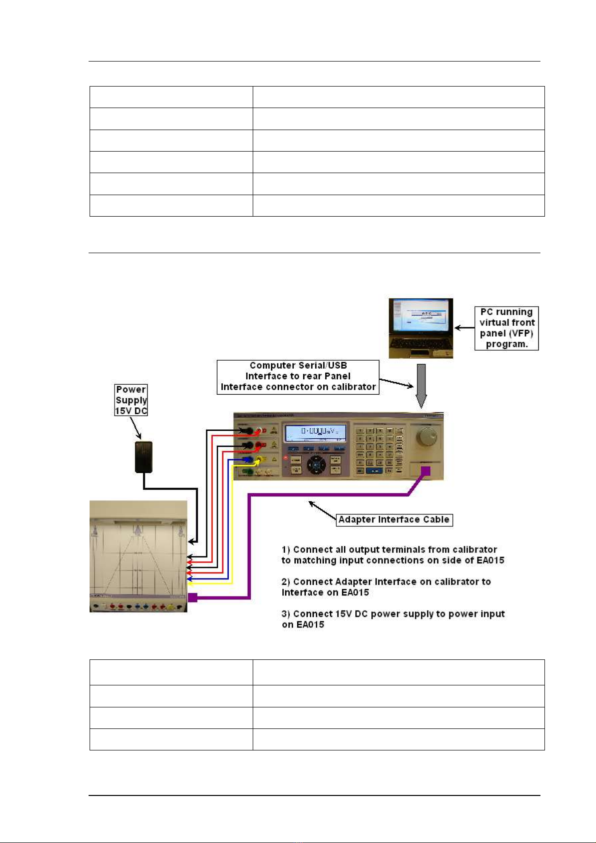
Using the EA015 with the Virtual Front Panel Software..............................................................8
Installing the Software ...................................................................................................8
Selecting a COM Port .....................................................................................................8
Operation of the Virtual Front Panel.............................................................................9
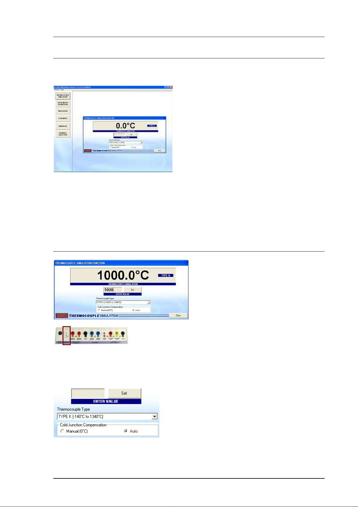
Functions : Thermocouple Simulation.........................................................................9
Functions : Tachometer Calibration...........................................................................10
Functions : Insulation Resistance ..............................................................................10
Functions : Insulation Test Voltage............................................................................11
Functions : Continuity Resistance & Current............................................................11
Functions : mA & mV Measurement...........................................................................12
STEP 1 : Enter an output value ...................................................................................13
STEP 2 : Setting to DC or AC.......................................................................................14
STEP 3 : Select a function ...........................................................................................14
STEP 4 : Select a Voltage / Current output ................................................................14
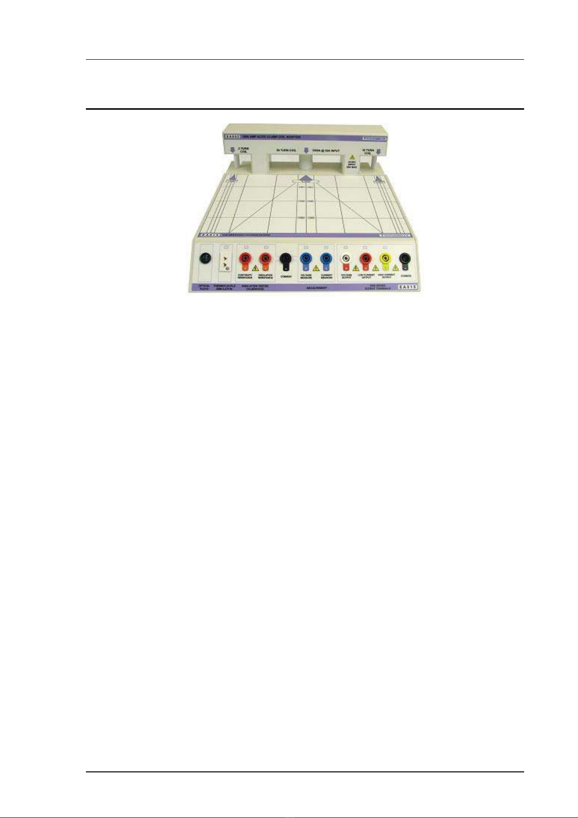
Terminals.......................................................................................................................15
STEP 5 : Set Output......................................................................................................16
Changing Output Values..............................................................................................16
Specifications.................................................................................................................................17
Care & Maintenance.......................................................................................................................18
Cleaning the Adapter.................................................................................................................18
Handling Precautions................................................................................................................18
Servicing Information................................................................................................................18

EA015 MULTI FUNCTION WORKSTATION
OPERATION MANUAL
Transmille Ltd. Page 4
EA015 Multi Function Workstation
The multi function workstation provides a central work area with all connections routed
conveniently to remote terminals mounted at the front of the adapter.
The adapter extends the capabilities of the calibrator to include :
2 / 10 / 50 TURN CLAMP COIL
INSULATION RESISTANCE OUTPUT
CONTINUITY RESISTANCE OUTPUT
INS. TEST VOLTAGE MEASUREMENT
CONTINUITY CURRENT MEASUREMENT
OPTICAL TACHOMETER CALIBRATION
THERMOCOUPLE SIMULATION
VOLTAGE MEASUREMENT : 3 RANGES
CURRENT MEASUREMENT TO 30mA
CALIBRATOR OUTPUT ROUTING :
VOLTAGE, CURRENT AND HIGH CURRENT TO
DEDICATED WORKSTATION TERMINALS

EA015 MULTI FUNCTION WORKSTATION
OPERATION MANUAL
Transmille Ltd. Page 5
Design Notes
Incorporating the advanced clamp coil, thermocouple
simulation and tachometer calibration adapters as well as
process control source / measure capabilities, this workstation
adapter provides a versatile platform for efficient calibration of a
wide range of equipment.
Selection of the specific functions on the workstation requires use of either the EA015
Workstation adapter virtual front panel software (supplied) or use of ProCal software
procedure wizards to create procedures with built in commands for setting up the adapter
functions.
NOTE : The supplied virtual front panel software or ProCal software (optional) must
be used to set output functions.
Clamp Meters
Using the built in 2, 10 and 50 turn coils, clamp meters can be accurately and quickly
calibrated. Using a high accuracy balanced design both wound (AC only) & Magnetic field
(hall effect) AC/DC clamp meters can be calibrated. Three coils in one provide the ability to
calibrate a wide range of coils, from small lower clamps down to 10mm jaw diameter to larger
2000A clamps.
Insulation Testers
Insulation tester calibration is a common requirement and is now easy to perform using the
workstation. Insulation to 2GOhms @ 1000V and continuity to 1kOhm is available from
dedicated terminals. Using the measurement capabilities of the adapter interface, the
workstation also provides insulation test voltage measurement to 1000V and continuity
current measurement.
Process Control Calibrators
Source/measure process control calibrators are commonplace in industry and previously
required several references to calibrate. The workstation integrates all the functions required
to both source and measure the required signals.

EA015 MULTI FUNCTION WORKSTATION
OPERATION MANUAL
Transmille Ltd. Page 6
Digital Thermometers
Digital thermometers can be easily calibrated accurately using the workstation’s built in
thermocouple simulation output with automatic cold junction compensation.
NOTE : The EA015 Workstation adapter requires the use of thermocouple compensation
cables for connection between the adapter and the digital thermometer (UUT)
Optical Tachometers
Using a high intensity LED light source, optical tachometers can be calibrated quickly and
easily using the workstation.
Features
Functions of the terminal connections :
EA015 Output / Input Function
Optical Tacho Optical Tachometer Calibration Source (LED)
Thermocouple Simulation Thermocouple Simulation Output
(requires compensating leads)
Continuity Resistance Continuity Resistance Output /
Continuity Current Input
Insulation Resistance Insulation Resistance Output /
Insulation Test Voltage Input
Common Common for Continuity Resistance, Insulation
Resistance, Voltage Measure and Current
Measure

EA015 MULTI FUNCTION WORKSTATION
OPERATION MANUAL
Transmille Ltd. Page 7
Voltage Measure DC Voltage Measurement Input
Current Measure DC Current Measurement Input
Voltage Output Voltage output from calibrator
Low Current Output Current output from calibrator (to 2A)
High Current Output Current output from calibrator (to 30A)
Common Common for calibrator output terminals
Connection Recommendations
To connect the EA015 Multi function workstation to the 3000 Series multi product calibrator, follow
the connection diagram below :
EA015 Output / Input Function
Power Supply 15V Adapter Power Supply
Calibrator Outputs 3000 Series Voltage & Current Outputs
Adapter Interface Adapter control interface from calibrator

EA015 MULTI FUNCTION WORKSTATION
OPERATION MANUAL
Transmille Ltd. Page 8
Using the EA015 with the
Virtual Front Panel Software
The EA015 workstation adapter should be connected as shown above.
The main terminals from the calibrator should be connected to the corresponding
terminals on the side of the adapter.
The adapter interface on the calibrator should be connected to the adapter
interface on the EA015 Workstation adapter.
The 15V external power supply should also be connected to the power socket of
the EA015 workstation adapter.
Installing the Software
Insert the CD which is supplied with the EA015 workstation adapter – this should
autorun and install the software.
Once installed run the software by clicking START > ALL PROGRAMS > EA015
Workstation Adapter
Selecting a COM Port
On starting the virtual front panel for the first time, a COM port selection screen will
be displayed. Click on the COM port that is connected to your 3000 Series calibrator
to continue.
If you are using a laptop to connect to the calibrator, the COM port will usually
be COM 1. A desktop computer will usually be COM 2.

EA015 MULTI FUNCTION WORKSTATION
OPERATION MANUAL
Transmille Ltd. Page 9
Operation of the Virtual Front Panel
Once the correct COM port is selected, the calibrator will be detected, and the main
screen displayed :
The main functions of the workstation are :
Thermocouple Simulation
Tachometer Calibration
Insulation Resistance & Voltage
Continuity Resistance & Current
mA & mV Measurement
Terminal Switching
Functions : Thermocouple Simulation
Connect temperature meter to thermocouple connector on workstation using
thermocouple compensating cables for the correct thermocouple type. Select
a thermocouple type from the drop down list. Set manual or automatic cold junction.
Enter a temperature in the box marked ENTER VALUE, then click SET. Note if the
temperature is outside the range available, a message will be displayed.

EA015 MULTI FUNCTION WORKSTATION
OPERATION MANUAL
Transmille Ltd. Page 10
Functions : Tachometer Calibration
Enter an RPM value in the box marked ENTER VALUE, the press the SET button.
The tachometer LED will illuminate – point the optical tachometer at the LED.
Note : The workstation RPM output must be set using the virtual front panel software – the
3000 Series front panel function cannot be used.
Functions : Insulation Resistance
Select the INSULATION RESISTANCE tab
Connect meter to terminals marked Insulation resistance. Select a resistance by
either :
1 : Selecting a value using the up/down buttons
2. Entering a value (in M Ohms) in the box marked
Use the F.S. button to set to 199999
Use the zero button to jump directly to ZERO

EA015 MULTI FUNCTION WORKSTATION
OPERATION MANUAL
Transmille Ltd. Page 11
Functions : Insulation Test Voltage
Select the INSULATION TEST VOLTAGE tab
Connect meter to terminals marked Insulation resistance.
1 : Select a voltage range using the range buttons
2. Apply voltage from the Insulation tester
Functions : Continuity Resistance & Current
Connect meter to terminals marked continuity resistance.
Function will default to 1 Ohm range, with continuity current measurement. Select
continuity resistance as required by clicking the buttons available.
Note : Continuity current is available on the 1 Ohm range only

EA015 MULTI FUNCTION WORKSTATION
OPERATION MANUAL
Transmille Ltd. Page 12
Functions : mA & mV Measurement
Connect meter to terminals marked voltage measure or current measure as required
Select current or voltage range as appropriate – voltage / current will be displayed
on the virtual front panel display.
Functions : Terminal / Coil Switching
This function requires the calibrator to be connected to the
workstation using the side terminals, shown left
This function allows the calibrator output to be controlled for voltage and either direct
current or current via the 2/10/50 turn coil. The current output can be routed through
the coil for clamp meter calibration.

EA015 MULTI FUNCTION WORKSTATION
OPERATION MANUAL
Transmille Ltd. Page 13
The output panel, shown left, allows the user to select a
value to output and then automatically set the calibrator
output and switch to the appropriate terminals / coil output
on the workstation adapter.
STEP 1 : Enter an output value
The output value is entered using the keypad. Micro or milli can be selected using
the buttons provided :
micro milli
Numeric buttons 0-9 and decimal point – use these to enter a
value.
Set positive or negative value – note a number must be
entered first before clicking this Button.
Backspace – use this to erase the last character
entered in the output value box.

EA015 MULTI FUNCTION WORKSTATION
OPERATION MANUAL
Transmille Ltd. Page 14
STEP 2 : Setting to DC or AC
Use the DC button to set to DC, or enter a frequency using the keypad, then press
Hz to set an AC frequency.
Frequency display within main window – DC or a frequency,
eg. 50Hz.
STEP 3 : Select a function
Select either Voltage or Current by using the buttons provided :
Volts Amps
STEP 4 : Select a Voltage / Current output
For voltage, once the output value is set and V is pressed, proceed directly to
STEP 5.
If the value entered is a
current, the choice of where
this should be output from is
available using the buttons
shown right. The available
buttons will flash, indicating
that a choice should be made.
50 Turn Coil : Available for currents between 100A and 1500A

EA015 MULTI FUNCTION WORKSTATION
OPERATION MANUAL
Transmille Ltd. Page 15
10 Turn Coil : Available for currents between 10A and 300A
2 Turn Coil : Available for currents between 4A and 60A
Terminals
Available for currents between
0A and 2A (Low Current Terminals)
2A and 30A (High Current Terminals)

EA015 MULTI FUNCTION WORKSTATION
OPERATION MANUAL
Transmille Ltd. Page 16
Note : Only the outputs which are available for current value entered are
enabled – if the button is not available (greyed out) this means it is not
possible to output this value using that specific output (eg. It is not possible to
output 2A using the 50 turn coil – minimum value from 50 turn coil is 100A :
2A x 50 turns).
STEP 5 : Set Output
Once the output value is set, press the enter button to set the
output.
Use the STANDBY and OUTPUT ON buttons to control the
output.
The Autoset Output On option allows the output to be
automatically switched on when a value is entered. If this option is unchecked, the
output will not be switch on automatically, but left set in standby.
When high voltage (>40V) is output, the
Autoset Output ON is not available.
Changing Output Values
If the output value is changed, the VFP program will check if this is possible using
the current range selected. If it is not possible to output this value, the current output
buttons will flash to indicate that a different output should be selected.
Note : Only the outputs which are available for current value entered are enabled,
e.g.
Example : 1000A Output Set
50 TURN COIL (to 1500A) enabled,
all other modes disabled as not
possible with 1000A Selected.
10 TURN COIL – Max. Output = 300A
2 TURN COIL – Max. Output = 60A
TER
MINALS
–
Max. Output
=
30A

EA015 MULTI FUNCTION WORKSTATION
OPERATION MANUAL
Transmille Ltd. Page 17
Specifications
GENERAL SPECIFICATIONS
Output
Connections 9x 4mm Safety Terminals
1x thermocouple socket (neutral copper)
1x Optical LED output
Control
Interface ‘D’ type connector for use with
3000 Series Adapter Interface
Power Supply 15V External Power Supply Unit
PERFORMANCE SPECIFICATIONS
Clamp Meter Calibration 2 / 10 / 50 Turn
Up to 1500A (Simulated)
Insulation Tester Calibration
Continuity Resistance
Insulation Resistance
Continuity Current Measurement
Insulation Test Voltage Measurement
Up to 1kOhm
Up to 2Gohms / 1000V
Up to 300mA
Up to 1000V
Digital Thermometer Calibration J, K, T, R, S, B, N, E
Process Control Calibration
DCV Measurement
DCI Measurement
DCV/I Source from calibrator
100mV/1V/10V Ranges
30mA Range
AC/DC 1000V • 30A
Optical Tachometer Calibration Range : 60 to 60,000 RPM

EA015 MULTI FUNCTION WORKSTATION
OPERATION MANUAL
Transmille Ltd. Page 18
Care & Maintenance
The only maintenance instructions for the adapter is periodic cleaning. See below for
details on the cleaning procedure and precautions for handling.
Cleaning the Adapter
To keep the external enclosure of the adapter in good condition, clean the outer
case with a soft cloth. Do not use any liquids in cleaning the enclosure – removal of
surface dust is all that is recommended.
CAUTION
Do not use cleaning fluids or solvents for cleaning as these may damage the
enclosure and affect the plastic materials used in the transconductance amplifier.
Handling Precautions
The adapter is designed for mechanical stability, but should not be subjected to
excessive shock or be dropped. Transportation is recommended using the original
packaging with avoidance of extreme changes of temperature.
Servicing Information
The adapter is provided certified from the factory, and uses precision components
that are not user repairable. If the instrument is damaged it should be returned to the
factory for repair and recalibration.
Table of contents
Other Transmille Adapter manuals