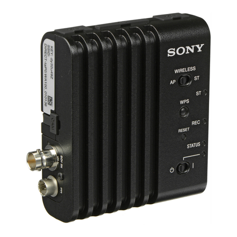
Sony Digital BETACAM CA-701 User manual

CAMERA ADAPTOR
CA-701
MAINTENANCE MANUAL
1st Edition
Serial No. 10001 and Higher (Except Japan)
Serial No. 30001 and Higher (Japan)

!WARNING
This manual is intended for qualified service personnel only.
To reduce the risk of electric shock, fire or injury, do not perform any servicing other than that
contained in the operating instructions unless you are qualified to do so.Refer all servicing to
qualified service personnel.
!WARNUNG
Die Anleitung ist nur für qualifiziertes Fachpersonal bestimmt.
Alle Wartungsarbeiten dürfen nur von qualifiziertem Fachpersonal ausgeführt werden.Um die
Gefahr eines elektrischen Schlages, Feuergefahr undVerletzungen zu vermeiden, sind bei
Wartungsarbeiten strikt die Angaben in der Anleitung zu befolgen. Andere als die angegeben
Wartungsarbeiten dürfen nur von Personen ausgeführt werden, die eine spezielle Befähigung
dazu besitzen.
!AVERTISSEMENT
Ce manual est destiné uniquement aux personnes compétentes en charge de l’entretien. Afin
de réduire les risques de décharge électrique, d’incendie ou de blessure n’effectuer que les
réparations indiquées dans le mode d’emploi à moins d’être qualifié pour en effectuer d’autres.
Pour toute réparation faire appel à une personne compétente uniquement.

1
CA-701
Table of Contents
Manual Structure
Purpose of this manual ......................................................................................... 3(E)
Contents ................................................................................................................ 3(E)
Relative manual .................................................................................................... 3(E)
1. Service Overview
1-1. System Configuration.............................................................................1-1(E)
1-2. Matching Connectors .............................................................................1-1(E)
1-3. Connector Input/Output Signals.............................................................1-2(E)
1-4. Setting the Switches on Board ...............................................................1-3(E)
1-4-1. AD-119 board........................................................................1-3(E)
1-4-2. DA-98 board..........................................................................1-3(E)
1-5. Notes on System Connection .................................................................1-4(E)
1-6. Board Layout..........................................................................................1-4(E)
1-7. Replacement of Main Parts ....................................................................1-5(E)
1-7-1. Removal of Cabinet...............................................................1-5(E)
1-7-2. Replacement of 40-pin Connector ........................................1-6(E)
1-7-3. Removal/Installation of Flexible Card Wires
on AD-119 Board..................................................................1-7(E)
1-7-4. AD-119 Board Replacement .................................................1-8(E)
1-7-5. CN-1233 Board Removal......................................................1-8(E)
1-8. Notes on Service ....................................................................................1-9(E)
1-8-1. Power Circuit Breaker...........................................................1-9(E)
1-8-2. Notes on Replacement of V Shoe .........................................1-9(E)
1-9. Tool ........................................................................................................1-9(E)
1-10. Notes on Spare Parts ............................................................................1-10(E)
2. Electrical Alignment
2-1. General Information for Electrical Adjustment .....................................2-1(E)
2-1-1. Notes for Adjustment ............................................................2-1(E)
2-1-2. Equipment/Fixtures ...............................................................2-1(E)
2-2. Video System Adjustment......................................................................2-1(E)
2-2-1. VCO Free-run Frequency Adjustment ..................................2-1(E)
2-3. Audio System Adjustment .....................................................................2-2(E)
2-3-1. D/A Level Adjustment ..........................................................2-2(E)
2-3-2. Output Limiter Adjustment ...................................................2-2(E)
2-3-3. AGC Level Adjustment.........................................................2-3(E)
2CA-701
3. Spare Parts
3-1. Exploded Views ..........................................................................................3-1
3-2. Electrical Parts List .....................................................................................3-5
4. Semiconductor Pin Assignments
5. Block Diagrams
Overall Block ............................................................................................5-1
AD-119 Block ........................................................................................... 5-2
DA-98 Block ............................................................................................. 5-3
DIF-41 Block ............................................................................................5-4
RE-123 Block............................................................................................5-5
6. Schematic Diagrams
CN-1233 Board ......................................................................................... 6-1
AD-119 Board...........................................................................................6-4
DA-98 Board.............................................................................................6-8
DIF-41 Board ..........................................................................................6-12
RE-123 Board .........................................................................................6-14
DP-234 Board .........................................................................................6-17
MB-651 Board ........................................................................................6-18
Frame Wiring ..........................................................................................6-20
7. Board Layouts
AD-119 Board...........................................................................................7-1
DA-98 Board.............................................................................................7-1
DIF-41 Board ............................................................................................7-2
RE-123 Board ...........................................................................................7-2
MB-651 Board ..........................................................................................7-3
DP-234 Board ...........................................................................................7-3
HN-225 Board...........................................................................................7-3
CN-1233 Board ......................................................................................... 7-4
SW-819 Board ..........................................................................................7-4
CN-1339 Board ......................................................................................... 7-4

3 (E)
CA-701
Purpose of this manual This manual is the maintenance manual for Camera Adaptor CA-701.
Contents The followings are summaries of the each section for understanding the manual.
Section 1 Service Overview
Describes information about connection and how to replace the main parts.
Section 2 Electrical Alignment
Describes electrical adjustment.
Section 3 Spare Parts
Describes parts list, exploded view, packing materials and supplied accessories list
used in the unit.
Section 4 Semiconductor Pin Assignments
Describes function diagrams and pin names of semiconductor used in the unit.
Section 5 Block Diagrams
Describes overall block diagram and the block diagrams for every circuit board.
Section 6 Schematic Diagrams
Describes schematic diagrams for every circuit.
Section 7 Board Layouts
Describes board layouts for every circuit.
Relative manual Besides this maintenance manual, the following manual is available for this unit.
• Operation Manual (Supplied with this unit)
This manual is necessary for application and operation of this unit.
Manual Structure


1-1 (E)
CA-701
Section 1
Service Overview
1-1. System Configuration
1-2. Matching Connectors
When external cables are connected to the connector on the outside panel during maintenance, the
hardware listed below (or the equivalents) must be used.
Panel indication Matching cable connector/cable
Connector Sony part No.
SDI OUT 1, 2 BNC 1-560-069-11
AUDIO IN CH-3, 4 XLR 3P, MALE 1-508-084-00
AUDIO OUT XLR 5P, FEMALE 1-508-370-11
DC IN XLR 4P, FEMALE 1-508-362-00
DC OUT ROUND TYPE 4P, MALE 1-566-425-11
MIC, MIXER etc.
AC-550
BP-L60
BP-L90
VIDEO(BNC)CABLE
AUDIO CABLECH-3
CH-4
DVW-700/700WS/700P/700WSP
DVW-250/250P
DC CORD
CA-701

1-2 (E) CA-701
1-3. Connector Input/Output Signals
INPUT
AUDIO IN CH-3, 4 –60 dBu/+4 dBu
(0 dBu=0.775 Vrms)
OUTPUT
AUDIO OUT 0 dBu (600 Ωterminated)
HEADPHONE OUT 8 Ωload, –26 dBu
SDI OUT 1,2 75 Ωterminated, 0.8 V p-p,
270 Mbps
AUDIO OUT:XLR,5-pin (male)
<External view>
Pin No. Signal
1 GND
2 L CH (X)
3 L CH (Y)
4 R CH (X)
5 R CH (Y)
DC IN:XLR,4-pin (male)
<External view>
Pin No. Signal
1 UNREG GND
2—
3—
4 EXT DC (+)
12 V (10.5–17V)
14
DC OUT:DIN, 4-pin (female)
<External view>
Pin No. Signal
1 UNREG GND
2—
3—
4 DC OUT
14
23
1-3. Connector Input/Output Signal
12345

1-3 (E)
CA-701
A side
A
1
2
3
4
5
6
7
BCDEFGHJKLM
N
S1-1
S1-2
S1-3
S1-4
S201
S1
CN1
S101
ON OFF
1-4. Setting the Switches on Board
1-4-1. AD-119 board
Ref No. Name Description Factory setting
S103 CH-3 LIM ON-OFF Selects whether to turn on or off the limiter OFF
in the CH-3 audio input stage.
ON : CH-3 Audio INPUT LIMITER ON
OFF: CH-3 Audio INPUT LIMITER OFF
S153 CH-4 LIM ON-OFF Selects whether to turn on or off the limiter OFF
in the CH-4 audio input stage.
ON : CH-4 Audio INPUT LIMITER ON
OFF: CH-4 Audio INPUT LIMITER OFF
1-4-2. DA-98 board
Ref No. Name Description Factory setting
S1 — Factory use All OFF
S101 OUTPUT LIM ON-OFF Selects whether to turn on or off the output limiter. ON
ON : Audio OUTPUT LIMITER ON
OFF: Audio OUTPUT LIMITER OFF
S201 POWER ON BLOCK Selects whether to power in the audio or AUDIO
the SDI block when the power switch is turned to SEL.
Audio block only
SDI block only*1
*1 : No display on the audio level meter LCD when only SDI block is powered .
1-4. Setting the Switches on Board
S153
OFF ON
OFF ONS103
B side
GFE
DCBA
1
2
3

1-4 (E) CA-701
1-5. Notes on System Connection
It is necessary to check the following items in the DVW-700/700WS/700P/700WSP when connect them
to the CA-701. Perform the measures shown in the figure when the use conditions are not matched.
Check item Use condition Measures Applicable serial No.
AT-84 board in the DVW-700 ROM(IC16) version is ROM replacement Serial No. 10001 to 10196
/700WS /700P/700WSP. V2.10 or higher. (P/N:8-759-390-05) [DVW-700]
Serial No. 90001 to 90015
[DVW-700]
SY-191 board in the DVW-700 ROM(IC1) version is IC replacement SerialNo. 40001 to 40250
/700WS/700P/700WSP. V1.10 or higher. (QFP type [DVW-700P]
P/N:8-759-388-93) Serial No. 90001 to 90021
(EPROM type [DVW-700P]
P/N:8-759-398-40) Serial No. 10001 to 10065
[DVW-700WS]
Serial No. 90001 to 90002
[DVW-700WS]
Serial No. 40001 to 40415
[DVW-700WSP]
1-6. Board Layout
Board name Circuit function Location No.
AD-119 A/D converter 3
CN-1176 Connector 5
CN-1233 Connector 1
CN-1339 Connector 11
DA-98 D/A converter, System control 9
DIF-41 Serial digital interface 6
DP-234 Display 4
HN-225 Harness 2
MB-651 Mother board 10
RE-123 Regulator, DC-DC converter 7
SW-819 Switch 8
1-5. Notes on System Connection
1-6. Board Layout
5
3
9
1
0
!-
8
7
4
2
6

1-5 (E)
CA-701
1-7. Replacement of Main Parts
1-7-1. Removal of cabinet
1-7. Replacement of Main Parts
Coaxial cables
Outside panel
1. Loosen three screws and
remove the outside panel.
(The screws are not pulled out.)
2. Disconnect the two coaxial cables.
Inside panel
Loosen three screws and
remove the inside panel.
(The screws are not pulled out.)

1-6 (E) CA-701
40-pin connector
CN-1176 board
40 spots
1-7-2. Replacement of 40-pin connector
1. Remove the two screws (–).
2. Remove the six screws and remove the 40-pin bracket.
3. Desolder the CN-1176 board and remove the 40-pin
connector.
4. Solder the new 40-pin connector on the CN-1176
board.
5. Attach the 40-pin connector in the reverse order of
removal steps.
6. Check that the 40-pin connector is free by hand.
1-7. Replacement of Main Parts
Screws (–)
(M2.6× 5)
40-pin bracket
Screws (M2.6× 5)
Screws
(M2 × 3)
Screws
40-pin connector

1-7 (E)
CA-701
1-7-3. Removal/Installation of flexible card wires on AD-119 board
The two flexible card wires are used between the AD-119 board and MB-651 board.
Be careful not to bend these wires. This shortens the wire life.
Disconnecting
1. Turn off the power.
2. Slide portion A in the direction indicated by the arrow, unlock it, and pull out the flexible card wires.
Connecting
n
• Be careful not to insert the flexible card wire obliquely.
• Check that the conductive surface of the flexible card wire is not so soiled with dust.
1. Slide portion A in the direction indicated by the arrow and insert the flexible card wires tightly into
each connector with the conductive surface of these wires put down.
2. Slide portion a in the reverse direction of the arrow and lock each connector.
1-7. Replacement of Main Parts
Portion A
Portion A
Flexible card wires
Inside panel

1-8 (E) CA-701
1-7-5. CN-1233 Board Removal
The three flexible card wires are used CN-1233 board.
Be careful not to bend these wires. This shortens the wire life.
1. Remove the three screws and remove the outside
panel.
2. Remove the VR knob and disconnect the connector
CN3 on the CN-1233 board.
3. Remove the four screws.
4. Remove the two screws fixing the connector CH-3 and
CN-4.
5. Remove the two screws. And then remove the CN-
1233 board from the outside panel
1-7-4. AD-119 Board Replacement
Removal
1. Remove the three screws and open the inside panel.
2. Disconnect the flexible card wires CN1,2 and connec-
tor CN3.
(Refer to section 1-7-3, how to disconnecting the
flexible card wires.)
3. Remove the seven screws fixing the ADA-119 board.
4. Remove the screws fixing the control knob and
remove the control knob from the inside panel.
5. Remove the AD-119 board from the inside panel
Note during installation
After attaching the AD-119 board, check the key-tops are
attached with it.
1-7. Replacement of Main Parts
CN2
CN1
CN3
Screws
(B2 ×3)
Control knob
Hexagon wrench
AD-119 board
Key-top
CN-1233board
VR knob
Outside panel
CN3
Screws
(M2×3)
P2.6 ×5
(type 1)
P2.6 ×5 (type 1)
P2.6 ×5
(type 1)
CH-4 connector
CN-1233 board
CH-3 connector

1-9 (E)
CA-701
1-8. Notes on Service
1-8-1. Power circuit breaker
Excessive current in the internal circuitry, whatever the
cause, will trip the internal circuit breaker, automatically
cutting off the power. After checking that the problem has
been corrected, press the button shown in the figure. The
power should come on again.
1-8-2. Notes on replacement of V shoe
It is necessary to attach the V shoe on the main chassis
with precisely position when will attach the CA-701 on the
DVW-700 in absolute contact.
Tighten the three screws sequentially in the figure when
attach the V shoe on the main chassis. When the V shoe is
replaced, check that the specification is met.
Specification: a–b = 0 ±0.1 mm
1-9. Tool
Extension board BC-155: J-6421-550-A
RE-123 board
ab
12
3
1-8. Notes on Service
1-9. Tool

1-10 (E) CA-701
1-10. Notes on Spare Parts
1. Safety Related Components Warning
Components marked !are critical to safe opera-
tion. Therefore, specified parts should be used in
the case of replacement.
2. Standardization of Parts
Some repair parts supplied by Sony differ from
those used for the unit. These are because of parts
commonality and improvement.
Parts list has the present standardized repair parts.
3. Stock of Parts
Parts marked with “o” at SP(Supply Code)
column of the spare parts list may be not stocked.
Therefore, the delivery date will be delayed.
4. Units Representation
The following represented units are changed or
omitted in writing.
Units Representation
Capacitance µFuF
Inductance µHuH
Resistance ΩAbbreviation
Temperature °C XXX-DEG-C
5. Destination Representation
The part indicated “For J/SY” in the spare parts
list is used in the unit written below.
For J : The part is used in a unit for Japan.
For SY : The part is used in a unit for regions
except the above countries.

2-1(E)
CA-701
Secton 2
Electrical Alignment
2-1. General Information for Electrical
Adjustment
2-1-1. Notes for adjustment
• When a board is extracted, turn off the power of the CA-
701 and a video camera.
• Before adjustment, turn the power on and warm up the
unit for about 10 munites.
2-1-2. Equipment/Fixtures
Equipment/Fixtures Model
Digital betacam camcorder DVW-700/700WS/700P/700WSP
AC adapter or Battery Sony AC-550/550CE or equivalent
Oscilloscope Tektronix 2465B or equivalent
Audio analyzer Tektronix AA501A (OP.02) or
equivalent
Audio oscillator Tektronix SG-5010 or equivalent
Frequency counter Advantest TR5821AK orequivalent
2-2. Video System Adjustment
2-2-1. VCO Free-run Frequency Adjustment
Preparation
• Connect TP1 (D-2) and E2 (E-2) on the DIF-41 board
using a shorting clip.
And warm up the unit for about 10 minutes.
Adjustment procedure
1. Equipment : Frequency counter
Test point : TP2 (E-3)/DIF-41 board
Adjustment point : 1 RV1 (D-3)/DIF-41 board
Specification : 27.0 ±0.1 MHz
Setting after adjustment
• Disconnect the shout clip.
321
A
D
E
B
C
DIF-41 Board (A side)
TP1
E2
TP2
RV1

2-2(E) CA-701
2-3. Audio System Adjustment
2-3-1. D/A Level Adjustment
Preparation
• S103 (E-3) /AD-119 board:OFF
• S101 (M-7) /DA-98 board:OFF
• MONITOR switch/inside panel:CH-3/-4
• OUTPUT switch/inside panel (DVW-700/700WS/700P/
700WSP) :BARS
• Sets to record the -20 dBs in 1 kHz test signal of an
internal signal generator using diagnostic mode of the
DVW-700/700WS/700P/700WSP. (Refer to section 3-2.
DIAGNOSTIC MODE of the DVW-700/700WS/700P/
700WSP MAINTENANCE MANUAL Part 1.)
Adjustment procedure
1. MONITOR switch:MONO (CH-3)
2. Equipment : Audio analyzer
Test point : AUDIO OUT connector
Adjustment point : 1 RV101 (J-3)/DA-98 board
Specification : 0 ±0.2 dBm (600 Ω)
3. MONITOR switch:MONO (CH-4)
4. Equipment : Audio analyzer
Test point : AUDIO OUT connector
Adjustment point : 1 RV151 (J-7)/DA-98 board
Specification : 0 ±0.2 dBm (600 Ω)
Setting after adjustment
• Reset switches and DIAGNOSTIC mode to the former
settings.
VTR MENU-4
VTR MODE SELECT-2
1. AUDIO OUT (F/R)EE
2. AUDIO OUT (CH)CH1/2
3. AU-REC CH3/CH4ON
4. AU-REC 1kHz –20dB
5. AU-EMPHASIS OFF
VF screen
2-3-2. Output Limiter Adjustment
Preparation
• S101 (M-7) /DA-98 board:ON
• S103 (E-3) /AD-119 board:OFF
• S153 (E-2) /AD-119 board:OFF
• LINE/MIC CH-3 switch/outside panel:MIC
• MONITOR switch/inside panel:CH-3/-4
• AUDIO SELECT CH-3 switch/inside panel:MANUAL
• AUDIO SELECT CH-4 switch/inside panel:MANUAL
• OUTPUT switch/inside panel (DVW-700/700WS/700P/
700WSP) :CAM
Adjustment procedure
1. Connect the output of audio oscillator (SG-5010) to
the AUDIO IN CH-3 connector of CA-701.
Test point : AUDIO IN CH-3 connector
Specification : 1 kHz, -60 dBu
2. Equipment : Audio analyzer
Test point : AUDIO OUT connector
Adjustment point : 1 AUDIO LEVEL volume (CH-
3) /inside panel
Specification : 0 ±0.2 dBm (600 Ω)
3. Set output level of audio oscillator as follows.
Test point : AUDIO IN CH-3 connector
Specification : 1 kHz, -40 dBu
4. Test point : AUDIO OUT connector
Adjustment point : 1 RV2 (K-7) /DA-98 board
Specification : +9.0 ±0.2 dBm (600 Ω)
Setting after adjustment
• Reset switches to the former settings.
2-3. Audio System Adjustment

2-3(E)
CA-701
2-3-3. AGC Level Adjustment
Preparation
• S103 (E-3) /AD-119 board:OFF
• S153 (E-2) /AD-119 board:OFF
• LINE/MIC CH-3 switch/outside panel:LINE
• MONITOR switch/inside panel:CH-3/-4 and MONO
(CH-3)
• AUDIO SELECT CH-3 switch/inside panel:AUTO
Adjustment procedure
1. Connect the output of audio oscillator (SG-5010) to
the AUDIO IN CH-3 connector of CA-701.
Test point : AUDIO IN CH-3 connector
Specification : 1 kHz, +4.0 dBu
2. Equipment : Audio analyzer
Test point : AUDIO OUT connector
Adjustment point : 1 RV1 (F-3)/AD-119 board
Specification : 0 ±0.2 dBm (600 Ω)
Setting after adjustment
• Reset switches to the former settings.
RV151
RV2
6A
7 54321
B
C
D
J
K
L
M
N
E
F
G
H
S101
DA-98 Board (A side)
RV101
3
A
21
B
C
D
E
F
G
S153 S103
RV1
AD-119 Board (B side)
2-3. Audio System Adjustment
Table of contents
Other Sony Adapter manuals

Sony
Sony XA-CC1 User manual

Sony
Sony AC-UD11 User manual

Sony
Sony PCGA-BA2 User manual

Sony
Sony MSAC-FD1A User manual

Sony
Sony NVA-CU3 Operation and maintenance manual

Sony
Sony TDM-MP10 User manual

Sony
Sony PRSA-CC1 User manual

Sony
Sony BKM-FW32 User manual

Sony
Sony BKM-FW50 User manual

Sony
Sony BDV-E770W (UWA-BR100) User manual