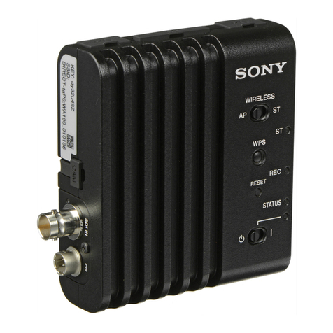
Sony HDFX200 User manual

HD DIGITAL TRIAX CCU ADAPTOR
HDFX200
MAINTENANCE MANUAL
1st Edition

警告
このマニュアルは, サービス専用です。
お客様が, このマニュアルに記載された設置や保守, 点検, 修理などを行うと感電や火災,
人身事故につながることがあります。
危険をさけるため, サービストレーニングを受けた技術者のみご使用ください。
WARNING
This manual is intended for qualified service personnel only.
To reduce the risk of electric shock, fire or injury, do not perform any servicing other than that
contained in the operating instructions unless you are qualified to do so. Refer all servicing to
qualified service personnel.
WARNUNG
Die Anleitung ist nur für qualifiziertes Fachpersonal bestimmt.
Alle Wartungsarbeiten dürfen nur von qualifiziertem Fachpersonal ausgeführt werden. Um die
Gefahr eines elektrischen Schlages, Feuergefahr und Verletzungen zu vermeiden, sind bei
Wartungsarbeiten strikt die Angaben in der Anleitung zu befolgen. Andere als die angegeben
Wartungsarbeiten dürfen nur von Personen ausgeführt werden, die eine spezielle Befähigung
dazu besitzen.
AVERTISSEMENT
Ce manual est destiné uniquement aux personnes compétentes en charge de l’entretien. Afin
de réduire les risques de décharge électrique, d’incendie ou de blessure n’effectuer que les
réparations indiquées dans le mode d’emploi à moins d’être qualifié pour en effectuer d’autres.
Pour toute réparation faire appel à une personne compétente uniquement.
Model Name Serial No.
HDFX200 (UC) 10001 and Higher
HDFX200 (CE) 40001 and Higher
HDFX200

CAUTION
Use of controls or adjustments or performance of
procedures other than those specified herein may
result in hazardous radiation exposure.
CAUTION
The use of optical instruments with this product will
increase eye hazard.
CLASS 1 LASER PRODUCT
LASER KLASSE 1 PRODUKT
LUOKAN 1 LASERLAITE
KLASS 1 LASER APPARAT
This HD Digital Triax CCU Adaptor is classified as a
CLASS 1 LASER PRODUCT.
For kundene i Norge
Dette utstyret kan kobles til et IT-strømfordelingssystem.
Attention-when the product is installed in Rack:
1. Prevention against overloading of branch circuit
When this product is installed in a rack and is
supplied power from an outlet on the rack, please
make sure that the rack does not overload the supply
circuit.
2. Providing protective earth
When this product is installed in a rack and is
supplied power from an outlet on the rack, please
confirm that the outlet is provided with a suitable
protective earth connection.
3. Internal air ambient temperature of the rack
When this product is installed in a rack, please make
sure that the internal air ambient temperature of the
rack is within the specified limit of this product.
4. Prevention against achieving hazardous
condition due to uneven mechanical loading
When this product is installed in a rack, please
make sure that the rack does not achieve hazardous
condition due to uneven mechanical loading.
5. Install the equipment while taking the operating
temperature of the equipment into consideration
For the operating temperature of the equipment, refer
to the specifications of the Operation Manual.
6. When performing the installation, keep the
following space away from walls in order to
obtain proper exhaust and radiation of heat.
Rear: 10 cm (4 inches) or more
本機をラックに設置するとき
熱の適切な排気・発散を得るために,ラックと本機の間
には,以下の空間を確保してください。
・後面 10cm 以上
HDFX200


Table of Contents
Manual Structure
Purpose of this manual....................................................................................................................5
Related manuals...........................................................................................................................5
1. Service Overview
1-1. Installation.....................................................................................................................1-1
1-1-1. Operating Environment.................................................................................................1-1
1-1-2. Outside Dimensions....................................................................................................1-1
1-1-3. Rack Mount.............................................................................................................1-1
1-2. Connectors and Cables........................................................................................................1-3
1-2-1. Connector Input/Output Signals........................................................................................1-3
1-2-2. Connection Connectors/Cables.........................................................................................1-3
1-3. Location of Printed Circuit Boards............................................................................................1-4
1-4. Circuit Description............................................................................................................1-5
1-4-1. AT-189C Board.........................................................................................................1-5
1-4-2. DM-151 Board..........................................................................................................1-5
1-4-3. DRX-13 Board..........................................................................................................1-5
1-4-4. DTX-13 Board..........................................................................................................1-5
1-4-5. ENC-149 Board.........................................................................................................1-5
1-4-6. LE-388 Board...........................................................................................................1-6
1-4-7. MB-1202 Board........................................................................................................1-6
1-5. Functions of Onboard Switches and LED Indicators.........................................................................1-7
1-5-1. DRX-13 Board..........................................................................................................1-7
1-5-2. DTX-13 Board..........................................................................................................1-7
1-6. Tools...........................................................................................................................1-8
1-7. Actions to Be Taken after Replacement of Board and IC.....................................................................1-9
1-7-1. DM-151 Board..........................................................................................................1-9
1-8. Cleaning of Connector/Cable................................................................................................1-10
1-8-1. When the Optical Connector Cleaner (Commercially Available) is Available.......................................1-10
1-8-2. When the Optical Connector Cleaner (Commercially Available) is not Available ..................................1-11
1-9. Upgrading Software Programs...............................................................................................1-13
1-9-1. Upgrading Adapter Application.......................................................................................1-13
1-9-2. Upgrading OS.........................................................................................................1-14
1-10. PLD..........................................................................................................................1-16
1-10-1. Corresponding PLD...................................................................................................1-16
1-10-2. Upgrading PLD Data..................................................................................................1-16
1-11. Circuit Protection Parts......................................................................................................1-18
1-11-1. Fuse....................................................................................................................1-18
1-12. Lead-free Solder.............................................................................................................1-19
2. Replacement of Main Parts
2-1. Location of Main Parts........................................................................................................2-1
2-2. Coaxial Cable.................................................................................................................2-2
2-2-1. Disconnecting/Connecting Coaxial Cable..............................................................................2-2
2-3. Front Panel Assembly.........................................................................................................2-3
2-4. Top Cover.....................................................................................................................2-4
HDFX200 1
2-5. LE-388 Board.................................................................................................................2-5
2-6. TRIAX Assembly.............................................................................................................2-6
2-7. DM-151 Board................................................................................................................2-7
2-8. DRX-13 Board/AT-189C Board.............................................................................................2-11
2-9. DTX-13 Board/ENC-149 Board.............................................................................................2-13
2-10. MB-1202 Board..............................................................................................................2-18
2-11. Optical Multi Cable Assembly (F)...........................................................................................2-19
2-12. Optical Multi Cable Assembly (M)..........................................................................................2-22
2-13. Power Block Assembly (D00)...............................................................................................2-25
2-14. DC Fan (Power)..............................................................................................................2-26
3. Electrical Alignment
3-1. Preparation....................................................................................................................3-1
3-1-1. Equipment and Tools...................................................................................................3-1
3-1-2. Notes on Adjustments..................................................................................................3-1
3-1-3. Connection..............................................................................................................3-1
3-2. TRIAX Transmission System Adjustment....................................................................................3-2
3-2-1. Tone Detection Frequency Adjustment................................................................................3-2
3-2-2. 1.4-MHz Demodulation Circuit Adjustment...........................................................................3-2
3-2-3. 1.0-MHz Modulation Circuit Adjustment..............................................................................3-3
4. Spare Parts
4-1. Note on Repair Parts..........................................................................................................4-1
4-2. Exploded Views...............................................................................................................4-2
4-3. Electrical Parts List............................................................................................................4-7
4-4. Supplied Accessories........................................................................................................4-61
5. Block Diagrams
Overall..................................................................................................................................5-1
6. Schematic Diagrams
AT-189C................................................................................................................................6-1
DM-151.................................................................................................................................6-5
DRX-13...............................................................................................................................6-17
DTX-13................................................................................................................................6-30
ENC-149..............................................................................................................................6-51
LE-388.................................................................................................................................6-53
MB-1202..............................................................................................................................6-54
PS-778D00............................................................................................................................6-56
RE-274................................................................................................................................6-59
Frame Wiring..........................................................................................................................6-62
HDFX200 2

7. Board Layouts
AT-189C................................................................................................................................7-1
DM-151.................................................................................................................................7-2
DRX-13.................................................................................................................................7-4
DTX-13.................................................................................................................................7-6
ENC-149................................................................................................................................7-7
LE-388..................................................................................................................................7-7
MB-1202................................................................................................................................7-8
PS-778D00..............................................................................................................................7-9
RE-274................................................................................................................................7-11
Board Parts Location..................................................................................................................7-13
HDFX200 3


Manual Structure
Purpose of this manual
This manual describes the information items that premise the service based on the components parts assuming use of
system and service engineers.
Related manuals
The following manuals are available in this model.
If this manual is required, please contact your local Sony Sales Office/Service Center.
• Operation Manual (Supplied with this unit)
This manual is necessary for application and operation of this unit.
HDFX200 5


Section 1
Service Overview
1-1. Installation
1-1-1. Operating Environment
Operating temperature: +5 ℃ to +40 ℃
Storage temperature: -20 ℃ to +60 ℃
Humidity: Non condensing
Supply voltage: AC100 V to 240 V ±10 % (50/60 Hz)
Power consumption: 4.5 A 100 V (MAX)
1. Do not put the unit in a place subject to high temperature or in a location near heat sources.
2. Do not put the unit in a place subject to excessive electric and magnetic fields.
3. Put the unit in a dry and well-ventilated place.
4. Do not put the unit in a place subject to excessive dust and mechanical shock.
5. Do not put the unit in a place subject to direct sunlight and light.
1-1-2. Outside Dimensions
135
(Unit: mm)
124 366
OPTICAL CONDITION
POWER
TRIAX ALARM
MODE
CAM
CAM TRIAX
FIBER
FAN STOP
MAIN
OPEN
SHORT
HDFX
CCU
1-1-3. Rack Mount
This unit can be mounted in a 19-inch EIA standard rack.
To mount the unit in a 19-inch EIA standard rack, create the rack following the dimensions below.
HDFX200 1-1

215
328
52.5
436
465
482.6
37.7
75
ø5 70 75 70 75
A
ø5
132.6 -0.5
+0
57.2
±
0.2
A
12
ø5 hole
SECTION A-A
16
2
(Unit: mm)
19-inch standard rack
Three units mounted
OPTICAL CONDITION
POWER
TRIAX ALARM
MODE
CAM
CAM TRIAX
FIBER
FAN STOP
MAIN
OPEN
SHORT
HDFX
CCU
OPTICAL CONDITION
POWER
TRIAX ALARM
MODE
CAM
CAM TRIAX
FIBER
FAN STOP
MAIN
OPEN
SHORT
HDFX
CCU
OPTICAL CONDITION
POWER
TRIAX ALARM
MODE
CAM
CAM TRIAX
FIBER
FAN STOP
MAIN
OPEN
SHORT
HDFX
CCU
hole
hole
HDFX200 1-2

1-2. Connectors and Cables
1-2-1. Connector Input/Output Signals
• CCU connector (Optoelectrical composite cable)
3.7125 Gbps/3.7088 Gbps/1.485 Gbps/1.4835 Gbps serial: x 2
• CAM FIBER connector (Optoelectrical composite cable)
3.7125 Gbps/3.7088 Gbps/1.485 Gbps/1.4835 Gbps serial: x 2
• CAM TRIAX connector
UC: King Triax connector
CE: Fischer Triax connector
DC 180 V power
• Transmission signal
CCU → CAMERA
- Power (DC 180 V)
- RET VIDEO
- Prompter Video
- Audio (INCOM, PGM)
CAMERA → CCU
- Camera Video
- Audio (INCOM, MIC)
1-2-2. Connection Connectors/Cables
Connection made with the connector panels during installation or service, should be made with the connectors/complete
cable assemblies specified in the following list, or equivalent parts.
Connector Name Connector/Cable
CCU connector LEMO® FUW.3K.93C.TLMC96
CAM FIBER connector LEMO® PUW.3K.93C.TLCC96
CAM TRIAX connector TRIAX cable (commercially available)
HDFX200 1-3

1-3. Location of Printed Circuit Boards
MB-1202
DRX-13
AT-189C
ENC-149
DM-151
LE-388
DTX-13
HDFX200 1-4

1-4. Circuit Description
1-4-1. AT-189C Board
This board consists of a microcomputer (IC200) for system control and a peripheral circuit necessary for the operation
of IC200.
The main program is stored in the flash memory (IC401) on this board.
1-4-2. DM-151 Board
This board has the following functions.
• Combines 180 VDC supplied through the TRIAX cable with RF signals.
• Separates and mixes RF signals using the MPX filter (FL3903).
• Separates nine waves of main-line RF signals, makes cable compensation, and converts frequency.
• Demodulates main-line OFDM modulated wave.
1-4-3. DRX-13 Board
This board has the following functions.
• Separates OFDM-demodulated main-line compression signals for two channels (Link-A and Link-B) and audio
signals, command, and Skin Gate signal.
• Performs LLVC extension of main-line compression signals with the codec ICs (IC601, IC701) for two channels
(Link-A and Link-B).
• Multiplexes audio, command, and Skin Gate signals with the main-line Link-A signal.
1-4-4. DTX-13 Board
This board has the following functions.
• Multiplexes main line Link-A and Link-B signals, performs parallel/serial conversion of the multiplexed signals,
and outputs 3.7G main-line optical signals to the CCU.
• Inputs 3.7G return optical signals from the CCU, performs optical/electrical conversion and serial/parallel
conversion, and separates RET-A signal from RET-B (= HD-Prompter) signal.
• Superimposes menu and characters with main line Link-A and Link-B signals, and performs mapping to the HD-
SDI format, parallel/serial conversion, and cable drive.
• Separates RET-A signals into RET video signal and analog VBS prompter video signal (1 channel).
• Performs LLVC compression of RET video signal by the codec IC (IC1300).
• Converts analog VBS prompter video signal to digital signal and outputs the digital signal to the ENC-149 board.
• Inputs prompter signal compressed to H.264 signal on the ENC-149 board.
• Superimposes RET compressed signal, prompter compressed signal, audio signal, and command signal.
• Performs OFDM modulation of signals by IC1800 and digital/analog conversion, and long-distance cable drive of
OFDM modulated wave.
• Detects switching of Stand-by DC/Main Power in the CAM power line from the CCU.
• Reads debug switch information.
1-4-5. ENC-149 Board
This board is used for encoding and decoding video signals for prompter. The memory IC (IC202) on this board stores
programs.
HDFX200 1-5

1-4-6. LE-388 Board
This board contains a transmission system selection switch, a transmission system display LED, and a reception level
display LED.
1-4-7. MB-1202 Board
This motherboard of the unit contains connectors for interface with other boards.
HDFX200 1-6

1-5. Functions of Onboard Switches and LED Indicators
1-5-1. DRX-13 Board
A
B C D E F
1
2
3
DRX-13 board (Side A)
S501
D505
S302
Ref. No. Bit Name Description Factory setting
D505 — R0 Lights red during software version update. —
S302 1 to 4 MODE Not used. OFF
S501 — CAM POWER Switching of STANDBY/MAIN of the camera
power.
Toggle operation of STANDBY and MAIN.
ON/OFF
1-5-2. DTX-13 Board
DTX-13 board (Side A)
S001
D350
A B C D E F
1
2
3
G H
Note
Do not change the settings of factory use switches.
Ref. No. Bit Name Description Factory setting
D350 — PWR Lights green when power is normally supplied to
the board.
—
S001 1 SKIN GATE SEL Mode to display HDFX MENU on the CCU menu
as CAM MENU CONTROL
OFF
2 TRIAX PRIORITY Mode to prioritize camera connected to the CAM
TRIAX connector
OFF
3 — Not used. OFF
4 PROTECTION TEST Factory use OFF
HDFX200 1-7

1-6. Tools
Part No. Name Usage/Note
A-0386-716-A EX-1257 board Extension of board
J-6480-010-A Alignment sleeve remover HC-001 Cleaning of optical connector
J-7121-210-A Connector remover Disconnecting coaxial cables
Commercially available USB memory Upgrading software, writing and rewriting the PLD in-
ternal data
HDFX200 1-8

1-7. Actions to Be Taken after Replacement of Board and IC
After any board or IC of the unit is replaced, take the actions below.
1-7-1. DM-151 Board
The reference value for calculating cable length is stored in IC1608 on the DM-151 board.
Set the cable length calculation reference value (F3 RSSI) after the DM-151 board or IC1608 is replaced.
Note
Change the F3 RSSI setting only when the DM-151 board or IC1608 is replaced.
Equipment
• Camera
HDC2500/2400/2550 in which HDC2570 or option (HKC-CN20 and HKC-TR27) is installed
Tip
For the operation method, refer to the operation manual or maintenance manual of the camera
• CCU
HDCU2000/2500
Tip
For the operation method, refer to the operation manual or maintenance manual of the CCU.
Preparation
1. Connect the unit to the CCU with a optoelectrical composite cable.
2. Connect the unit to the camera with a TRIAX cable.
Use one of the following cable as a TRIAX cable.
• Fujikura φ8.5 mm cable (length: 500 m)
• Cable with attenuation characteristics of 18.5 ±1 dB (at 26 MHz)
• Cable with attenuation characteristics of 38.5 ±2 dB (at 100 MHz)
3. Turn on the S001-1/DTX-13 board.
Settings
1. Power on the unit, camera, and CCU.
2. Display the HDFX menu in CAM MENU of the CCU.
CCU MENU → CCU CONFIGURATIN → <OTHERS> → CAM MENU
3. Adjust the OFFSET ADJ value on page D11 <CABLE COMP> of the HDFX menu so that the F3 RSSI value
becomes 1.900 V.
4. Place the cursor at WRITE, and store the adjustment value in IC1608.
5. Turn off the S001-1/DTX-13 board.
HDFX200 1-9

1-8. Cleaning of Connector/Cable
The photo receptive condition of the optical connector can be checked at OPTICAL CONDITION on the front panel of
the unit.
• When two green indicators lit: Reception is very good
• When one green indicator lit: Reception is good
• When the yellow indicator lit: Reception is poor
• When the red indicator lit: Reception is very poor.
When lit in red, be sure to clean the optical contact portions.
When lit in yellow, cleaning is recommended.
The attenuation of the photo-receptive level may cause transmission error between the camera and camera control unit.
In the case of attenuation, be sure to clean optical contact portions proceeding as follows.
Note
Clean the connected optical contact portion all equipment.
Example:
• HDFX200
• HD color camera
• HD camera control unit
• Optoelectrical composite cable
1-8-1. When the Optical Connector Cleaner (Commercially Available) is
Available
Tool and fixtures
• Optical connector cleaner (commercially available)
-Product name: CLETOP ®
- 14100402 or 14100403 (stick type) or equivalent
- 14100402: 2.0 mm
- 14100403: 2.0/2.5 mm double ended
Tip
• Alcohol is not necessary during cleaning.
• Number of possible wipes is one cleaning per a piece. Do not reuse it.
Cleaning of male connector
Clean the tip of the white optical contacts using the optical connector cleaner.
Optical contacts (white)
Cleaning of female connector
1. Insert the optical connector cleaner straight. Ensure that it is held straight when inserting.
2. Apply sufficient pressure to ensure that the optical contact is a little depressed.
(approximately 600 g to 700 g)
HDFX200 1-10
Other manuals for HDFX200
1
Table of contents
Other Sony Adapter manuals

Sony
Sony AC-NWUM50 User manual

Sony
Sony DCC-U50A User manual

Sony
Sony AC E45HG User manual

Sony
Sony Cyber-shot DCC-L1 User manual

Sony
Sony BKM-220D User manual

Sony
Sony IAD-IF70 User manual

Sony
Sony TDM-iP50 - Digital Media Port Cradle User manual

Sony
Sony XLR-A3M User guide

Sony
Sony MSAC-PC3 User manual

Sony
Sony AC-VF10 User manual
Popular Adapter manuals by other brands

cable matters
cable matters 113056 user manual

TP-Link
TP-Link TG-3468 Quick installation guide

Gemtek
Gemtek USB-WL-11N user manual

ZyXEL Communications
ZyXEL Communications Powerline Ethernet Multiplug Center PLA491 quick start guide

Asante
Asante AsanteFAST 10/100 installation guide

Planet
Planet DMA-100W user manual