©2017 Thermaco, Inc. All rights reserved • Patented/Patents Pending • Specications subject to change without notice
Thermaco, Inc. • 646 Greensboro St. • Asheboro, N. C. 27204-2548 • (336) 629-4651 MNL-TZ 26
A THERMACO® Technology
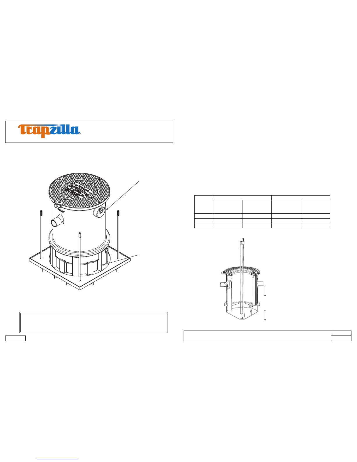
Trapzilla®Grease Interceptor
Installation and Operations Manual
TZ-160, TZ-400, TZ-600 Models
AFE
MNL-TZ 25
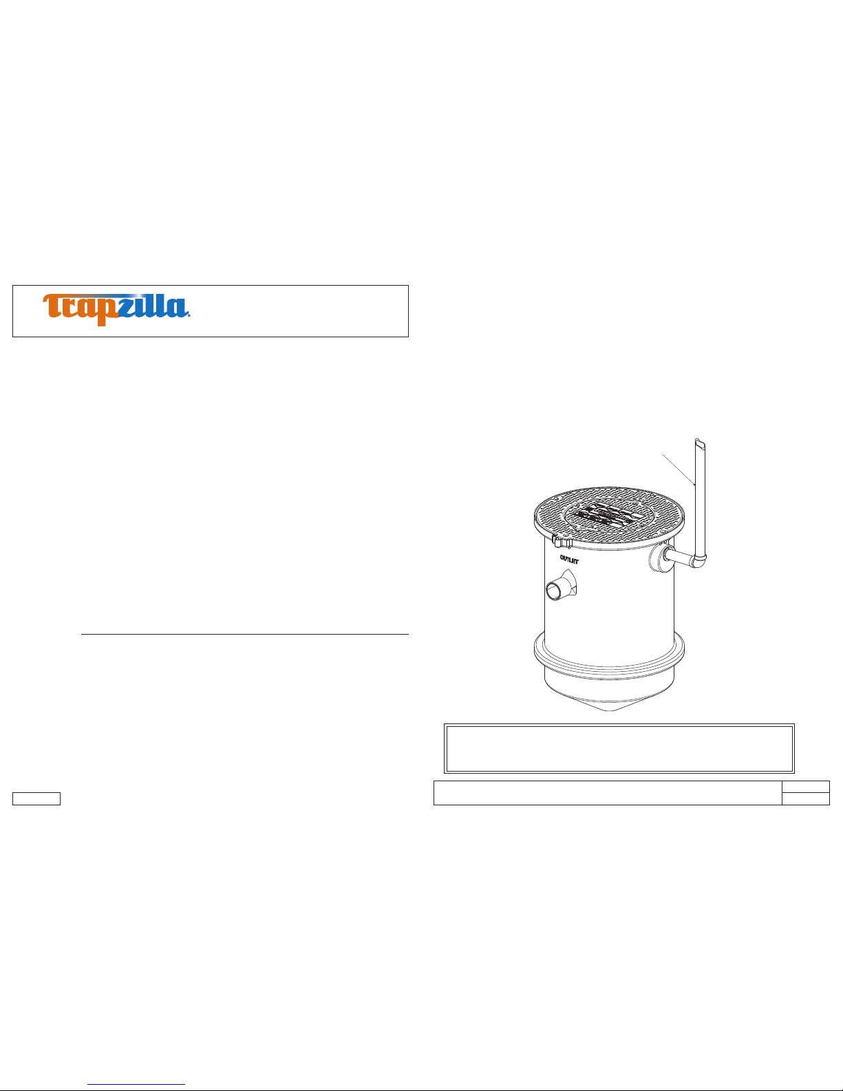
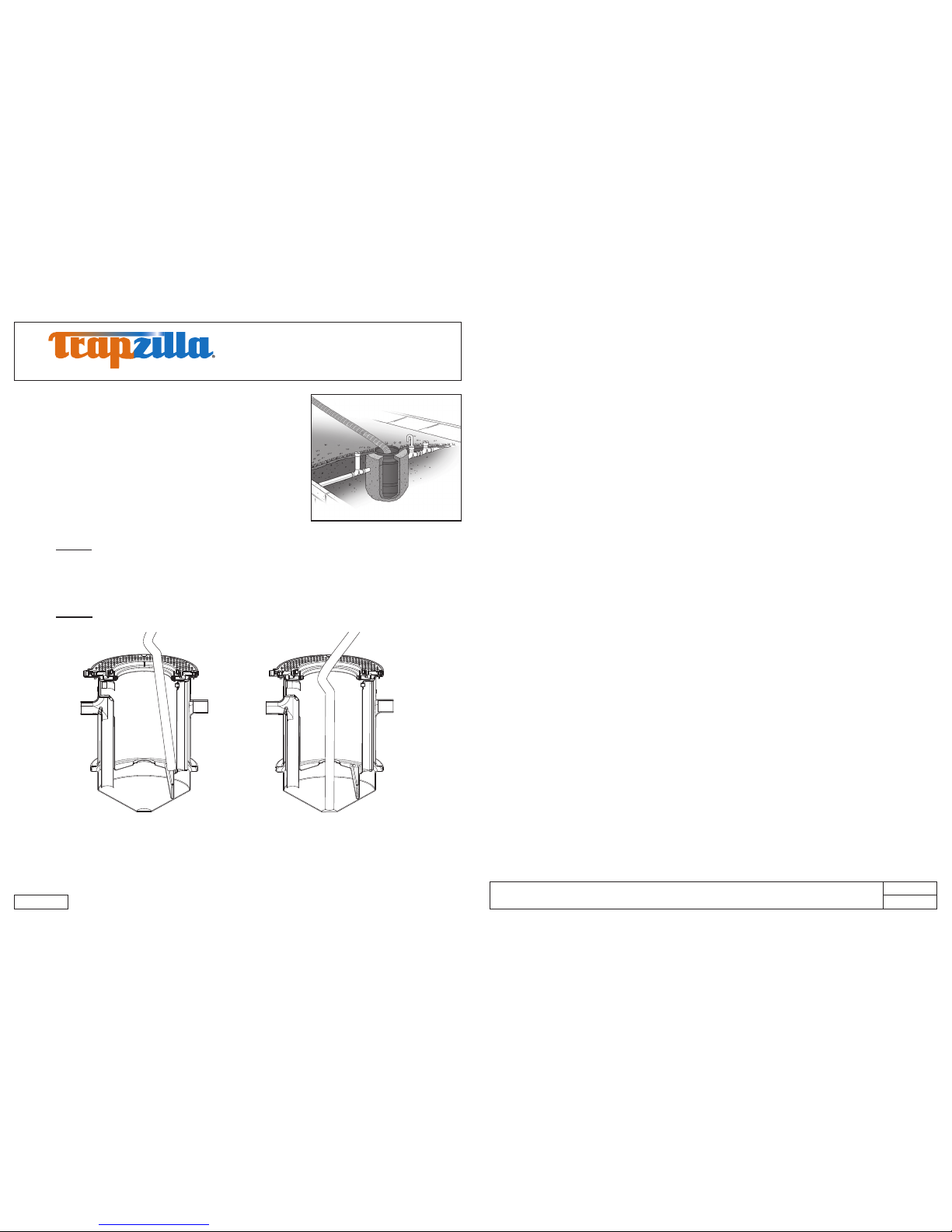
8.0 Unit Maintenance
Periodically, the Trapzilla® unit will need to be serviced which
involves pumping out the accumulated grease & solids. Each
lid has four brass nuts securing the lid. Fully remove the lid to
access the grease. Begin by taking the grease from the top of the
main chamber. Upon reaching the horizontal bafe, you will see
a hole through which you may access the rest of the grease and
the solids. Be sure to lower the hose all the way to the bottom
of the Trapzilla unit so that solids may be entirely removed.
Note:
1. DO NOT use mechanical crust breaking devices to break down any mat that has formed inside
the Trapzilla unit.
2. Remove the four brass nuts from the bolts and fully remove the lid to pump out.
3. It is not necessary to remove adapter lid (ring) to pump out Trapzilla.
4. If necessary, use a water hose with spray nozzle to rinse off inside of unit.
5. DO NOT use grinding augers in maintenance of the Trapzilla unit.
Begin by pumping grease from upper
chamber, until you can see the entire
horizontal bafe.
May be necessary to use water hose to
rinse out parts of upper chamber.
Drop hose into lower chamber through hole
in horizontal bafe, pumping out all liquids
and solids remaining.
Again, it may be necessary to use water
hose to rinse out lower chamber.
9.0 Limited Warranty and Remedy
Thermaco, Inc. warrants to the original user that the equipment manufactured by Thermaco and deliv-
ered with this warranty (the “Product”) shall be free from material defects in workmanship and materials
during the lifetime of the plumbing system in which the Product is initially installed.
Any claim under this warranty must be made in writing to Thermaco at 646 Greensboro Street, Ashe-
boro, NC 27203 promptly after discovery of the defect and the Product must be delivered, prepaid, to
Thermaco, together with proof of purchase and a return authorization number issued by Thermaco. If
Thermaco determines that the Product is defective, Thermaco’s sole obligation, and the purchaser’s
sole and exclusive remedy, is the repair or replacement, at Thermaco’s option, of the defective Product.
This warranty shall not cover any defect or damage resulting directly or indirectly from: (i) failure to
properly install, operate or maintain the Product in accordance with Thermaco’s instructions, including,
without limitation, use in excess of rated ow, installation deeper than manufacturer’s recommendation
or in conjunction with unapproved components, use to remove emulsied fats and oils or use that fails
to comply with applicable laws, regulations or codes; (ii) damage in transit, handling or installation; (iii)
modications, adjustments, or alterations of the Product; (iv) disassembly of components other than as
required for prescribed maintenance; or (v) any other causes not arising out of defects in workmanship
or materials. Thermaco shall not be responsible for damage to Products resulting from ultraviolet light
exposure, vault ooding, sewer line back-up, pumping or lift station failure, ambient water ow, freez-
ing, or other sources of water damage. Costs for any service, adjustment, removal, repair, packing, or
otherwise incurred with respect to the Product prior to submission for warranty are the responsibility of
purchaser.
No distributor, sales representative or other person is authorized to make any warranty statements on
behalf of Thermaco regarding Products other than as provided herein. This statement of warranty su-
persedes any quote, brochure, or other statement or document with respect to warranty of Thermaco
products.
EXCEPT AS EXPRESSLY SET FORTH ABOVE, THERMACO MAKES NO REPRESENTATIONS,
WARRANTIES OR GUARANTEES, EITHER EXPRESSED OR IMPLIED, INCLUDING, WITHOUT
LIMITATION, AS TO MERCHANTABILITY OR FITNESS FOR A PARTICULAR PURPOSE, WHETHER
OR NOT THERMACO HAD KNOWLEDGE OF PURCHASER’S PARTICULAR REQUIREMENTS OR
NEEDS, OR WITH RESPECT TO ODOR GENERATION OR OTHER INCIDENTALS RELATING TO
USE OF THE PRODUCT.
The sole and exclusive remedy with respect to this warranty or any other claim relating to defects or any
other condition or use of Products, however caused, and whether such claim is based upon warranty,
contract, tort, strict liability or any other theory, is LIMITED to the repair or replacement of the Product,
excluding any cost to remove or install the Product or, at Thermaco’s option, repayment of the pur-
chase price. IN NO EVENT SHALL THERMACO BE LIABLE, WHETHER IN CONTRACT, WARRAN-
TY, TORT (INCLUDING NEGLIGENCE), STRICT LIABILITY, INDEMNITY OR ANY OTHER LEGAL
THEORY, FOR INCIDENTAL OR CONSEQUENTIAL DAMAGES. UNDER NO CIRCUMSTANCES
WILL THE AGGREGATE LIABILITY OF THERMACO FOR ANY CAUSE OF ACTION RELATED TO
THE PRODUCT COVERED HEREBY EXCEED THE NET PURCHASE PRICE RECEIVED BY THER-
MACO FOR THE PRODUCT.
Note: Do not Pressure/Hydrostatic test our units.