Travel Vision TVA 65 User manual

USER MANUAL
Travel Vision TVA 65/80 (Premium) ®
Version 2.3 August 2017 (Eutelsat 9 for Hispasat)
All from 2016
www.travel-vision.com

Page
2
Introduction
Congratulations on the purchase of your Travel Vision TVA 65/80 (Premium).
This user manual provides all necessary information on the installation, operation and maintenance of your
system.
De Travel Vision TVA 65/80 (Premium) is designed to receive TV signals from a satellite on a vehicle such as a
camper, caravan, minibus, trucks and buses at park position. With just a push of a button, the Travel Vision TVA
65/80 (Premium) automatically finds the satellite of your choosing.
The system requires a clear view of the satellite to maximize the signal reception. Objects such as tall trees,
bridges and buildings that block this view will cause a loss of signal and the automatic aiming will not fuction.
Heavy rain, cloud, snow or ice may also interfere with the signal reception quality.
WARNINGS AND REMARKS
The contents of this manual are up to date at the time of print. In no way, can TravelVision BV be held liable for
any errors that may occurred while writing this manual.
TravelVision BV reserves the right to implement any modifications it deems necessary during the development of
the products, and to modify or change this installation and user manual and the herein described products without
prior notice.
Travel Vision TVA 65/80 (Premium) ® is a registered trade mark of TravelVision BV.
Please first read this user manual before putting your Travel Vision TVA 65/80 (Premium) ® into operation. Follow
all instructions and carefully observe the directions presented in this manual.
For additional information, we kindly ask you to contact the specialist dealer where you purchased your system.
User manuals and software updates can be found on our website: www.travel-vision.com
© Copyright 2017 TravelVision BV

Page 3
Table of contents
1. Safety instructions and warnings ...................................................................................... 4
1.1 Tips before going on vacation .................................................................................................... 4
2. Packaging Travel Vision TVA 65/80 (PREMIUM) ®.................................................................... 5
2.1 Shipment check list Travel Vision TVA 65/80 (PREMIUM) ® .................................................... 5
2.2 Antenna outdoor unit Travel Vision TVA 65/80 (PREMIUM) ®.................................................. 5
2.3 Parts Travel Vision TVA 65/80 (PREMIUM) ®........................................................................... 6
3. Determine installation position ................................................................................................... 7
3.1 Determine the cable wiring through interior ...............................................................................8
3.2 Installating .................................................................................................................................. 9
4. Function control panel and control box................................................................................... 11
5. LNB and Skew............................................................................................................................. 12
5.1 Single or Twin LNB................................................................................................................... 12
5.2 Skew......................................................................................................................................... 12
5.3 Auto Skew ................................................................................................................................ 12
5.4 Manual skew set for model TVA 65..........................................................................................12
6. Use, search for satellite. ............................................................................................................ 14
7. Select satellite:............................................................................................................................ 15
7.1 Manually selecting of satellite:.................................................................................................. 15
7.2 Automatic switching between the satellites with DiSEqC......................................................... 15
7.3 Specific comments while searching for the satellite.................................................................15
8. Disabling/Parking position.................................................................................................... 15
9. Update...................................................................................................................................... 16
9.1 Frequency update..................................................................................................................... 16
9.2 Firmware update....................................................................................................................... 16
10. Troubleshooting ..................................................................................................................... 18
10.1 No satellite found, ................................................................................................................18
10.2 Satellite found, but no picture:..............................................................................................18
10.3 Satellite found, but not all channels: ....................................................................................18
10.4 The system does nothing. Possible causes / solutions:....................................................... 18
10.5 Should the software update files be opened before putting them on a USB stick?............. 18
10.6 Should the vehicle with system be level? ............................................................................ 18
10.7 The system has found the satellite but is aligned to another object.................................... 18
10.8 Explanation of Error Codes in the control panel................................................................... 19
10.9 Other technical questions..................................................................................................... 19
11. Footprint TVA systems:......................................................................................................... 20
12. Technical Specifications ....................................................................................................... 21
13. Warranty conditions............................................................................................................... 21

Page
4
1. Safety instructions and warnings
Carefully read this user manual before using the device.
Scope of use
Your Travel Vision TVA 65/80 premium ® has been developed to automatically search and find a satellite signal
on a parked vehicle. This device is only intended for use by consumers and outdoors.
For safe use, please observe the following:
Travelvision TVA 65/80 (PREMIUM)
The system is not suitable for operating while the vehicle is in motion. Operating during drive may cause
damage to the vehicle as well as it will be dangerous for life safety.
This product is with retracted
antenna for fixed installation on vehicles with a maximum speed of 130 Km/h.
Antenna dish outdoor unit
The antenna dish outdoor unit which is installed on top of the vehicle, causes a height on the vehicle.
Make sure that this height will not cause any risk while cruising you’re your vehicle. It is very important
that to be aware of this height for safety while crossing a bridge, crossover or wooded road.
Retract the
system during periods of strong wind or storm.
Installing Antenna dish outdoor unit
It is important that the closing direction of the antenna should be towards back of the vehicle. In this
position, the wind effect is at the minimum level during the driving of the vehicle when the antenna is
closed.
During alignment
Make sure not come into physical contact with the dish unit while it is aligning and rotating. Only use the
control module and make sure nothing and nobody enters the turning circle of the system during its
alignment.
Connecting the system
Always first fully connect the system before switching on the power supply. Otherwise you risk receiving
a slight electric shock.
In order to ensure that your Vision system works properly, you must ensure that it is
correctly connected to the ignition of your vehicle
When it is correctly installed, the antenna automatically returns to the park position when the ignition is
switched on and locks itself there. If the system cannot fully retract or cannot retract at all due to a fault,
then it is your responsibility as the driver of the vehicle to check that the antenna is safely and properly
stowed.
The driver of the vehicle must inspect the external unit before driving off to ensure that it
is fully retracted.
Snow and Ice
If the antenna is covered by snow or ice, do not operate the system. That kind of usage may cause
permanent damages to the system.
Maintenance
There are no parts in the device that require servicing by the user. Do not open the cover of the unit. To
open the covers cancels the guarantee of the unit. Refer to authorized technical service.
Do not clean your vehicle with the mounted satellite system in a drive-through car wash or with a high-
pressure cleaner.
1.1 Tips before going on vacation
Check whether your subscription or smart cart is still valid.
Check the correct function of the system.
Check the website www.travel-vision.com or ask your dealer for any software updates.

Page 5
2. Packaging Travel Vision TVA 65/80 (PREMIUM) ®
The Travel Vision TVA 65/80 (PREMIUM) ® is packed in a wooden box, the system is fixed by means of
4 screws.
Before opening the box, check the box may not be deformed and may not have serious and obvious
signs of damage such as cracks or dents resulting from impact.
Attention! Lift the antenna on the base/mounting plate and not on Dish itself.
2.1 Shipment check list Travel Vision TVA 65/80 (PREMIUM) ®
Antenna dish outdoor unit
-complete antenna unit with LNB and mounting plate
-4 m coaxial- and motor controle cable with junction box
Controlbox
Controlepanel with 1.5 mtr cable
Support bracket
2 mtr powercable
5 mtr Motor control cable
5 mtr coaxial cable (2 pc.with Twin LNB TVA 80 (Premium))
Usermanual
2.2 Antenna outdoor unit Travel Vision TVA 65/80 (PREMIUM) ®
Dish
LNB
Mountingplate

Page
6
2.3 Parts Travel Vision TVA 65/80 (PREMIUM) ®
5 m Coaxialcable 5 m Controle cable 1,5 m Coaxialcable
Controlpanel Controlebox Mounting controlbox
Support Bracket Junctionbox
Page 7
3. Determine installation position
By determine the antenna installation position you should check:
•Before installing the system, make sure that the surface is flat, dry and clean, on which the antenna will
be mounted.
•The equipment must only be installed on hard vehicle roofs which are sufficiently strong and inherently
stable.
•Make sure that there are no physical obstacles on the vehicle that prevent watching the satellites and
motion of the dish, when choosing the installation place of the antenna.
•Make sure that the installation base is a rigid surface and it never stretches.
•It is important that the closing direction of the antenna should be towards back of the vehicle. In this
position, the wind effect is at the minimum level during the driving of the vehicle when the antenna is
closed.
Determine the cable wiring towards controlebox.
Depending on the desire there are two different possibilities for wiring:
•Wiring duct from the side
•Cabling Transit through middle bottom
Wiring duct from the side
Cabling Transit through middle bottom

Page
8
3.1 Determine the cable wiring through interior
Determine the cable wiring through interior and position of the control box, advised the control box close
to the TV and receiver.
Electric diagram Travel Vision TVA 65/80 (PREMIUM) ®

Page 9
3.2 Installating
1. Before installing the system, make sure that the place is dry and clean, on which the antenna will be
mounted.
It is important that the closing direction of the antenna should be towards back of the vehicle. In this
position, the wind effect is at the minimum level during the driving of the vehicle when the antenna is
closed.
2. Depending on the requirements; two different motor unit installation method can be used.
a. Fixing with bold; align the dish holes with rivets on the mounting bracket and place the dish
onto the mounting bracket. Screw forepart of the dish to mounting bracket with M6x10 screws.
Use silicon to isolate the tighten screws.
b. Fixing with bonding: Lead up the mounting surface and motor unit base plate according the
adhesive. Fix the motor unit by bonding it to the mounting surface.
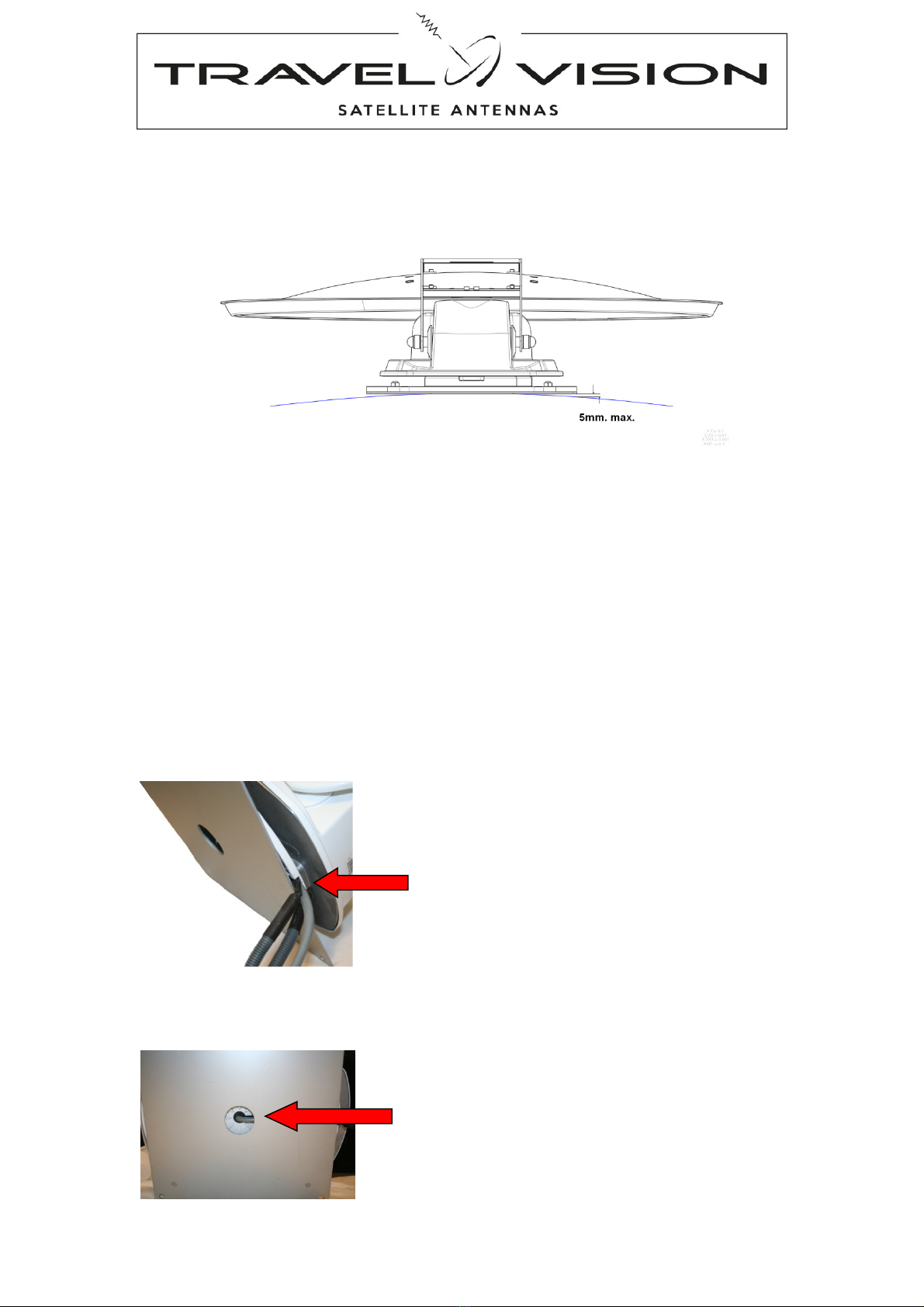
3. Stick the support bracket 50 of 65 cm (depends dish size) from the rear-middle axis of the antenna.
Check this position before confirming the support.
4. Enter the necessary cables through the roof and mount (if desired with mounting cables from the side)
the roof junction box.
a. Mounting hole diameter 18 mm 12-pin connector
b. Mounting hole diameter 13 mm F-Connector
Page
10
5. Run the cables from roof through the interior to the control box
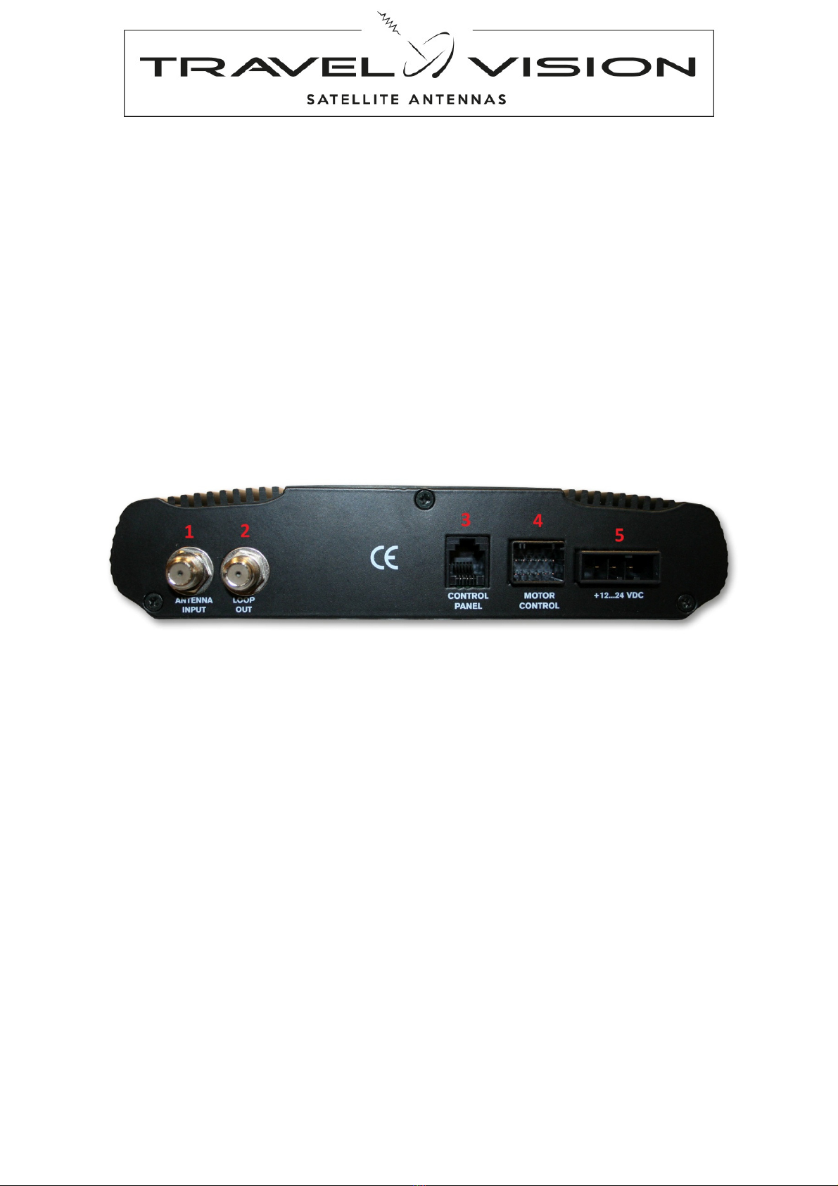
6. Connect the motor control cable to motor control (4) control box
7. Connect the 5-m coaxial cable to antenna Input (1) control box
a. Optional with Twin LNB, connect 2
e
coaxial cable on 2
e
receiver
8. Connect the 1,5-m coaxial cable from Loop Out (2) control box to receiver
9. Connect your TV to receiver as instructed by your receiver/TV manual.
10. Connect Control Panel on (3) control box
11. Connect power cable on (5) control box
12. Connect contact (blue) from power cable on contact of vehicle.
13. Connect power cable to 12 or 24 V DC vehicle. (use for any extension to the power supply 2.5 mm to
4.00 mm cable).
The system is now ready for use. If all cables and connectors are connected, you can turn on the power.
Controlbox Back

Page 11
4. Function control panel and control box
Control box:
Steering The built-in electronics provides as system operator.
Monitoring Display of the system status
Updating updating software.
6. On/Off (Power supply on/off)
7. Power light Red
8. Con light green
9. USB port
Controlbox front
Controlepanel:
Control Giving instructions to the control box e.g. Satellite choice, turn on / off, etc.
Monitoring Selected satellite
10. Up
11. Down
12. Stand-by
Switch on: system search satellite
Switch off: system returns to parking
position and switch off (standby-mode)
13. Display satellite choise
Control panel

Page
12
5. LNB and Skew
5.1 Single or Twin LNB
The centrepiece of the satellite antenna is the LNB, which bundles and processes the satellite signals. Per your
individual needs, it’s available in different variants. For example, if you want to use a second receiver, e.g. in the
sleeper compartment, you need a Twin LNB to connect a second independent receiver.
The TVA 65 with single LNB, suitable for connection of 1 receiver
The TVA 80 (Premium) with a twin LNB, which allows connection of two receivers that can operate independently.
5.2 Skew
For optimal reception at the limits of the reception ranges in South East and West regions, the LNB may have to
be rotated in order to compensate the polarisation deviation (SKEW angle) caused by the earth’s curvature.
5.3 Auto Skew
The TVA 80 (Premium) antenna has Autoskew, the system automatically rotates the LNB to be assured of
optimum signal.
5.4 Manual skew set for model TVA 65
With the TVA 65 the skew should be manual set.
The LNB is provided in a white plastic cover, which can be opened to adjust the skew.
With factory set, the LNB is set to +5. Before searching the satellite, you need to check or the LNB-skew must be
adapted.
Checking Skew
The table below is only a tool, if the current LNB skew setting has more difference as 10 degrees, there is a big
possibility that the system will not align with the satellite, or services from the receiver will be lost (picture will
freeze frame and may disappear).
Check your position in table below.
Astra 1 19'2E Astra 3 23,5E Astra 2 28E Hotbird 13E Eutelsat 9 E Thor 1 W
Scandinavia
0 0 0 -3,5 - 3 - 7
Netherlands,Belgium,Germany +3,5 +7 +10,5 0 -3 -7
UK
/ Ireland
+7 +10,5 +14 +7 +12 +7
France
+7 +10,5 +14 +3,5 +7 -7
Portugal / Spain
+17,5 +17,5 +21 +14 +15 +7
Austria / Croatia / Italy
0 +3,5 +7 -3,5 -5 -14
Tunisia
+3,5 +7 +17,5 0 0 -14
Morocco +24,5 * +31,5 +21 +24 +7
Canary Islands
+28 +35 +38,5 +31,5 +36 +24,5
Greece / Romania
-14 -10,5 +3,5 +7 +16,5 -24,5
Note: This table contains only an average for the skew adjustment
Page 13
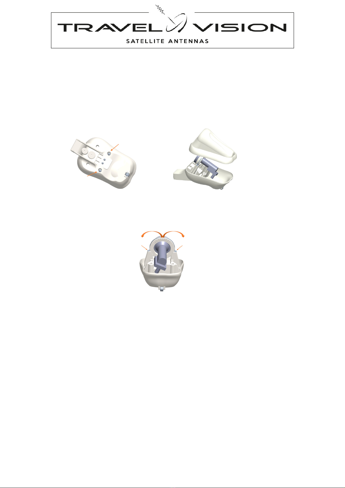
Manual setting skew
The LNB is provided in a white plastic cover, which can be opened to unscrew the two screws on the bottom of
this cover. When the cover is opened, the LNB with a degree distribution becomes visible.
Positive degree Skew LNB is clockwise rotation (Viewing from the LNB into the mirror) negative degree in counter
clockwise direction.
1. Unscrew the two screws at the bottom of the LNB cover and remove the cover.
2. Slightly loosen the two small screws from mounting LNB degree, just to turn the LNB to the correct position
3. Tighten the two small screws from LNB degree and attach the cover with two screws on the bottom

Page
14
6. Use, search for satellite.
Power on:
Switch the control box (button 6.) to On (first time operating).
The red LED (7) of the control box lights up and after a few seconds the blue illumination of the control panel
lights up as well. The red LED (7) on the control box goes out and the system goes into standby mode.
The system is now initiated and ready for use.
Search for satellite:
•Please ensure that the system always has a clear view. In Europe, all satellites are in an approximate
position in the south.
Depending on your system there are 3 possibilities:
1. Standard LNB with TVA 65
2. Autoskew LNB with TVA 80
3. Autoskew LNB with TVA 80 Premium
Standard LNB with TVA 65
Check in section 5.4 the correct LNB setting for the desired satellite. If necessary, set the LNB of your antenna.
Press the standby button (12.) of the control panel. The blue back light on the control panel lights up and the
antenna moves up.
The antenna searches for the last selected satellite, also displayed on the control panel by a slow blinking LED
(13). The elevation (height) also starts at the position that the satellite was previously located.
Once the TVA 65 has located the satellite, it will optimally align with small steps after checking. To indicate that
the satellite has been located the chosen satellite LED (13) flashes quickly.
This process takes about 1 minute. After this optimisation phase, the system is in-line with the satellite.
To indicate that the satellite has been located and aligned, the chosen satellite LED (13) lights continuously.
The signal is now fully passed on to the connected satellite receiver and you can watch TV.
Autoskew LNB with TVA 80
Press the standby button (12.) of the control panel. The blue back light on the control panel lights up and the
antenna moves up. The antenna searches for the last selected satellite, also displayed on the control panel by a
slow blinking LED (13). The elevation (height) also starts at the position that the satellite was previously located.
Once the TVA 80 has located the satellite, it will optimally align with small increments after checking. To indicate
that he satellite has been located the chosen satellite LED (13) flashes quickly.
During the optimisation of the satellite, the system checks the optimum position of the LNB by means of
autoskew.
This process takes about 1.5 minutes. After this optimisation phase, the system is in-line with the satellite. To
indicate that the satellite has been located and aligned the chosen satellite LED (13) lights continuously.
The signal is now fully passed on to the connected satellite receiver and you can watch TV.
Autoskew LNB with TVA 80 Premium
Press the standby button (12.) of the control panel. The blue back light on the control panel lights up and the
antenna moves up. The antenna searches for the last selected satellite, also displayed on the control panel by a
slow blinking LED (13).
By means of the built-in GPS, compass and clinometer the elevation height, location of the satellite and the Skew
settings will be determined and selected.
NB. If the controller on the power button was turned off and has just been turned on, it takes longer before the
GPS location and the position of the satellite will be determined.
Once the Travel Vision TVA 80 PREMIUM has located the desired satellite, it will optimally align with small
increments after checking. To indicate that the satellite has been located, the chosen satellite LED (13) flashes
quickly. This procedure takes about 30 seconds. After this optimisation phase, the system is in-line with the
satellite.To indicate that the satellite has been located and aligned the chosen satellite LED (13) lights
continuously.The signal is now fully passed on to the connected satellite receiver and you can watch TV.

Page 15
7. Select satellite:
At the initial commissioning the system is pre-selected for the Astra 3 satellite. From this point, the
system will display the last selected satellite on the control panel during start-up.
If the system is not in operation press the stand-by button (12.) on the control panel to start the search
process.
There are 2 ways to select the satellite.
1. Manually using the control panel
2. Automatically by means of the connected receiver (All systems from March 2016).
7.1 Manually selecting of satellite:
With the help of the arrow buttons (10 and 11) on the control panel you are able to select the pre-
programmed satellites step by step.
During the search process, you are able to press the buttons and select another satellite.
The system adapts this choice and will search for the desired satellite and align it.
List of preprogramed satellites from which to choose:
7.2 Automatic switching between the satellites with DiSEqC
Depending on the selected channel of your receiver (or TV with built-in receiver) the system searches the
desired satellite.
The TVA system is programmed to automatically align with DiSEqC. If you have a programmed DiSEqC
channel list into your receiver, the satellite dish turns automatically to the right satellite belonging to the
TV channel you have selected. For a TV channel that is broadcast through Astra 2 the antenna aligns to
Astra 2, and for a channel of Astra 1 it aligns to Astra 1 etc. If this function is not desirable and just want
to switch manually with the control panel of the satellite dish, turn off the DiSEqC settings in the menu of
the connected receiver (or TV with built-in receiver).
NB. To use DiSEqC, the receiver must be connected to the loop-out of the control box.
7.3 Specific comments while searching for the satellite
If the system stops running because it has found a satellite with the right features, but during the
checking it appears that this is not the satellite you selected, the system automatically continues
searching for the right satellite.
8. Parking position
Press the standby button (12.) of the control panel.
The blue back light on the control panel lights and the antenna shuts itself down.
To indicate the antenna is retracting, no LED on the control panel (13.) is lit.
After retracting the antenna, the control unit turns itself off to standby mode. You can turn off your
receiver and TV.
NB. If the ignition switch is connected (strictly recommended) then the antenna automatically retracts as
protection after the ignition switch is switched on.
The standby button can be used at any time to turn the system off, even if it is still searching.
Satellite Position Display
Astra 1 19.2 Astra19
Astra 3 23.5 Astra23
Astra 2 28.2 Astra28
Hotbird 13 E Hotbird
Eutelsat 9 E Eutelsat9
Thor 1 W Thor

Page
16
9.
Update
9.1 Frequency update
The Travel Vision TVA searches for satellites based on various preprogrammed frequencies. These
frequencies have been carefully selected by Travel Vision BV, but they are subject to change. When
these frequencies change, Travel Vision BV will release new software so that the system can use the
new frequencies. This software is freely available for download at the website www.travel-vision.com and
at your local dealer
Download the software for your type TVA Travel Vision system from the website.
1. Change the extension (for example mtHWInfo.bin) from downloaded fileto .txt (mtHWInfo.txt)
o
Press right mouse-button on downloaded file en select “change name”
o
Change the extension from .bin or mht to .txt
2. Store the file on a USB Flash drive (min 1 Mb)
3. Power off the antenna with control box, button (6).
4. Insert the USB Flash drive in the slot (9) of control box
5. Power On the antenna with control box, button (6).
6. Red LED (7) and green LED (8) flashes 4- 5 times and then continuously.
7. Wait until both LEDs are off.
8. Switch the Power button (6) from control box off and on again.
9. Control Box will reboot with the new update, you can remove the stick.
10. The system is ready for use.
9.2 Firmware update
If there are significant changes for the general operation of the system, the firmware can be updated.
Travel Vision BV will release this firmware and its freely available for download at the website
www.travel-vision.com and at your local dealer
1. Download the Firmware software for your type Travel Vision TVA 65/80 (PREMIUM) system from the
website.
2. Store the file on a USB Flash drive (min 1 Mb)
format the USB flash drive to FAT32.
3. Power off the antenna with control box, button (6).
4. Insert the USB Flash drive in the slot (9) of control box
5. Press simultaneously button Up (10) and Down(11) from control panel, and hold.
6. Power On the antenna with control box, button (6). (still up and down pressed)
7. Green LED (8) controlebox flashes 9-10 times (after first flash you can release the Up and Down button)
and then continuously. If the LED not flashes, you may have already installed the same software, check
the firmware version. (See 9.3)
8. Switch the Power button (6) from control box off and on again.
9. The Control Box will reboot with the new update, you can remove the stick.
10. Install always after this procedure, always the frequency file (see 9.1) for your system!
11. The system is ready for use.

Page 17
9.3 check Firmware version
Checking the currently installed firmware is possible by making a log file from the control box and checking on a
PC.
Logfile TVA controle box:
Power off the antenna with control box, button (6)
Insert an empty USB flash drive in slot (9) of control box
Power On the antenna with control box, button (6)
RED led (7) turns on and green led (8) flashes 4 times and then continuously.
Then both LEDs go out.
Remove the USB Flash drive
On the USB flash drive is stored a logfile: motoSat.log
This text file can be open with a Word processor from your PC
Remark: text below is an example and may vary by type of system.
S1|f: *****,sr:*****,p:H,el:***,az:***,epos:****,sk:**,
S2|f: *****,sr:*****,p:H,el:***,az:***,epos:****,sk:**,
S3|f: *****,sr:*****,p:H,el:***,az:***,epos:****,sk:**,
S4|f: *****,sr:*****,p:H,el:***,az:***,epos:****,sk:**,
S5|f: *****,sr:*****,p:H,el:***,az:***,epos:****,sk:**,
S6|f: *****,sr:*****,p:H,el:***,az:***,epos:****,sk:**,
S7|f: *****,sr:*****,p:H,el:***,az:***,epos:****,sk:**,
S8|f: *****,sr:*****,p:H,el:***,az:***,epos:****,sk:**,
Etc
Etc
etc
MTV5R8_2016/5/27:16 V1_R3_24.11.2014
The last sentence indicates the firmware version, the RED marked numbers is the version number of the
firmware. In this case 5.8.
The * stars are numbers depending type of TVA system.

Page
18
10. Troubleshooting
10.1 No satellite found,
1) Check whether there are any obstructions on the south which blocks the free satellite view.
2) Check the LNB skew setting (See section 5.4) only with TVA 65
3) You are possibly outside the broadcast area of the desired satellite. Check footprint in section 11.
If you are sure that the above does not apply:
4) Check if the latest Travel Vision TVA ® software version has been installed for any possibly changed
satellite frequencies. See www.travel-vision.com or consult your dealer.
5) Check the LNB, coaxial cables and connectors from Outdoor antenna and antenna input (1) on controller
10.2 Satellite found, but no picture:
Check the coaxial cable between controller (loop out) and your satellite receiver
Check the connection cables between your satellite receiver and your television.
Switch the receiver and the television off and back on.
Check if the latest software version and channel list has been installed in your receiver
10.3 Satellite found, but not all TV channels:
Check if the latest software version and channel list has been installed in your receiver
Check whether your subscription or smart cart is still valid.
Check the LNB skew setting (See section 5.4) with TVA 65
10.4 The system does nothing. Possible causes / solutions:
Is the power button on the control box switched to on?
Red LED (7) on control box?
No, Check powersupply
Check fuses
Check powercable on controlebox
Yes, Check vehicle contact
Check cable control panel
Check cables and battery voltage
10.5 Should the software update files be opened before putting them on a USB stick?
No, You only need to copy (right mouse button to copy) and paste (right click paste) on an empty USB
flash drive. Due to installed anti-virus programs on your PC, it could be possible that you cannot copy the
files directly from your email program. In this case you can create an intermediate step, first copy the
files to your desktop and then copy it to the USB flash drive.
10.6 Should the vehicle with system be level?
With TVA 65-80:
The system has not to be fully level to find the satellite. However, with more level, the satellite is faster
found. Also, it works in favour of the indicated LNB skew position.
With TVA 80 Premium:
No, the built-in clinometer calculates the correct angle for elevation and LNB skew
10.7 The system has found the satellite but is aligned to another object.
The system may align to a reflective surface like the side of the camper van/caravan, due to reflection of
the satellite signal. The satellite signal is sufficient to receive the satellite but is too weak to allow viewing
some (or all) TV channels.
Move the vehicle with antenna and then realign it, or block signal between the dish and the reflective
surface while the search process is in progress.

Page 19
10.8 Explanation of Error Codes in the control panel
From firmware version 7.2 January 2017, also error message codes are displayed with the help of
the control panel
A-Fault scenario
1-
Fault Elevation (vertical movement)
Controlpanel : Alarm sounds, LED3+4.
Cause : Mechanical obstacle detected during movement
Action : Check whether there are any obstacles to the antenna and remove them.
And press Standby button to try again .
2- Fault Azimuth (horizontal motion) during rotation to the park position
Controlepanel : Alarm sounds, LED 1+2+4.
Cause : Mechanical obstacle detected during folding,
Action : Check whether there are any obstacles to the antenna and remove them.
And press Standby button to try again .
B- Explanation of LED error codes in the control panel
1- Elevation encoder failure during opening: LED1
2- Elevation encoder failure during retract: LED2
3- Antenna not reached within the max. time required Azimuth limits: LED1 + LED2
4- During the search, the azimuth of 0 ° detection switch is not found: LED3
5- During the search, the switch azimuth of 360 ° detection is not found: LED1 + LED3
6- During the search, as elevation of 0 ° detection switch is not found: LED2 + LED3
7- During the search, the elevation switch 360 ° detection is not found or the
motor cable is faulty: LED1 + LED3 + LED4
8- LNB or coaxial cable is not connected or defective: LED4
9- TVA 80 Premium antenna, sensor board or GPS sensor is not connected or defective: LED1 + LED4
10- Azimuth motor encoder failure: LED2 + LED4
11- Azimuth overcurrent protection: LED1 + LED2 + LED4
12- Elevation overcurrent protection: LED3 + LED4
Remark: When the ignition switch (blue cable) is activated the antenna retract and gives
3 x alarm sounds from control panel
When the ignition is activated, and the Standby button is pressed, the antenna remains closed,
the control panel sounds 3 x alarm.
10.9 Other technical questions.
If your question is not listed here, you can also send an email to [email protected]
We will answer your question as soon as possible.
It is important that your question also indicates what type of system and control box is installed:
System: Controlebox:
TVA 65 MTC-3710 (front controlbox)
TVA 80 MTC-3811 (front controlbox)
TVA 80 MTC-3812 (front controlbox)
TVA 80 Premium MTC-5812 (front controlbox)

Page
20
11. Foorprint TVA systems:
This manual suits for next models
3
Table of contents
Other Travel Vision Antenna manuals


