Traxon e cue VMC User guide

Video Micro Converter
Setup Manual

Published by
Traxon Technologies Europe GmbH
Karl Schurz-Strasse 38
Paderborn, Germany
An OSRAM Business
Video Micro Converter FW version 2.x
System Manual – Edition 04.12.2012
©2012, Traxon Technologies Europe GmbH
All rights reserved
Comments and corrections:
For a most recent version of this manual please visit:
http://www.ecue.com/download

Table of Contents
English ......................................................................7
Safety instructions .................................................................................... 8
About the Video Micro Converter ............................................................. 9
Highlights............................................................................................. 9
VMC versions .................................................................................... 10
Delivery content and accessories ....................................................... 10
Optional accessories .........................................................................10
Inspect the delivery content ............................................................... 10
Connectors ............................................................................................. 11
Power supply .....................................................................................11
e:net .................................................................................................. 12
DVI .................................................................................................... 12
DVI cable lengths ............................................................................... 12
DMX/e:pix .......................................................................................... 12
Pin assignment .................................................................................. 13
General ................................................................................................... 13
Network configuration ........................................................................ 13
Connecting more than one VMC ........................................................ 13
Setting the IP address using Patchelor ............................................... 14
Make sure that other e:cue applications are closed. ........................... 14
Identifying VMCs in the network ......................................................... 14
Settings overview ............................................................................... 14
Operation elements ................................................................................ 18
The VMC button ................................................................................ 18
Status LED ........................................................................................ 18
Status display .................................................................................... 18
System configuration .............................................................................20
Basics ...............................................................................................20
Video settings ....................................................................................21
Patching ............................................................................................22
Matrix testing ..................................................................................... 23

Refresh rate and configuration size ....................................................23
Daisy-chaining VMCs ............................................................................. 24
VMC chaining example ......................................................................25
VMC System Example with DVI Splitter .............................................. 26
LED matrix default picture .................................................................. 27
Video content and playback............................................................... 27
Common pitfalls ................................................................................. 28
Firmware update ....................................................................................29
Technical data ........................................................................................ 30
Trouble shooting ....................................................................................31
Deutsch ..................................................................33
Sicherheitshinweise ................................................................................ 34
Geräteübersicht ...................................................................................... 35
Der Video Micro Converter ................................................................. 35
Highlights........................................................................................... 35
VMC-Versionen .................................................................................. 36
Lieferumfang und Zubehör ..................................................................... 36
Optionales Zubehör ........................................................................... 36
Packungsinhalt .................................................................................. 36
VMC-Anschlüsse .................................................................................... 37
Netzteil .............................................................................................. 37
e:net .................................................................................................. 38
DVI .................................................................................................... 38
DVI-Kabellängen ................................................................................ 38
DMX/e:pix .......................................................................................... 38
Anschlussbelegung ............................................................................ 39
Geräte-Konfiguration .............................................................................. 39
Netzwerk-Konfiguration ..................................................................... 39
Anschluss mehrerer VMCs ................................................................. 39
IP-Adresse mit dem Patchelor setzen ................................................ 40

5
Setup Manual - Video Micro Converter
VMCs im Netzwerk identifizieren ........................................................ 40
Übersicht der Einstellungen ...............................................................40
Bedienelemente ...................................................................................... 44
Der VMC-Taster ................................................................................. 44
Status-LED ........................................................................................ 44
Status-Anzeige .................................................................................. 44
System-Konfiguration ............................................................................. 46
Grundlagen ........................................................................................ 46
Video-Einstellungen ........................................................................... 47
Patchen ............................................................................................. 48
Test der Matrix ................................................................................... 49
Wiederholrate und Konfigurationgröße ............................................... 49
Verketten von VMCs ............................................................................... 50
Beispiel VMC-Serienschaltung ........................................................... 51
Beispiel VMC-System mit DVI-Splitter ................................................ 52
LED-Matrix Standardbild .................................................................... 53
Video-Inhalt und -Wiedergabe ...........................................................53
Mögliche Fehlerquellen ...................................................................... 54
Firmware-Update ...................................................................................55
Technische Daten ................................................................................... 57
Fehlerbehebung .....................................................................................58
Appendix/Anhang ...................................................61
Dimensions/Abmessungen..................................................................... 62

6
Setup Manual - Video Micro Converter

7
Setup Manual - Video Micro Converter
English
A high resolution version is available from our website
8
Setup Manual - Video Micro Converter
Safety instructions
i
Only use the device in compliance with the environmental conditions
specified and watch the technical characteristics. Otherwise the unit
may be damaged or malfunction will happen.
i
Only use original e:cue accessories to power VMC. Other power sup-
plies can damage the unit.
i
VMC DVI ports must not be hot plugged! In larger matrix systems with
multiple VMC and many fixtures, voltage potential differences may oc-
cure and damage the VMC. Always turn off fixture supplies and VMC
before connecting or disconnecting any VMC.
i
To prevent the device from overheating, only operate it in well-ventilat-
ed environment. Ventilation may not be obstructed. Do not install next
to heat emitting sources or in a place subject to direct sunlight.
Device components inside the system can reach high temperatures!
To avoid burns, allow the unit to cool for at least 20 minutes before
unmount or repair.
i
Installation and maintenance of this product must be performed by
individuals who are knowledgeable about the procedures, precautions
and hazards associated with the product.
i
This description relates to firmware version 2.x, please contact Traxon
Technologies for documentation on version 1.x. Do not mix VMCs
with firmware versions 1.x and 2.x in one installation!
i
VMC with firmware version 2.x can only be configured with e:cue
Patchelor 5.5 or higher!

9
Setup Manual - Video Micro Converter
About the Video Micro Converter
Video Micro Converter (VMC) is a compact device used to convert a DVI signal to
DMX or e:pix for LED control of large media screens. Specially designed to easily
output video content on large LED media installations by grabbing up to 4096 pixels
per VMC.
Multiple VMCs can be daisy chained together to convert the entire DVI source to
control installations requiring more than 4096 pixels. The VMC features very flex-
ible pixel mapping capabilities for demanding LED installations ranging from few
hundred to one million pixels.
e:pix is a protocol based on DMX, developed by Traxon Technologies, for an im-
proved communication between the VMC and TRAXON e:pix-ready LED products.
Highlights
• DVI to DMX/e:pix converter, DVI input resolutions up to 1920 x1080 pixels =
1080p
• Ethernet configuration and patching with e:cue Patchelor
• Grabs and converts up to 4096 RGB pixel per VMC
• Extremely flexible pixel mapping capabilities, internal active DVI signal booster
• Configurable RGB mapping for DMX channels
• Daisy chain up to 8 VMC for up to 32.000 pixel matrixes, with DVI splitter and
multiple VMC chains for up to 1 Million pixel
• Eight DMX or e:pix outputs (user configurable), user selectable DMX/e:pix output
refresh rate
• User selectable DMX/e:pix output channel count
• User selectable default matrix picture on video loss

10
Setup Manual - Video Micro Converter
VMC versions
There are two different VMC versions available. Please note that following descrip-
tion always references both output protocols, but depending on the purchased unit
the actual device might only output DMX.
Version Item No.
VMC DMX and e:pix IN.VC.0000001
VMC DMX DMX IN.VC.0000002
Delivery content and accessories
• Video Micro Converter (DMX or e:pix Version)
• VMC power supply AC.PS.0123000
• Ethernet Patch Cable 1 m AC.NW.0000001
• LAS Installation CD SW.LA.0000000
• HDMI to DVI Adapter AC.DV.1800007
• DVI Cable 2 m dual link AC.IN.0000020
• Setup Manual English/German
Optional accessories
• VMC Garage for 19” rack mounting 160194
(houses three VMC and power supply)
• DVI to HDMI Adapter
• RJ-45 to XLR Adapter – XLR-5-Pin fem. AC.BU.0000010
Inspect the delivery content
Unpack the VMC and inspect all parts for completeness. Keep the packaging for
use in case of further transport. If there is apparent damage to the device or parts
are missing from the delivery scope, please contact Traxon Technologies service.
11
Setup Manual - Video Micro Converter
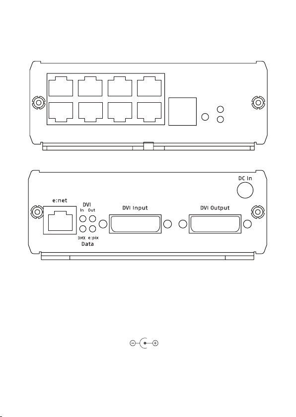
Connectors
1 2 3 4
5 6 7 8 8
DMX/e:pix outputs
Status
Power
DVI
Power supply
The Video Micro Converter is powered by an external AC/DC power supply. Only
use original e:cue accessory to power VMCs.
VMC Input Voltage: 12 V DC
Power Consumption: 5 W
Connector polarity:

12
Setup Manual - Video Micro Converter
e:net
e:cue’s e:net is an Ethernet based protocol. Therefore use standard CAT5 (RJ-45)
network cabling for e:net connections. Standard ethernet infrastructure equipment
like hubs or switches are used for e:net interconnection in case of having multiple
VMCs. Depending on your networking adapter your PC might require a cross link
CAT5 cable for direct connections to a VMC.
i
Note that e:net devices should only be used in isolated network seg-
ments. Devices might not operate properly when using e.g. internet or
video/audio streaming within network simultaneously.
DVI
VMC supports single link DVI-D signals for resolutions up to 1920 x 1080 px =
1080p. HDMI video sources may also be connected and will either require a special
HDMI to DVI cable or use of an HDMI to DVI adapter (adapter is included in the
VMC accessories).
On its DVI output, VMC acts like an active video booster or repeater. Output video
signals again match the DVI-D single link standard. Users may connect another
VMC, a control monitor to VMC or may decide to leave the output unconnected.
Again, please make use of DVI to HDMI adapters if you require connecting to moni-
tors, beamer or devices only supporting the HDMI standard.
DVI cable lengths
The maximum length of the DVI cable for resolutions up to 720p is 10 meters, for
1080p only 2 meters.
i
When connected to the VMC, control monitor on the output must be
compatible with the video source resolution and refresh rate.
DMX/e:pix
Eight RJ-45 outputs are available for connecting DMX/e:pix compatible fixtures with
a total of up to 4096 individual pixels. Output data protocol is user selectable and
can configured as DMX or e:pix in the e:cue Patchelor. Output interface can be set
to Traxon/e:cue or ESTA.

13
Setup Manual - Video Micro Converter
Pin assignment
DMX1–
DMX1+
GND
J1
RJ45-2X4
1
2
3
4
5
6
7
8
Pin Traxon e:cue ESTA
1 DMX- DMX+
2 DMX+ DMX-
3 GND GND
4 n.c. n.c.
5 n.c. n.c.
6 n.c. n.c.
7 GND GND
8 GND GND
General
All settings on the VMC are configured remotely using e:cue Patchelor on a network
enabled computer. Patchelor can be installed from the e:cue Lighting Application
Suite installation CD. Patchelor is also available as a free download from www.ecue.
de.
Network configuration
Factory setting of the IP address of a VMC is: 192.168.123.1
Connecting more than one VMC
In case of having several VMC they need to be configured one at a time, please
do not connect all of them to the network immediately. This is due to the fact that
the devices all come with the same IP address as factory default. If all VMCs are
connected simultaneously an IP address conflict will occur and configuration is not
possible. Instead, connect the VMCs one at a time. Connect the first VMC and as-
sign a new IP address to the device (e. g. 192.168.123.11).

14
Setup Manual - Video Micro Converter
Setting the IP address using Patchelor
Make sure that other e:cue applications are closed.
• Start e:cue Patchelor by double clicking the Windows desktop icon or by select-
ing Patchelor from the Windows Start menu.
• Any VMC devices which are connected to the network should appear in the
device manager.
If devices do not show up, check your computer’s IP address and netmask set-
tings. Please also make sure your firewall does not prevent communication between
computer and VMC.
In case of multiple network adapters, please use the correct adapter in the Patch-
elor options dialog.
• Highlight the list entry in device manager, right click and select Congure from
context menu.
• Enter IP address and netmask settings for this VMC
• Repeat steps 4 to 5 until all devices have received an individual IP address.
Identifying VMCs in the network
There are two methods available to identify VMCs in the network:
• Shortly press the VMC button and the Patchelor device manager will highlight
selected unit.
• Activate checkbox in front of the VMC in the Patchelor device manager.
Settings overview
Highlight VMC in device manager, right click and select Congure from context
menu to change device settings. Please note that device status information is not
editable and therefore greyed out.

15
Setup Manual - Video Micro Converter
i
For configuring the VMC the unit must be deselected in the Device
Manager of the Patchelor. Unset the checkmark before the unit in the
lower window.
16
Setup Manual - Video Micro Converter
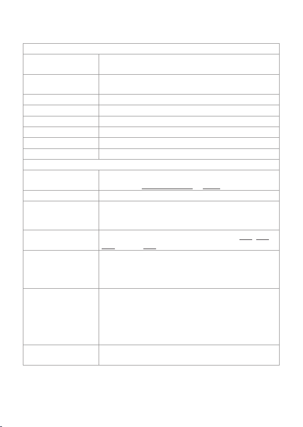
Device Basics
Device Name Device name: individual device names may ease identifi-
cation in larger systems.
IP Address Sets devices IP Address for VMC. Factory default is
192.168.123.1.
Subnet Mask Select network subnet for VMC.
MAC Address MAC Address of the device.
Version
Hardware Build Version Hardware build version, readonly.
Software Build Version Software build version, readonly.
FPGA Build Version FPGA build version, readonly.
Output Settings
Socket Setup For DMX outputs.
Select either Traxon e:cue or ESTA
Output Protocol Select DMX or e:pix (only VMC e:pix).
Output Intensity Sets the output intensity (0 ... 100%). Can be used to
reduce brightness in dark surroundings without modifying
the source video.
Color Mapping Select various channel color mappings, e. g. RGB, RBG,
GBR, default: RGB
Refresh Sets the e:pix refresh rate divider (1 ... 255). Divider will
reduce e:pix output refresh rate based on the incoming
DVI signal. (i.e. set to 1 to equal DVI video refresh rate, set
to 2 for half DVI refresh rate and so forth).
e:pix Channels per
Output
Sets the number of e:pix channels per output. (1 - 2048).
Please note that you might not be able to achieve a
maximum of 2048 channels when using refresh rates
above 40Hz. Either adjust refresh setting to “2” or use
less output channels for refresh rates up to 40Hz (only
VMC e:pix).
e:pix Break Time Set the length of the break time in e:pix protocol (only
VMC e:pix).

17
Setup Manual - Video Micro Converter
DMX Channels per
Output
Sets the number of DMX channels per output. (1 ... 512).
Please note that you might not be able to achieve a maxi-
mum of 512 DMX channels when using refresh rates near
40Hz. Either adjust refresh setting to 2 or use less output
channels for refresh rates up to 40Hz.
DMX Break Time Sets the length of the break time in DMX protocol.
MAB [us] Sets the mark after break time for the DMX protocol.
Add Stopbits Allows insertion of additional stopbits in the DMX
protocol.
Startup Delay [s] Sets a startup delay after power-up. This allows a wait-
time for the DVI source to hide boot screens etc.
DVI settings
Mapped Pixels Status information. Shows the number of pixels that VMC
is patched to and currently converting to DMX/e:pix.
Source Resolution Shows the resolution of the DVI source in pixels and Hz
as refresh rate.
DVI Group Master Indicates whether VMC is first device in a DVI chain. First
unit defines DMX/e:pix output refresh rate and acts as
synchronization master for all following devices. Please
refer to chapter “Daisy Chaining VMC” for details.
Grid Enables marking of grabbed video areas on VMC output.
Can be used during installation or system setup to
align video to grabbing area. The grid can be disabled
afterwards.
Grid Color Set colour for grid. Useful in multiple VMC installations to
quickly identify grabbing areas of individual units, trans-
parent means half-transparent.
On Signal Loss Show user-defined picture or hold last video frame.
Group ID Group ID, define up to 255 independent VMC groups that
are connected to same network.

18
Setup Manual - Video Micro Converter
Operation elements
The VMC button
Button press Action Display
Feedback
short Used to identify VMC in e:cue Patchelor n/a
2 Sec. Store default LED matrix picture
(i.e. company logo or black screen)
“S”
4 Sec. Reset Network Settings
Reset VMC network settings to factory defaults.
“I”
long Exit
Return to normal operation without action
“E”
Status LED
LED Position Description
Power Front Power indicator. Blinking during device bootup,
permanently lid on fully operational unit.
DVI Front Device is converting video to DMX/e:pix, lid when
DVI input signal is valid, a valid patchfile is loaded
and device is in grabbing mode.
DVI In Front Indicates presence of video signal on DVI input.
DVI Out Back Indicates presence of DVI monitor on DVI output.
DMX Back Indicates DMX output mode.
e:pix Back Indicates e:pix output mode.
Status display
Display Description
L o A d Device is in bootloader mode. Message temporarily occurs dur-
ing firmware upgrade. Please upload firmware again if unit stays
in bootloader mode (i.e. failed upgrade)
5 4 3 2 1 C Indicates VMC boot process

19
Setup Manual - Video Micro Converter
static “O” VMC in offline mode. Device is grabbing and converting video.
rotating “O” VMC is in online mode. Device is currently used by Patchelor for
configuration, firmware upgrade or testing purposes.
D D C DDC information update completed. Message occurs on DDC
EDID upgrade. Message disappears on short button press.
F P Device configuration failed. Please contact Traxon Technologies
if device is not recoverable with firmware upload.
S E r Invalid MAC Address. Please contact Traxon Technologies.

20
Setup Manual - Video Micro Converter
System configuration
Basics
To understand the operating configuration of the VMC it is necessary to remember,
that the VMC grabs a defined number of pixels from the incoming video signal,
converts it to DMX/e:pix data and sends it to pixels in the fixture configuration. The
VMC always performs a pixel to pixel conversion, it cannot scale or resize video
content. Only those pixels defined and taken from the video signal in the fixture sec-
tion are mapped, all others are ignored.
Video area =
size of video
content
Pixels taken
from the
input video
signal
DVI
DMX
So, before beginning a project, define the detailed prerequisites for the conversation
and follow these steps:
• What must be the size of the video content? If the video content has to be
resized use a reliable tool or ask the creator of the video to resize the video.
• Use Patchelor to setup the VMCs and the fixtures.
• Define the video area.
• Define the fixture configuration and where the pixels of the fixtures are located in
the video area.
Be aware of these conditions before starting.
This manual suits for next models
3
Table of contents
Languages:


