gefran SIEIDrive EXP-F2E User manual

...... Instruction manual
SIEIDrive
Digital Encoder Input Expansion
and Encoder repeater
EXP-F2E

———— Digital Encoder Input Expansion and Encoder Repeater ————
2
Vi ringraziamo per avere scelto questo prodotto Gefran.
qualsiasi informazione che possa aiutarci a migliorare questo
manuale.
Prima dell’utilizzo del prodotto, leggere attentamente il capitolo
relativo alle istruzioni di sicurezza.
Durante il suo periodo di funzionamento conservate il manuale in un
luogo sicuro e a disposizione del personale tecnico.
Gefran spa si riserva la facoltà di apportare modiche e varianti a
prodotti, dati, dimensioni, in qualsiasi momento senza obbligo di
preavviso.
I dati indicati servono unicamente alla descrizione del prodotto e non
devono essere intesi come proprietà assicurate nel senso legale.
Tutti i diritti riservati.
Thank you for choosing this Gefran product.
We will be glad to receive any possible information which could
help us improve this manual. The e-mail address is the following:
Before using the product, read the safety instruction section carefully.
Keep the manual in a safe place and available to engineering and
installation personnel during the product functioning period.
Gefran spa has the right to modify products, data and dimensions
without notice.
The data can only be used for the product description and they can
not be understood as legally stated properties.
All rights reserved

3
EXP-F2E
Sommario / Table of contents
1. Introduzione/ Introduction ................................................................. 4
3. Connessione encoder / Encoder connector...................................... 7
3.1 Connessione ingresso encoder / Encoder input ............................................... 7
3.2 Connessione ripetizione encoder / Encoder repeater connector ..................... 8
3.2.1 Divisore ripetizione encoder / divider for encoder repeater .............9
4. Leds.................................................................................................. 10
5. Jumpers ........................................................................................... 10
6. Caratteristiche tecniche / Technical data........................................ 11
Dimensioni e peso / Dimensions and weight........................................................... 11
Caratteristiche generali / General data ................................................................... 11
Interfaccia ingresso encoder................................................................................... 11
Ripetizione encoder ................................................................................................ 12
Encoder interface.................................................................................................... 12
Encoder repeater .................................................................................................... 13
Temperatura............................................................................................................ 13
Temperature ........................................................................................................... 13
7. Accessori / Accessories.................................................................. 14
8. Sezione massima cavi / Maximum wire sizes................................. 14
9. Esempio di utilizzo / Example of application ................................... 15
Tach Follower ......................................................................................................... 15

———— Digital Encoder Input Expansion and Encoder Repeater ————
4
1. Introduzione/ Introduction
La EXP-F2E è una scheda di espansione per un ingresso encoder optoisolato e in grado
di fornire la ripetizione dei dati encoder per i drive della serie AVy.
E’ possibile montare una sola scheda di I/O per Drive.
La scheda è composta da:
- 1 ingresso in frequenza optoisolato per encoder composto da:
- ingresso canale A / A negato selezionabile ad una tensione di +5V oppure
15...24V (150kHz max)
- ingresso canale B / B negato selezionabile aa una tensione di +5V oppure
15...24V (150kHz max)
- ingresso canale C / C negato selezionabile ad una tensione di +5V oppure
15...24V (150kHz max)
- ingresso camma di zero (QC+ / QC- negato) 15...30V
Se è utilizzato un encoder digitale con tensione di 15V/24V di tipo complementare (A,
Anot, B, Bnot), è disponibile il segnale di mancanza encoder.
- 1 uscita in frequenza optoisolata ripetizione encoder digitale standard TTL (5V)
oppure HTL (15...24V) composta da:
- uscita canale A e A negato 150kHz max
- uscita canale B e B negato 150kHz max
- uscita canale C e C negato 150kHz max
Inoltre la ripetizione encoder ha la funzione di divisore della frequenza di uscita selezio-
nabile tra /1, /2, /4, /8.
The EXP-F2E card is an AVy drive option used to add a second optocoupled encoder
input and an encoder repeater to the drive. It is possible to use only one I/O expansion
card per Drive.
This option card features:
- 1 optocoupled digital encoder input
- A / A not +5V or 15V - 24V selectable (150kHz max)
- B / B not +5V or 15V - 24V selectable (150kHz max)
- C / C not +5V or 15V - 24V selectable (150kHz max)
- Encoderqualierinput(QC+/QC-)15VDCupto24VDC
Encoder loss detection is available only when a differential encoder is used with a 15V
– 24VDC power supply
- 1 optocoupled encoder data repeater TTL (@5V) and HTL (@15 to 24V)
- A / A not +5V and 15V - 24V (150kHz max)

5
EXP-F2E
- B / B not +5V and 15V - 24V (150kHz max)
- C / C not +5V and 15V - 24V (150kHz max)
- Encoder qualier(home position signal) input (QC+ / QC not) 15VDC up to
24VDC
Encoder repeater has frequency divider functionality selectable between 1, 2, 4, 8 times
using hardware jumpers.
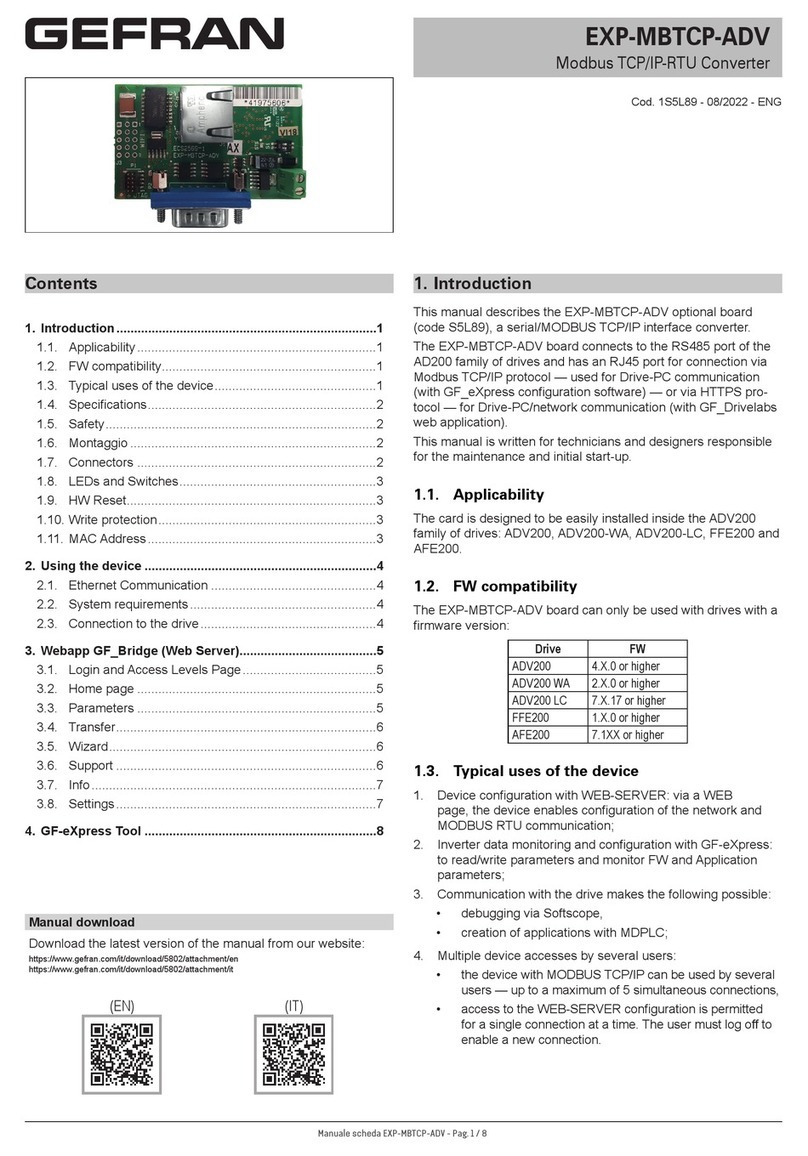
Vista frontale / Front side
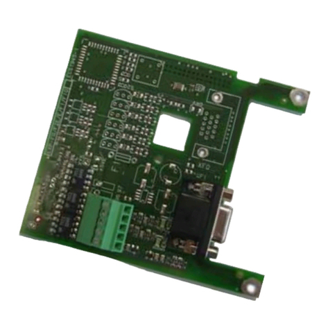
Vista da dietro / Back side

———— Digital Encoder Input Expansion and Encoder Repeater ————
6
2. Fissaggio / Mounting
La scheda EXP-F2E viene fornita con un kit comprendente distanziali ed il collegamento
(C) scheda regolazione / scheda espansione.
1. Spegnere l’azionamento.
2. Fissare con le viti (B) e i distanziali (A) la scheda EXP-F2E alla scheda di regolazione.
3. La scheda EXP-F2E si collega alla scheda di regolazione attraverso il connettore
XH. Su questo connettore sono presenti le alimentazioni e i segnali.
4. Accendere l’azionamento.
The EXP-F2E card is supplied with standoffs and the cable for connection between
regulation and expansion card .
1. Switch the drive off.
2. Fasten the EXP-F2E card to the drive regulation board by means of screws (B) and
standoffs (A).
3. The EXP-F2E card is connected to the regulator card through the XH connector us-
ing the supplied cable. The power supply (+5V) and the control signals are provided
by the drive via the XH connector.
4. Switch on the drive.

7
EXP-F2E
3. Connessione encoder / Encoder connector
3.1 Connessione ingresso encoder / Encoder input
L’interfaccia ingresso encoder permette di collegare un encoder incrementale digitale
attraverso un connettore 15 poli ad alta densità (tipo VGA). L’alimentazione per l’encoder
deve essere fornita esternamente tramite i morsetti 93, 94, 95 secondo il tipo di alimen-
tazione richiesta dall’encoder (+5V oppure 15...24V).
The EXP-F2E expansion board is used to add an additional digital encoder input through
a 15 pin high density connector (VGA type). An external power supply for the encoder
type (+5V or +15V - 24V) is needed. Terminal points 93, 94, 95 are used to connect an
external power supply.
Connector
PIN 1 2 3 4 5 6 7 8
Signal B-
(5V)
+24V
E
C+
(5V)
C-
(5V)
A+
(5V)
A-
(5V) 0VE B+
(5V)
I/O I O I I I I O I
Connector
PIN 9 10 11 12 13 14 15
Signal +5VE
A+
(15V
up to
24V)
A-
(15V
up to
24V)
B+
(15V
up to
24V)
B-
(15V
up to
24V)
C+
(15V
up to
24V)
C-
(15V
up to
24V)
I/O O I I I I I I
exp2F10
ENCODER INPUT
XFI
XFI
ATTENZIONE! I segnali per l’encoder a +5V e quelli per l’encoder a 15...24V non possono
essere connessi contemporaneamente perché i segnali negati dei due tipi
di encoder sono collegati tra loro.
WARNING! 5 VDC encoder signals and 15 - 24 VDC cannot be used simultaneously.
Connector
Terminal 91 92 93 94 95
Signal QC1+ QC1- +5VE +24VE 0VE
exp2F20
ENCODER SUPPLY
XSI
QC+ e QC- sono i segnali dell’ingresso addizionale per il qualicatore dell’impulso di 0.
L’alimentazione dell’encoder deve essere collegata ai segnali +5VE e 0VE per l’encoder
a 5V e ai segnali +24VE e 0VE per l’encoder a 15...24V.
QC+andQC-istheencoderqualier(homepositionsignal)input.Encoderpowersupply

———— Digital Encoder Input Expansion and Encoder Repeater ————
8
should be connected to +5VE and 0VE (for +5V encoder) or +24VE and 0VE (for +15V
to +24V encoder).
3.2 Connessione ripetizione encoder / Encoder repeater connector
L’interfaccia optoisolata uscita encoder permette di ripetere i segnali encoder con livelli
TTL e con livelli HTL contemporaneamente attraverso un connettore 15 poli maschio ad
alta densità (tipo VGA). L’alimentazione per la ripetizione encoder si collega ai morsetti
96, 97 (da 15V a 24V) ed è utilizzata anche per le uscite a +5V.
The optocoupled encoder repeater interface allows the encoder data repeater simultane-
ously with TTL level and HTL level through a 15 pin high density connector (VGA type).
An external power supply (+15V to 24V) is needed through terminals 96, 97. This power
supply is also needed for the +5V repeater.
Connector
PIN 12345678
Signal B-
(TTL) *C+
(TTL)
C-
(TTL)
A+
(TTL)
A-
(TTL) *B+
(TTL)
Connector
PIN 9 10 11 12 13 14 15
Signal * A+
(HTL)
A-
(HTL)
B+
(HTL)
B-
(HTL)
C+
(HTL)
C-
(HTL)
exp2F30
* Reserved
ENCODER REPEATER
XFO
XFO
Connector
Terminal 96 97
Signal +24V DRV 0V DRV
exp2F40
ENCODER REPEATER SUPPLY
XSI
I driver TTL sono protetti da cortocircuito per 1 secondo. Se il cortocircuito permane, pas-
sato questo periodo di tempo, il driver potrebbe danneggiarsi. I driver HTL sono protetti
da cortocircuito attraverso un fusibile da 375mA tipo Bussman MCR 3/8
Per l’alimentazione dell’encoder, è opportuno avere una protezione utilizzando dei fusibili
esterni (max. 500mA).
TTL driver are self protected against short circuit for 1 sec, after this time the drivers could
be damaged. HTL driver are protected against short circuit through 375mA fuse Bussman
MCR 3/8 type..
An external protection is recommended with external power supply using 500mA fuses
at least.

9
EXP-F2E
3.2.1 Divisore ripetizione encoder / divider for encoder repeater
I segnali di ripetizione encoder possono subire una divisione in frequenza rispetto al
segnale in ingresso che proviene dall’encoder da ripetere.
La scelta si fa attraverso dei jumper. Sono disponibili le seguenti divisioni: /1, /2, /4, /8.
La fase dei segnali di uscita rispetto ai segnali di ingresso dipende dal divisore.
Nella tabella viene descritto nei particolari lo sfasamento tra i segnali di ingresso e d’uscita,
considerando il verso positivo dell’encoder in ingresso.
The board has jumpers to set a divider ratio between the encoder repeater frequency
compared to the encoder input data.
The following divider settings are available: /1, /2, /4, /8.
The following table describes the phase shift between input and output.
Divider Description
/1
Canale A out è in fase con A in
A out channel is in phase with A in channel
Canale B out è in fase con B in
B out channel is in phase with B in channel
Canale C out è in fase con C in
C out channel is in phase with C in channel
/2
Canale A out ha i fronti in fase con il fronte di salita o di discesa di A in (dipende dalle condizioni iniziali)
A out channel edges are phased with either rising or falling edges of A in (depending on initial condition)
Canale B out ha i fronti in fase con il fronte di discesa o di salita di A in (dipende dalle condizioni iniziali)
B out channel edges are phased with either falling or rising edges of A in (depending on initial condition)
Canale C out ha il fronte di salita in fase al fronte di salita di C in e il fronte di discesa dopo due fronti
di A in e/o B in
C out channel raising edge is in phase with rising edge of C in and the falling edge after two edges
of A in and/or B in
/4
Canale A out ha i fronti in fase con il fronte di discesa di A in
A out channel is in phase with falling edge of A in channel
Canale B out ha i fronti in fase con il fronte di discesa di A in
B out channel is in phase with falling edge of A in channel
Canale C out ha il fronte di salita in fase al fronte di salita di C in e il fronte di discesa dopo cinque
fronti di A in e/o B in
CoutchannelrisingedgeisinphasewithrisingedgeofCinandthefallingedgeafterveedgesof
A in and/or B in
/8
Canale A out ha i fronti in fase con il fronte di discesa di A in
A out channel is in phase with falling edge of A in channel
Canale B out ha i fronti in fase con il fronte di discesa di A in
B out channel is in phase with falling edge of A in channel
Canale C out ha il fronte di salita in fase al fronte di salita di C in e il fronte di discesa dopo nove fronti
di A in e/o B in
C out channel rising edge is in phase with rising edge of C in and the falling edge after nine edges of
A in and/or B in
exp2F50

———— Digital Encoder Input Expansion and Encoder Repeater ————
10
4. Leds
+5V ������������������������ Il led è acceso quando è presente la tensione +5V fornita dal
Drive.
The led is lit when internal +5V power supply is available from
the Drive.
5ENC����������������������� Il led è acceso quando viene fornita la tensione +5V al morsetto
XSI.
The led is lit when +5V power supply is provided by XSI terminal.
24ENC���������������������� Il led è acceso quando viene fornita la tensione +15...24V al
morsetto XSI.
The led is lit when +15 to 24V power supply is provided by XSI
terminal.
+5VE ����������������������� Il led è acceso quando viene fornita l’alimentazione per i driver
TTL (+5V).
The led is lit when power supply for driver encoder repeater TTL
(+5V) is provided.
DRV������������������������ Il led è acceso quando viene fornita l’alimentazione per i driver
HTL (+15...24V).
The led is lit when power supply for driver encoder repeater TTL
(+15 to 24V) is provided.
5. Jumpers
Name Default
S1 and S2 Setting divider for encoder repeater (see table below) OFF, OFF
ON 0 Channel included in the encoder loss logic
OFF 0 Channel not included in the encoder loss logic
exp2F70
Description
S7 OFF
Settare il Jumper S7 su ON quando occorre l’allarme mancanza encoder anche per il canale
di zero (attivo solo quando viene utilizzato un encoder complementare digitale 15V/24V)
Set Jumper S7 to ON when encoder loss detection is used also for zero channel. (Alarm
active only if a digital encoder with all A, Anot, B, Bnot channels and +15V to 24V power
supply is used)
Encoder divider Jumper S1 Jumper S2
/1 OFF OFF
/2 OFF ON
/4 ON OFF
/8 ON ON
exp2F80
DIVIDER FOR ENCODER REPEATER SELECTION

11
EXP-F2E
6. Caratteristiche tecniche / Technical data
Dimensioni e peso / Dimensions and weight
92.08 mm
105.41 mm
Dimensioni / Dimensions ��������������������� 92.08mm [3.6 inches] x 105.41 mm [4.1 inches]
Peso / Weight ����������������������������� 45 g [ 1.5 oz]
Caratteristiche generali / General data
Alimentazioni interna da drive ����������������� +5VDC
Internal power supply from the drive ������������ +5VDC
Interfaccia ingresso encoder
Tipo interfaccia ���������������������������� optoisolata per encoder digitale incrementale
Selezione sw sul drive ����������������������� ENCODER 2
Ingressi standard��������������������������� A+, A-, B+, B-, C+, C-
Ingresso addizionale camma di zero ������������ QC1+, QC1-
Tensione ingressi encoder ������������������� +5V o 15...24V, selezionabile
Limiti tensioni ingressi standard stato alto (sui pin) (UHigh) 2.5V...5.25V (@5V)
9...26V (@15V...24V)
Limiti tensioni ingressi standard stato basso (sui pin) (ULow) ≤ 0.8V(@5V)
≤ 1.6V(@15V...24V)

———— Digital Encoder Input Expansion and Encoder Repeater ————
12
Corrente ingressi standard (con 5V sui pin) ������ 10mA
Corrente ingressi standard (con 15V sui pin) ����� 8mA
Corrente ingressi standard (con 24V sui pin) ����� 13mA
Tensione (Corrente) ingresso addizionale camma di zero 15...30V (4.5...9mA)
Frequenza di ingresso massima ��������������� 150kHz
Ripetizione encoder
Tipo interfaccia ���������������������������� dati encoder digitale incrementale differenziale
(optoisolati)
Uscite standard ���������������������������� A+, A-, B+, B-, C+, C-
Livelli di uscita ����������������������������� standard TTL e HTL
Limiti tensioni uscite TTL stato alto (sui pin) (UHigh TTL) ≥ 2.5V
Limiti tensioni uscite TTL stato basso (sui pin) (ULow TTL) ≤ 0.5V
Caricabilità uscite TTL ����������������������� 20mA max cad.
Collegamento in parallelo ingressi standard AVy a uscita TTL 3 ingressi
Limiti tensioni uscite HTL stato alto (sui pin) (UHigh HTL) ≥ alimentazione -3.5V
Limiti tensioni uscite HTL stato basso (sui pin) (ULow HTL) ≤1.5V
Caricabilità uscite HTL����������������������� 80mA max ognuna
Collegamento in parallelo ingressi standard AVy a uscita HTL 8 ingressi @ 15V
5 ingressi @ 24V
Ritardo tra encoder da ripetere encoder ripetuto��� 5µs per Encoder 1
2µs per Encoder 2
Frequenza max ���������������������������� 150kHz
Alimentazione ripetizione encoder�������������� 15...24V con limiti -10% +20%
Assorbimento max alimentazione ripetizione encoder 600mA
Encoder interface
Interface type������������������������������ optocoupled digital encoder input interface
Encoder sw selection������������������������ ENCODER 2
Standard inputs ���������������������������� A+, A-, B+, B-, C+, C-
Additionalinputforencoderqualier ������������ QC1+,QC1-(optocoupled)
Encoder power supply ���������������������� +5V or 15V to 24V, selectable
Voltage input range High level (on pin) ) (UHigh) ������ 2.5V up to 5.25V (@5V)
9 up to26V (@15V to 24V)
Voltage input range Low level (on pin) ) (ULow) ������ ≤0.8V(@5V)
≤1.6V(@15Vto24V)
Current input value (@ 5V, per pin)������������� 10mA
Current input value (@ 15V, per pin)������������ 8mA
Current input value (@ 24V, per pin)������������ 13mA
Voltage(Current)valueadditionalinputforencoderqualier 15upto30V
(4.5upto 9mA)

13
EXP-F2E
Max Frequency input ������������������������ 150kHz
Encoder repeater
Interface type������������������������������ optocoupled digital encoder
Standard outputs ��������������������������� A+, A-, B+, B-, C+, C-
Output voltage level������������������������� standard TTL and HTL
Voltage output range TTL high level (on pin) (UHigh TTL) ≥2.5V
Voltage output range TTL low level (on pin) (ULowTTL) ≤0.5V
Driving capability TTL ����������������������� 20mA max each
Max parallel connection for drives input (TTL) ���� 3 inputs
Voltage output range HTL high level (on pin) (UHigh HTL)� ≥powersupplyless3.5V
Voltage output range HTL low level (on pin) (ULow HTL) ≤1.5V
Max output current HTL���������������������� 80mA max each
Max parallel connection for drives input (HTL) ���� 8 inputs @ 15V
5 inputs @ 24V
Repeat output delay ������������������������ 5µs for Encoder 1
2µs for Encoder 2
Max frequency ����������������������������� 150kHz
Power supply������������������������������ 15V to 24V -10%..+20%
Power requirements ������������������������ 600mA
Temperatura
Temperatura di immagazinamento: ������������� -20°... +70°C (-68...+158°F)
Temperatura di funzionamento: ���������������� 0°... +55°C (32...+131°F)
Queste temperature sono adeguate a quelle dell’inverter a cui la scheda è collegata.
Temperature
Storage temperature:������������������������ -20°... +70°C (-68...+158°F)
Operating temperature: ���������������������� 0°... +55°C (32...+131°F)
These temperatures are adequate to those of the drive, to which the card is connected.

———— Digital Encoder Input Expansion and Encoder Repeater ————
14
7. Accessori / Accessories
Connettore XFI ��������������� connettore vaschetta 15 poli alta densità (tipo VGA) maschio.
Custodia connettore XFI �������� custodia per connettore a vaschetta standard 9 poli con basso
prolo.
Esempi: codice AMP: 0-748676-1
codice 3M: 3357-6509
Connettore XFO �������������� connettore vaschetta 15 poli alta densità (tipo VGA) femmina.
Custodia connettore XFO ������� custodia per connettore a vaschetta standard 9 poli con basso
prolo.
Esempi: codice AMP: 0-748676-1
codice 3M: 3357-6509
Fusibile per driver HTL ��������� Fusibile 375mA Bussmann tipo MCR 3/8
XFI Connector ���������������� 15 pin high density (VGA type), male.
XFI connector cover ����������� Standard9pinlowprole.
Example manufacturer code: AMP: 0-748676-1
3M: 3357-6509
XFO Connector ��������������� 15 pin high density (VGA type), female.
XFI connector cover ����������� Standard9pinlowprole.
Example manufacturer code: AMP: 0-748676-1
3M: 3357-6509
Driver HTL fuse ��������������� 375mA Bussmann type MCR 3/8
8. Sezione massima cavi / Maximum wire sizes
Terminals & Connector mm
2
AWG
91, 92, 93, 94, 95, XFI 0.14 … 1.5 28 … 16
expF40

15
EXP-F2E
9. Esempio di utilizzo / Example of application
Tach Follower
M
EM
E
Encoder
supply
+5V
Encoder
supply
+5V
XE
Drive
EXP-FI
Drive + DGFC
XE
XFI

MANUALE EXP-F2E /HI /HGB 04/99
Rev. 0.2 / 5.3.09
1S5E45
Gefran worldwide
GEFRAN BENELUX
Lammerdries-Zuid, 14A
B-2250 OLEN
Ph. +32 (0) 14248181
Fax. +32 (0) 14248180
GEFRAN BRASIL
ELETROELETRÔNICA
Avenida Dr. Altino Arantes,
377/379 Vila Clementino
04042-032 SÂO PAULO - SP
Ph. +55 (0) 1155851133
Fax +55 (0) 1132974012
GEFRAN DEUTSCHLAND
Philipp-Reis-Straße 9a
63500 SELIGENSTADT
Ph. +49 (0) 61828090
Fax +49 (0) 6182809222
SIEI AREG - GERMANY
Gottlieb-Daimler-Strasse 17/3
D-74385 Pleidelsheim
Ph. +49 7144 89 736 0
Fax +49 7144 89 736 97
GEFRAN - FRANCE
4, rue Jean Desparmet - BP
8237
69355 LYON Cedex 08
Ph. +33 (0) 478770300
Fax +33 (0) 478770320
GEFRAN SUISSE SA
Rue Fritz Courvoisier 40
2302 La Chaux-de-Fonds
Ph. +41 (0) 329684955
Fax +41 (0) 329683574
GEFRAN SIEI - UK Ltd.
7 Pearson Road, Central Park
TELFORD, TF2 9TX
Ph. +44 (0) 845 2604555
Fax +44 (0) 845 2604556
GEFRAN INC
Sensors and Automation
8 Lowell Avenue
WINCHESTER - MA 01890
Toll Free 1-888-888-4474
Ph. +1 (781) 7295249
Fax +1 (781) 7291468
Motion Control
14201 D South Lakes Drive
NC 28273 - Charlotte
Ph. +1 704 3290200
Fax +1 704 3290217
salescontact@sieiamerica.com
GEFRAN INDIA PRIVATE
LIMITED
Survey No.: 129/1, Nandan
Park
Plot No.: 6, Chakankar Mala
Baner-Balewadi Road, Baner
Pune 411045, MH, INDIA
Ph. +91 20 66400400
Fax +91 20 66400401
GEFRAN SIEI - ASIA
Blk. 30 Loyang way
03-19 Loyang Industrial Estate
508769 SINGAPORE
Ph. +65 6 8418300
Fax. +65 6 7428300
GEFRAN SIEI Electric
Block B, Gr.Flr, No.155, Fu Te Xi Yi Road,
Wai Gao Qiao Trade Zone
200131 Shanghai
- CHINA
Ph. +86 21 5866 7816
Ph. +86 21 5866 1555
GEFRAN SIEI DRIVES TECHNOLOGY
No.1265, Beihe Road,
Jiading District
201821 Shanghai - CHINA
Ph. +86 21 69169898
Fax +86 21 69169333
GEFRAN S.p.A.
Via Sebina 74
25050 Provaglio d’Iseo (BS)
ITALY
Ph. +39 030 98881
Fax +39 030 9839063
www.gefran.com
Drive & Motion Control Unit
Via Carducci 24
21040 Gerenzano [VA]
ITALY
Ph. +39 02 967601
Fax +39 02 9682653
Technical Assistance :
Customer Service :
Ph. +39 02 96760500
Fax +39 02 96760278
Table of contents
Other gefran Media Converter manuals
Popular Media Converter manuals by other brands

Radyne ComStream
Radyne ComStream SFC6400A Installation and operation manual

Quark-Elec
Quark-Elec QK-A032 manual

Shenzhen Shunxun Electronics
Shenzhen Shunxun Electronics SX-VH03 operating instructions

Baumer
Baumer HUBNER Low Harmonics EExOG 9 S Mounting and operating instructions

Micronor
Micronor MR330 Series instruction manual

Ltech
Ltech 2272700 quick start guide