Important
If a decoder will not react after a programming cycle, most probably its address has been
altered inadvertently. To resolve this situation, either try all address settings, or Intelliboxs, or
Loktools address search function.
Wrong settings may be corrected by resetting the decoder using programming function 10.
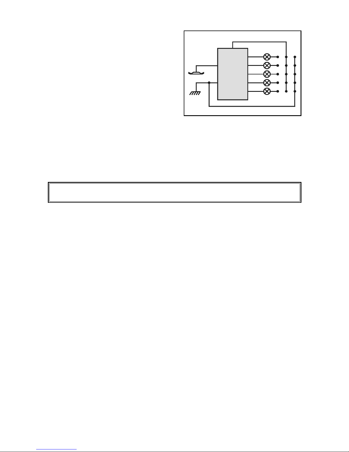
Programming of Uhlenbrock Function Decoders
by a Märklin Central Unit
Follow exactly these steps when programming the decoder.
Do not push any other keys.
1. Preparation
sConnect a Märklin central unit together with a control 80/80f or a control unit
to the track.
sSwitch off power supply for at least ten seconds, then switch on again.
All digital signals that may possibly interfere have died away.
sKey in decoder address.
Every new decoder is set to 01.
sHold kno in direction reversal position for at least 8 secs.
Decoder changes over to programming mode.
2. Programming of individual functions
It does not matter whether functions are programmed individually or consecutively.
Functions not called up remain unaltered.
A lamp connected to the f1 output will flash four times to acknowledge a programming step.
2.1 Address
sCall up function: Key in 01 and shortly push kno to reverse - a lamp will flash
sSet value: Key in 01- 80 and shortly push kno to reverse - a lamp will flash
2.2 Selection of Data Format
sCall up function: Key in 02 and shortly push kno to reverse - a lamp will flash
sSet value: Key in 01 for the extended format (Gauge I format) and shortly push kno to reverse - the lamp will flash
Key in 02 for the old data format (dou le frequency) and shortly push kno to reverse - the lamp will flash
The old format renders functions f1 to f4 , the extended Motorola format will also utilize the direction info.
2.3 Output dimming
sCall up function: for f1 and f2 - key in 03 and shortly push kno to reverse - the lamp will flash
for f3, f4, and function - key in 04 and shortly push kno to reverse - the lamp will flash
sTo set the duty cycle: 25% - key in 01 and shortly push kno to reverse - the lamp will flash
50% - key in 02 and shortly push kno to reverse - the lamp will flash
75% - key in 03 and shortly push kno to reverse - the lamp will flash
100% - key in 04 and shortly push kno to reverse - the lamp will flash
2.4 Defining of Flasher Outputs
sCall up function: To assign frequency#1- key in 06 and shortly push kno to reverse - the lamp will flash
To assign frequency#2 key in 08 and shortly push kno to reverse - the lamp will flash
sSet value: Flashing outputs-key in 01-31and shortly push kno to reverse - the lamp will flash
No flashing at all-key in 32 and shortly push kno to reverse - the lamp will flash
The code value is derived from an addition of the output weights: f1 = 1, f2 = 2, f3 = 4, f4 = 8, function = 16.
When e.g. f1 and f3 are set to flashing, the code value must be 05 (1 + 4).
2.5 Setting the frequency
sCall up function: To call frequency#1 - key in 07 and shortly push kno to reverse - the lamp will flash
To call frequency#2 - key in 09 and shortly push kno to reverse - the lamp will flash
sSet value: Rate 8 times per sec - key in 01 and shortly push kno to reverse - the lamp will flash
Rate 1 time per sec - key in 08 and shortly push kno to reverse - the lamp will flash
Rate 1 time per 8 sec - key in 64 and shortly push kno to reverse - the lamp will flash
The allowed values range from 01 -79. In analogy to 2.4 the actual flash period is determined by adding the rate weights.
2. Reset
sKey in 10 and shortly push kno to reverse - the lamp will flash
The decoder will be set to the preset values: Address 01, extended Motorola data format,
no flashing, frequency rates set to 1 time per sec, and 100% duty cycle.
3. Leaving Programming ode
s Key in 80 and shortly push kno to reverse.
Decoder returns to its normal operating mode.
01
01
32
08
04
-
Default setting