TRAXX TITAN 500 Installation instructions

1
TITAN 500
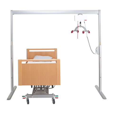
FREESTANDING OVERHEAD PATIENT LIFT
ASSEMBLY, OPERATION & MAINTENANCE

2
PARTS LIST
Description Quantity
1. Upper Support (Red/Blue Marking) 2
2. Lower Support (Green/Blue Marking) 2
3. Support Base (Blue Marking) 2
4. Overhead Transverse Beam 1
5. Flat Lower Gusset (Blue/Green Marking) 4
6. Bent Upper Gusset (Red Marking) 4
7. Lift Motor 1
8. Four Point Lift Bar 1
9. Universal Sling 1
10. Remote Control 1
11. Emergency Remote Control 1
12. Battery Charger 1
13. Manual / Warranty 1
14. Assembly Kit 1
3½” Bolts – Red – 8 total, 4 with washers
3” Bolts – Green – 4 total
2¾” Bolts – Blue – 10 total
Nylock Nuts – 22 total
Plastic Caps – 44 total

3
The intended use of this lifting device is for the safe lifting and transfer of an individual
between the posts from one resting surface to another (such as a bed to a wheelchair).
Traxx Mobility Systems recommends that the transfer of a patient is fully risk assessed
and conducted safely. The Titan 500 is suitable for patient in the sitting,
sitting/recumbent and recumbent positions. The Titan 500 is designed to support and
promote safe patient handling and transfer for both the patient and the caregiver.
Do not operate this equipment without first reading and understanding this manual. Use
only as intended. This product may cause serious injury if not installed and operated
according to the manual.
If you are unable to understand the warnings, cautions or instructions, contact a
healthcare professional or Traxx Mobility Systems before attempting to use this
equipment. Otherwise, injury or damage may occur.
Failure to observe the warnings listed below could result in serious injury.
DO NOT lift a patient unless you are trained and competent to do so.
DO NOT attempt any transfer without approval of the patient’s physician, nurse
or medical attendant. Thoroughly read the instruction in the manual, observe a
trained team of experts perform the lifting procedures and then perform the entire
lift procedure several times with proper supervision and a capable individual
acting as a patient before attempting to use this device on a patient.
ALWAYS familiarize yourself with operating control and safety features of the
lift before lifting a patient. ALWAYS carry out lifting operations according to the
instructions in the manual
The Titan 500 is NOT a transport device. It is intended to transfer an individual
from one resting surface to another (such as a bed to a wheelchair). DO NOT
move the frame with a patient suspended in the sling.
Transfers should only take place between the supports of the Titan 500. DO NOT
swing the patient sideways out from under the overhead beam.
ALWAYS keep patient’s weight centered under the overhead beam. The beam
should cross the patient’s chest to ensure a straight lift.
ALWAYS use lift caster brakes (if equipped) while lifting or transferring a
patient.
NEVER leave a patient unattended while the lift is in use.
KEEP the batteries fully charge. Place the batteries on charge whenever it is not
in use. If it is more convenient to do so, place on charge every night. The charger
will not allow the batteries to overcharge.
NEVER run the batteries completely flat. NEVER store the batteries for long
periods without regular charging throughout the storage period.
DO NOT use the lift in a shower. DO NOT charge the lift in a bathroom or
shower.
NEVER use a sling or lift belt that is frayed or damaged.
The lift is NOT a toy. ALWAYS keep it away from children and pets.

4
TITAN 500 PATIENT LIFT MANUAL
UNPACK
Inspect the exterior of each box for any damage that may have
occurred during shipping. Inspect interior contents for same. If
anything appears damaged, call customer service at (855) 872-9967.
Carefully remove the patient lift parts from the boxes. Reference the
Parts List below and make sure all parts are included. Parts have
been color-coded for easy assembly.
We recommend you watch our Assembly Video at
www.youtube.com/traxxmobilitysystems before proceeding.

5
Survey the room where you plan to install the system and make sure
the room meets all requirements and is free of debris. For safety
reasons, make sure patient is not in bed or in room when installing
overhead lift
We recommend that two adults assemble the lift. Read all instructions
before beginning assembly. All hardware features a 9/16th inch /
14mm hex head.
ASSEMBLY
Assemble a Lower Support (Green/Blue Marking) with a Support
Base (Blue Marking) using two Flat Lower Gussets (Blue/Green
Marking.
Four 2¾” Bolts (Blue) will attach the Flat Lower Gusset to the Support
Base. Two 3” Bolts (Green) will attach the Flat Lower Gusset to the
Lower Support.

6
Place Base Support with Glides/Casters facing up. Insert two 2¾”
Bolts (Blue) through the two right holes on the Base Support. Flip the
Support Base so bolts stick up.
Align Flat Gusset as shown below. Insert two 2 ¾” Bolts (Blue)
through the bottom of the Flat Gusset. Insert two 3” Bolts (Green)
through the side of the Flat Gusset. Follow the color coding on the
gussets.

7
Place the Base Support over the Flat Gusset.
Place Lower Support over Flat Gusset.

8
Place Flat Gusset over top of Base Support and Lower Support.
Fasten Nylock Nuts on all six bolts. Do not over-tighten. Repeat
process for second Lower / Base Support.
Next, attach the Bent Upper Gussets to the Upper Support. Select
four 3½” Bolts with Washers. One washer will go against the bolt hex
head and the other will go against the Nylock Nut once fully
assembled.

9
Select two 3 ½” Bolts with washers.
Next, select an opposite pair of Bent Upper Gussets.

10
The flat part of the Bent Upper Gusset is attached to the Upper
Support. The bent part of the Bent Upper Gusset is attached to the
Overhead Transverse Beam.
Place two 3 ½” Bolts through Bent Upper Gusset and Upper Support.

11
Place opposite paired Bent Upper Gusset on other side of Upper
Support. Add Washers to bolts before tightening Nylock Nuts.

12
The Bent Upper Gussets should bend away from the Upper Support
in order to support the wider Overhead Transverse Beam.
Repeat for second Upper Support.

13
Join the assembled Lower Support with the assembled Upper
Support. Line the two pieces up as shown below.
Slide supports together until they stop at base. Do not install the
support hardware at this time.

14
Repeat process with 2nd Upper Upright Support and Lower Upright
Support.
You may lean Upright Support against bed for convenience during
this step.

15
Attach Transverse Beam, with open channel downward, to one
Upright Support.

16
Install two 3 ½” Bolts with Nylock Nuts. Do not fully tighten nuts
completely at this time.
Carefully install Lift Motor by sliding trolley wheels into bottom
channel of open end of Transverse Beam. Roll Lift Motor to other end
of frame. Be careful not to let Lift Motor roll out open end and fall.

17
Slide Transverse Beam into opposite Upright Support and attach with
two 3 ½” Bolts with Nylock Nuts. Tighten all hardware connecting
Beam with Upright Supports. Do not over-tighten.

18
ATTENTION
When raising the frame to the higher working height, lift one Upright
Support at a time. Do not attempt to lift both at the same time. Before
lifting the first Upright Support, place Lift Motor on opposite (lower)
end of the frame to keep it from rolling while lifting.
Place foot on Upright Support Base and lift the Upper Upright
Support. Align holes on Upright Support pieces and attach one 2¾”
Bolt with nut and tighten. Repeat on other side of frame.
Cover all nut and bolt heads with the included nut caps.

19
Connect Remote Control by plugging into control panel. Next, place
Lift Bar on bed and lower Lift Belt to connect them together.
Attach Lift Bar to the Lift Belt with the included stainless steel Link.

20
Hand-tighten Link to close completely. Raise Lift Belt and Lift Bar to
Motor Housing.
Attach the Remote Control using the Hook & Loop tape included and
place in a convenient location. We suggest attaching it to the Lift Bar
or Lift Motor.
Table of contents
