TreeGreen energyEGG User manual

energyEGG Assembly
Instructions v6.0
Version : v6.0
Date : 4th May 2012
TreeGreen Limited
Digital Enterprise Centre,
CBLZ Building,
190 Cathedral St
Glasgow,
G4 OND
Stuart Henderson
07941 222 437
stuart@treegreen.net

1
energyEGG Assembly Instructions
Equipment Required
Phillips head screwdriver
Components
1 x EG-001 : Main Base
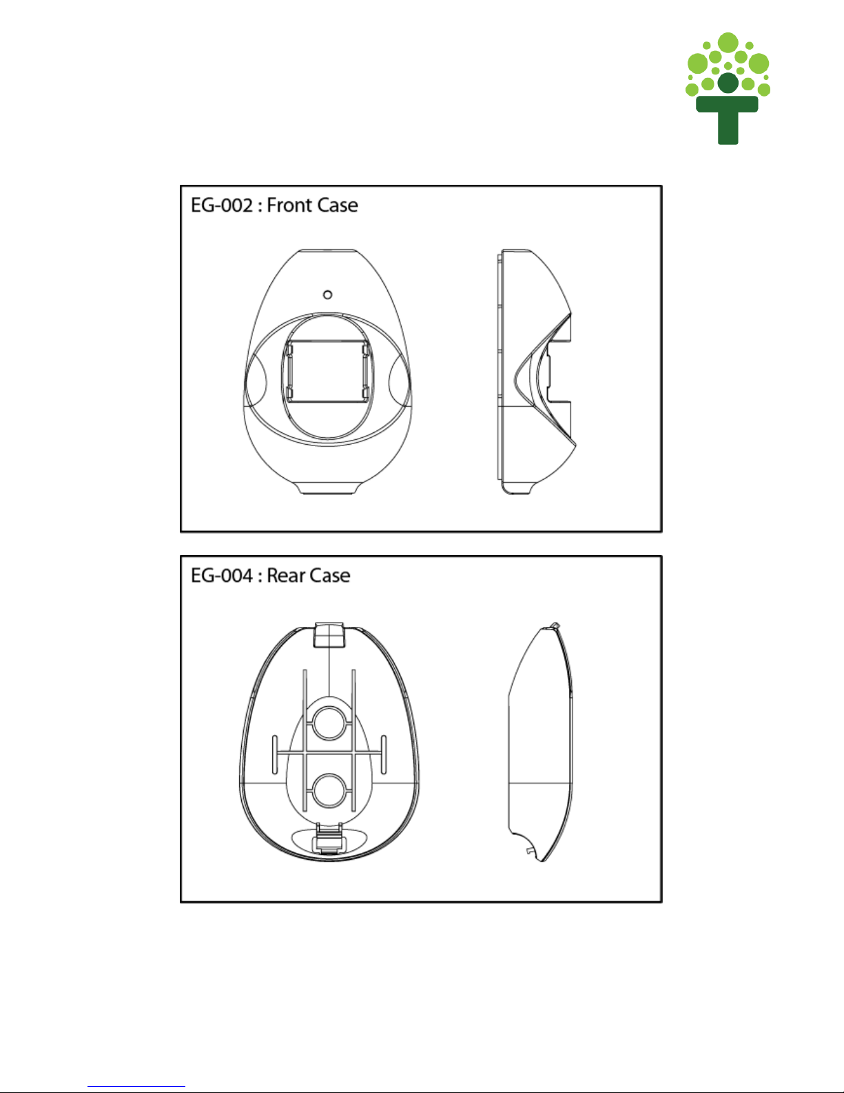
1 x EG-002 : Front Case
1 x EG-004 : Rear Case
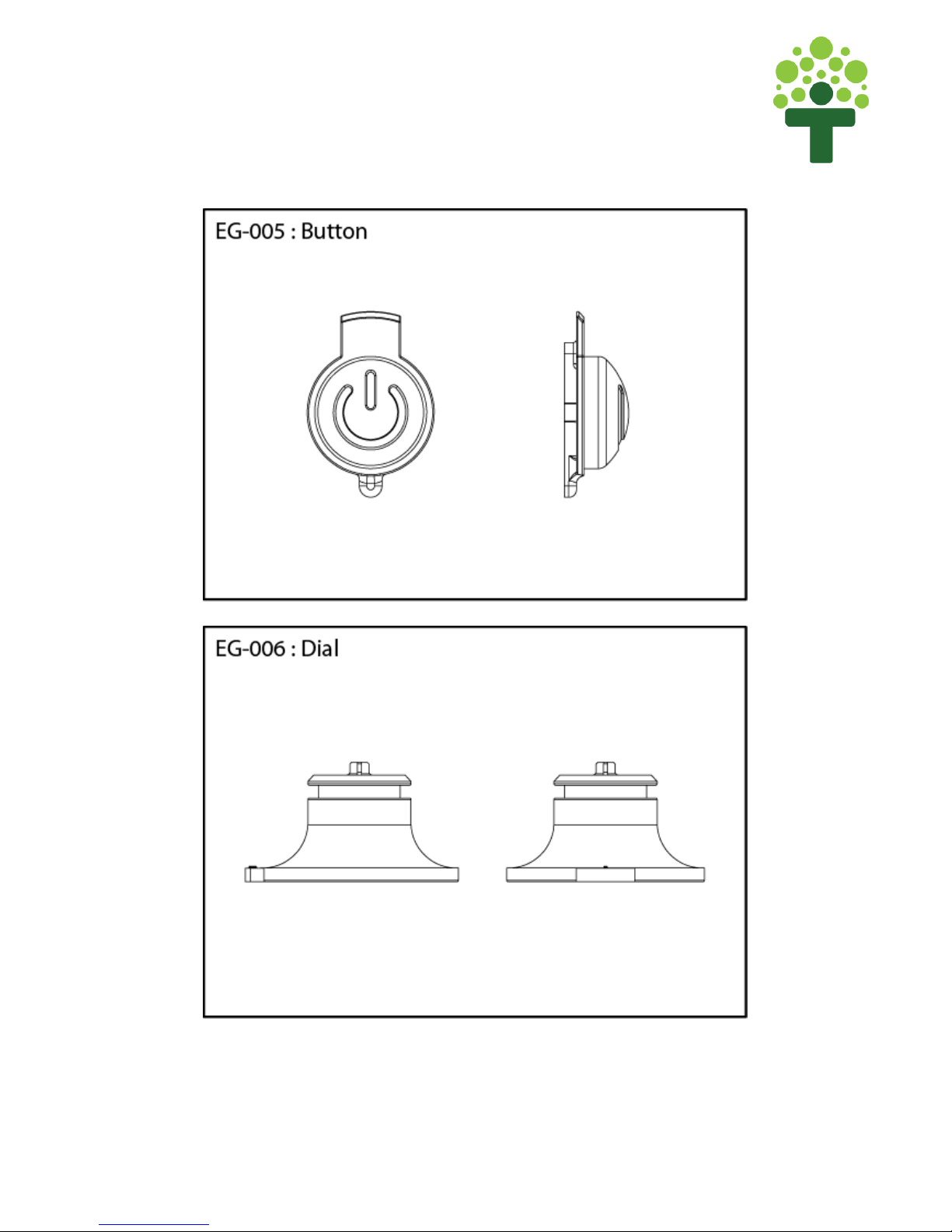
1 x EG-005 : Button
1 x EG-006 : Dial
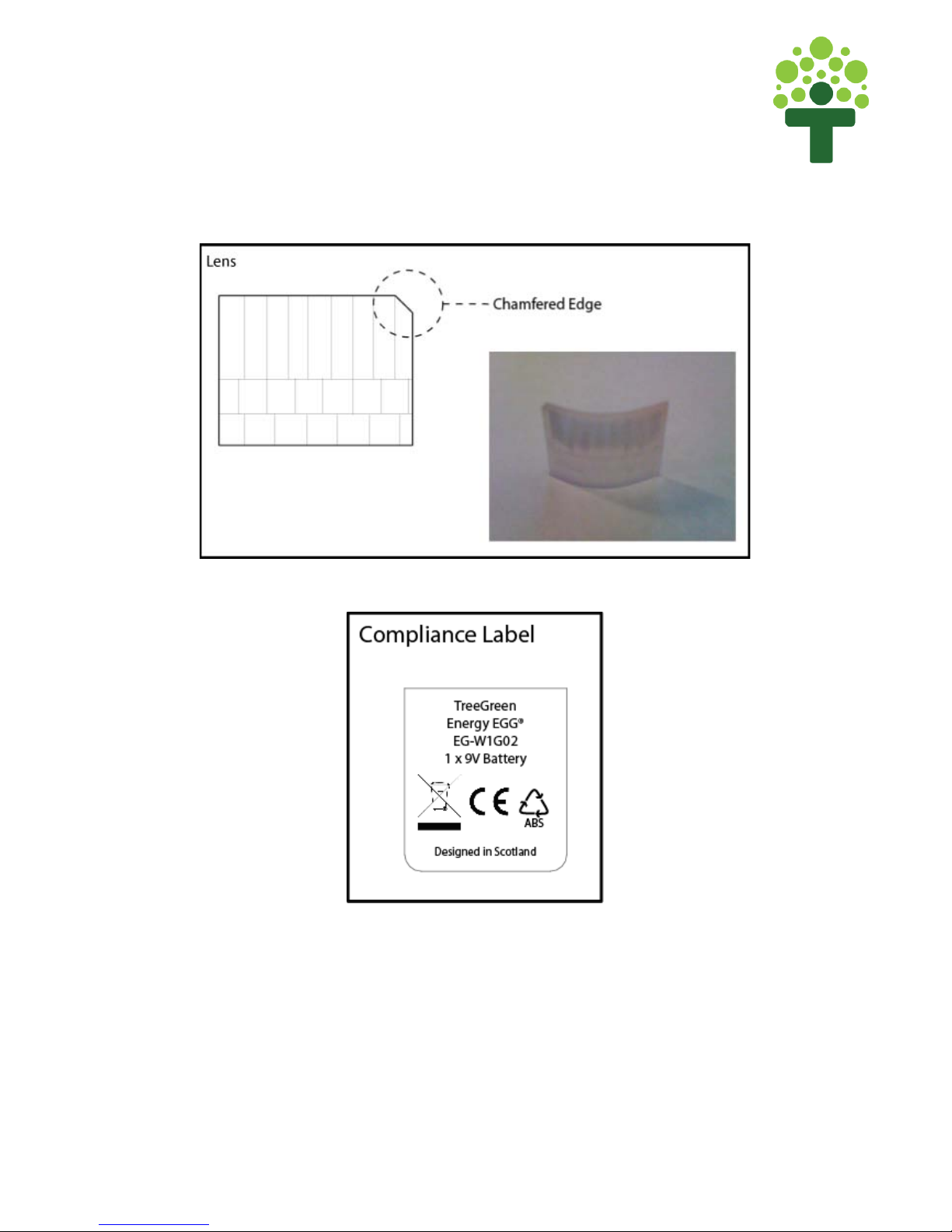
1 x Lens
1 x PCB (Printed Circuit Board)
4 x Screws
1 x Compliance Label
2
energyEGG Assembly Instructions
3
energyEGG Assembly Instructions

4
energyEGG Assembly Instructions
5
energyEGG Assembly Instructions
6
energyEGG Assembly Instructions
Before beginning assembly please note:
-Be careful when handling the PCB(Printed Circuit Board) as touching the
Sensor can seriously impair functionality.
-Be careful when handling the Lens as it is sensitive and easily scratched –
this can significantly diminish the functionality of the lens.
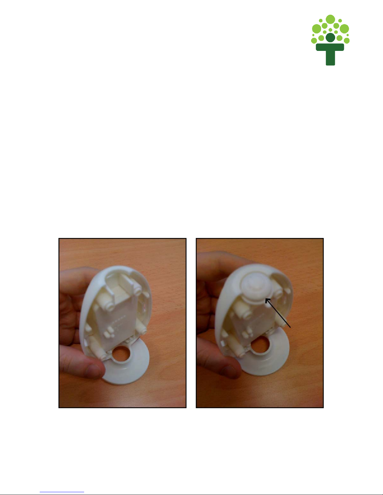
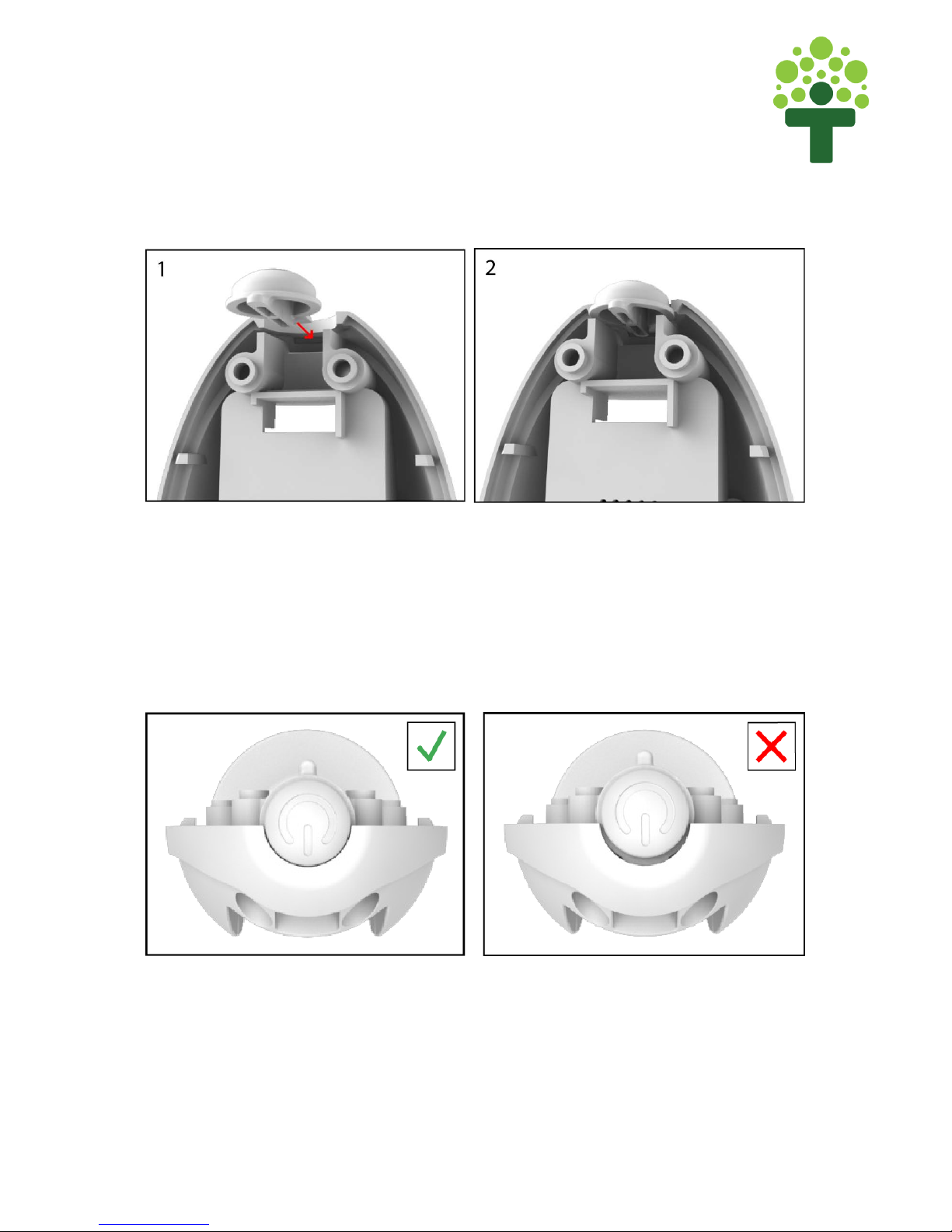
Step 1 : Insert Button (EG-005)
Insert Button (EG-005) into the slot at the top of the Main Base (EG-001) as
shown in Figure 1a. The Button should slide into the ledge as shown in Figure
1b.
Figure 1a - Insert Button in Main Base
7
energyEGG Assembly Instructions
Figure 1b - Slide Button into Ledge
The Button should sit flush in the Main Base when inserted correctly. When
inserted correclt, there should be no gap between the Button and Main Base
(See Figure 1c).
Figure 1c - There should be no gap between Button and Main Base
8
energyEGG Assembly Instructions
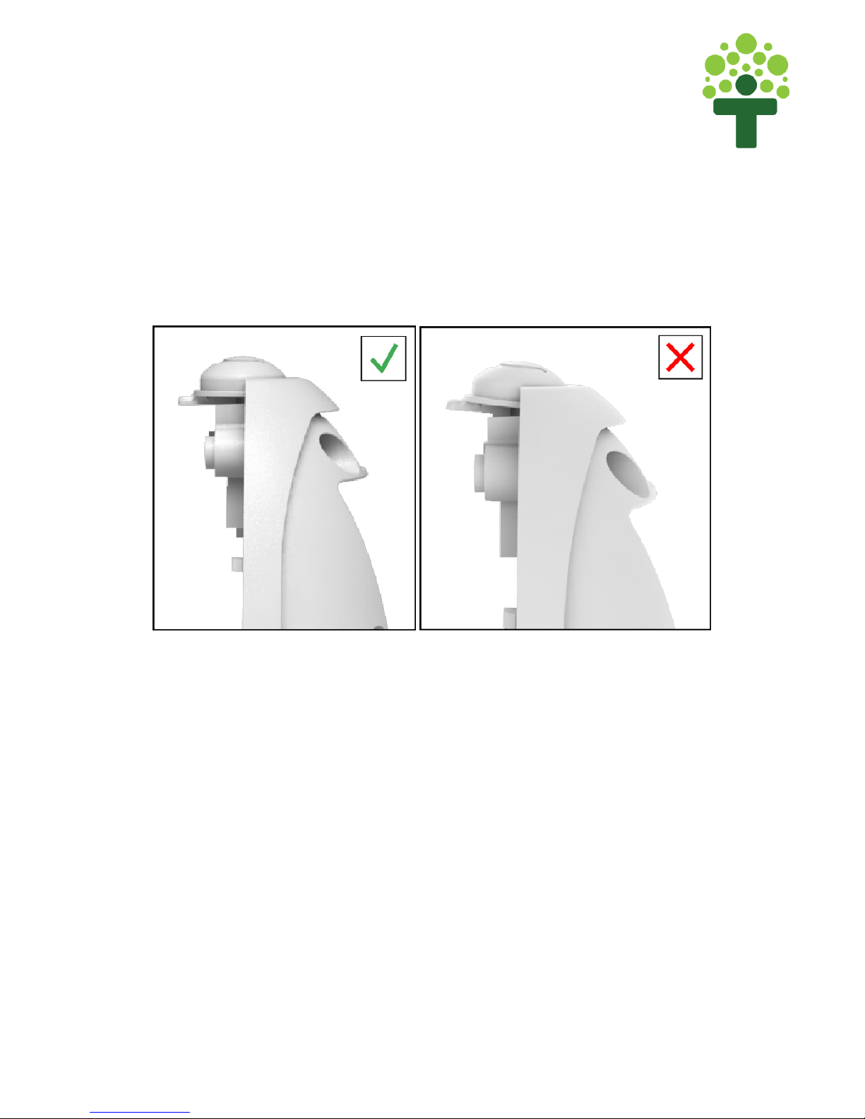
The Button should also be flush and parallel with the top of the Main Base
(See Figure 1d).
Figure 1d – Button should fit into the Main Base and not be angled

9
energyEGG Assembly Instructions
Step 2 : Prepare PCB
The first step of inserting the PCB is to tie a knot in the battery fly wire, around
5cm from the base of the PCB (see figure 2a)
Figure 2a - Tie knot in the battery fly lead

10
energyEGG Assembly Instructions
Ensure that the Pot on the PCB is in the right position (see Figure 2b). The pot
should be slightly angled forward away from the PCB. Figure 2c highlights the
correct and incorrect alignment for the Pot.
Figure 2b - Pot Alignment
Figure 2c – Correct and Incorrect Pot Alignment
11
energyEGG Assembly Instructions
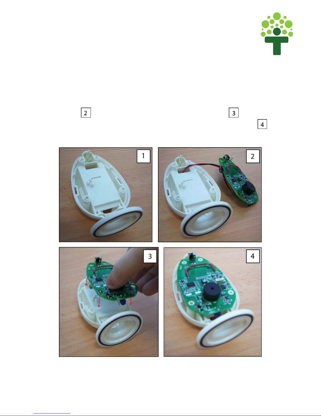
Step 3 : Insert PCB
Figure 3a shows a step by step guide to inserting the PCB into the Main Base.
First thread the battery connector through the gap at the top of the Main Base
as show in . Next, place the PCB down onto the Main Base ( ), aligning
the four screw holes on the PCB with the screw bosses on the Main Base (
).
Figure 3a - Insert PCB onto Main Base
12
energyEGG Assembly Instructions
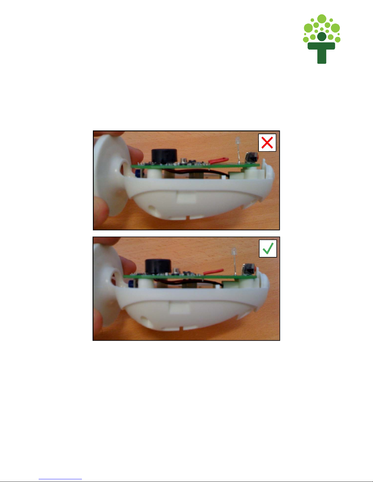
The PCB should now sit flush and tight against the Main Base as shown in
Figure 3b. Please ensure that the PCB is tight against the Main Base at each of
the four screw bosses.
Figure 3b - PCB should be flush with Main Base and aligned with Button
The Button (EG-005) aligns with the red button on the PCB and should ‘click’
when depressed. Figure 3b shows the correct and incorrect alignment of the
Button EG-005 to the PCB button.
13
energyEGG Assembly Instructions
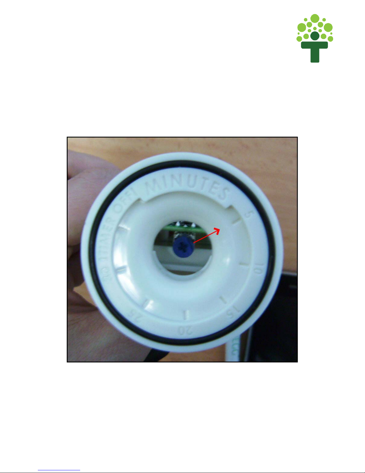
Step 4 : Insert Dial
Before inserting the Dial in the Main Base, please ensure that the blue pot is
pointing towards the ‘5’ setting on the Main Base (see Figure 4a).
14
energyEGG Assembly Instructions
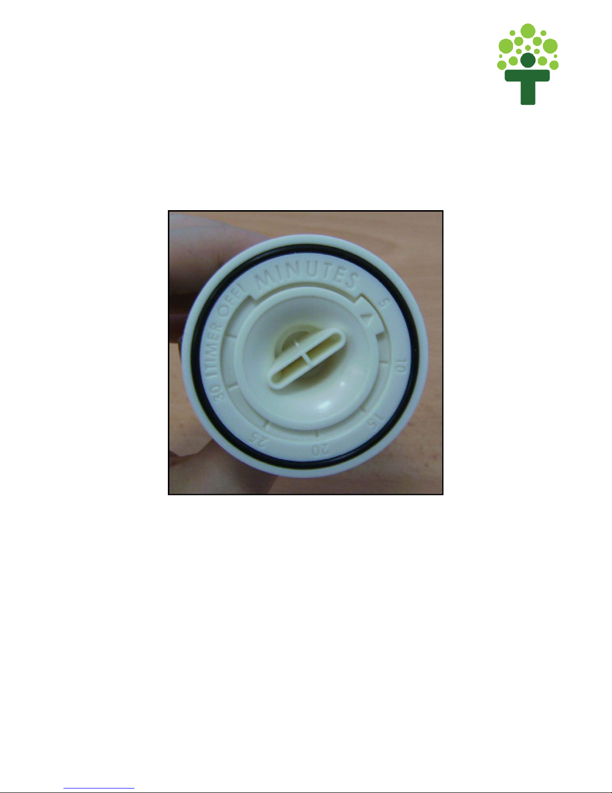
Now Place the Dial (EG-006) into the bottom of the Main Base (EG-001). The
Dial (EG-006) should point to the 5 Minute setting on the Main Base (See
Figure 4b).
Figure 4b - Dial pointing towards the '5' minute setting
When inserted correctly, the Dial should sit tight and flush to the Main Base.

15
energyEGG Assembly Instructions
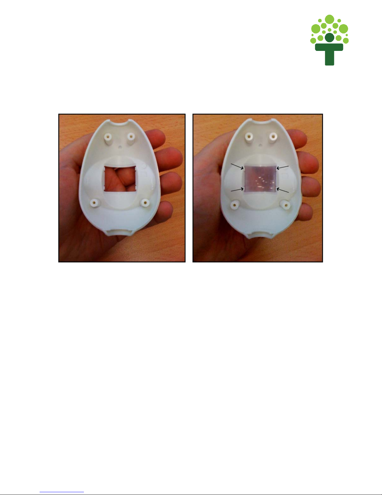
Step 5 : Attach Lens to Front Case
Attach the Lens to the Front Case (EG-002), with the smooth, glossy surface
facing out. To do so, align the Lens so that chamfered corner is at the top right
hand edge of the enclosure and clip into place (Figure 5a).
Figure 5a - Ensure the chamfered edge of the Lens is at the top right corner
16
energyEGG Assembly Instructions
The Lens should ‘click’ into place at each of the four areas highlighted in
Figure 5b.
Figure 5b - Lens should 'click' into place.
With the Lens correctly attached to the Front Case, apply a small amount of
adhesive to hold the lens firmly in place.
17
energyEGG Assembly Instructions
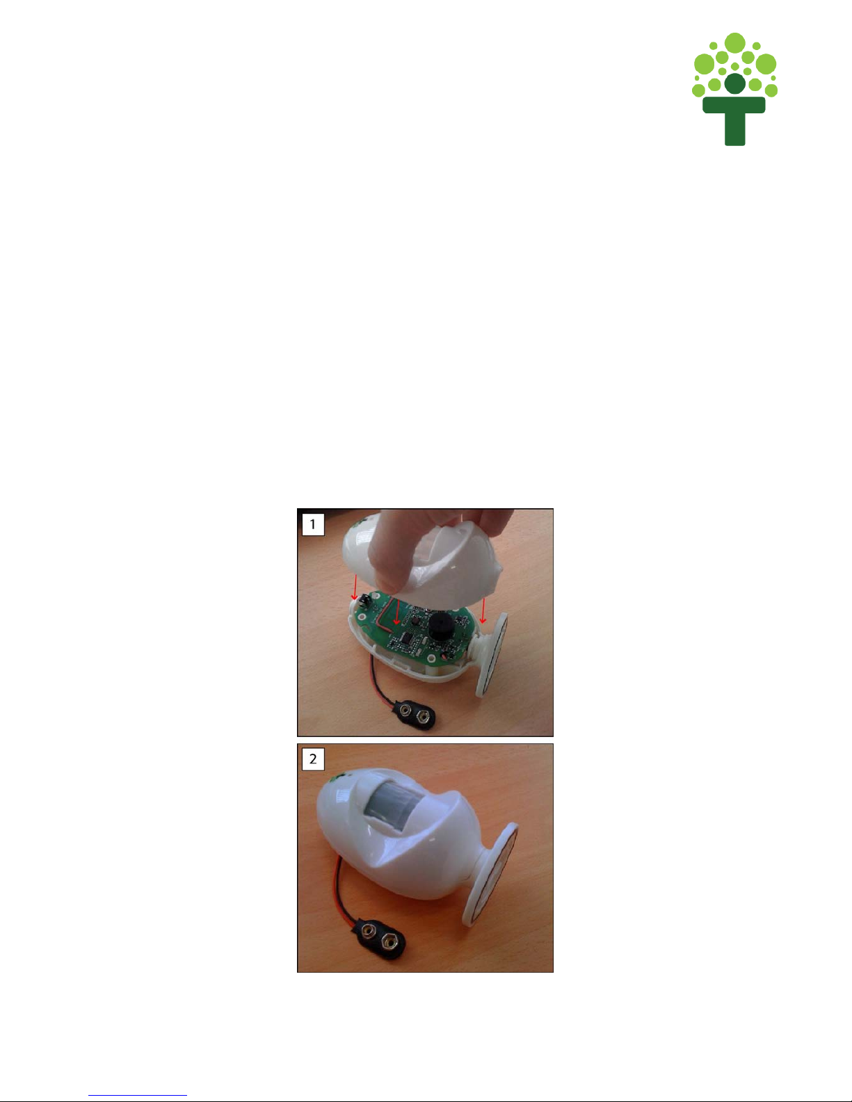
Step 5 : Attached Front Case to Main Base
Now take the assembled Front Case(EG-002) and the assembled Main
Base(EG-001) and piece together (see Figure 5a). The Front Case (EG-002)
should fit flush with the Main Base (EG-001) and no components should be
loose. If assembled correctly:
-The Button (EG-005) should click when pressed and then return to its
original position.
-The Dial (Eg-006) should be able to rotate freely and click at each
setting.
-No components should be loose or rattle.
Figure 5a - Attach Front Case to Main Base
18
energyEGG Assembly Instructions
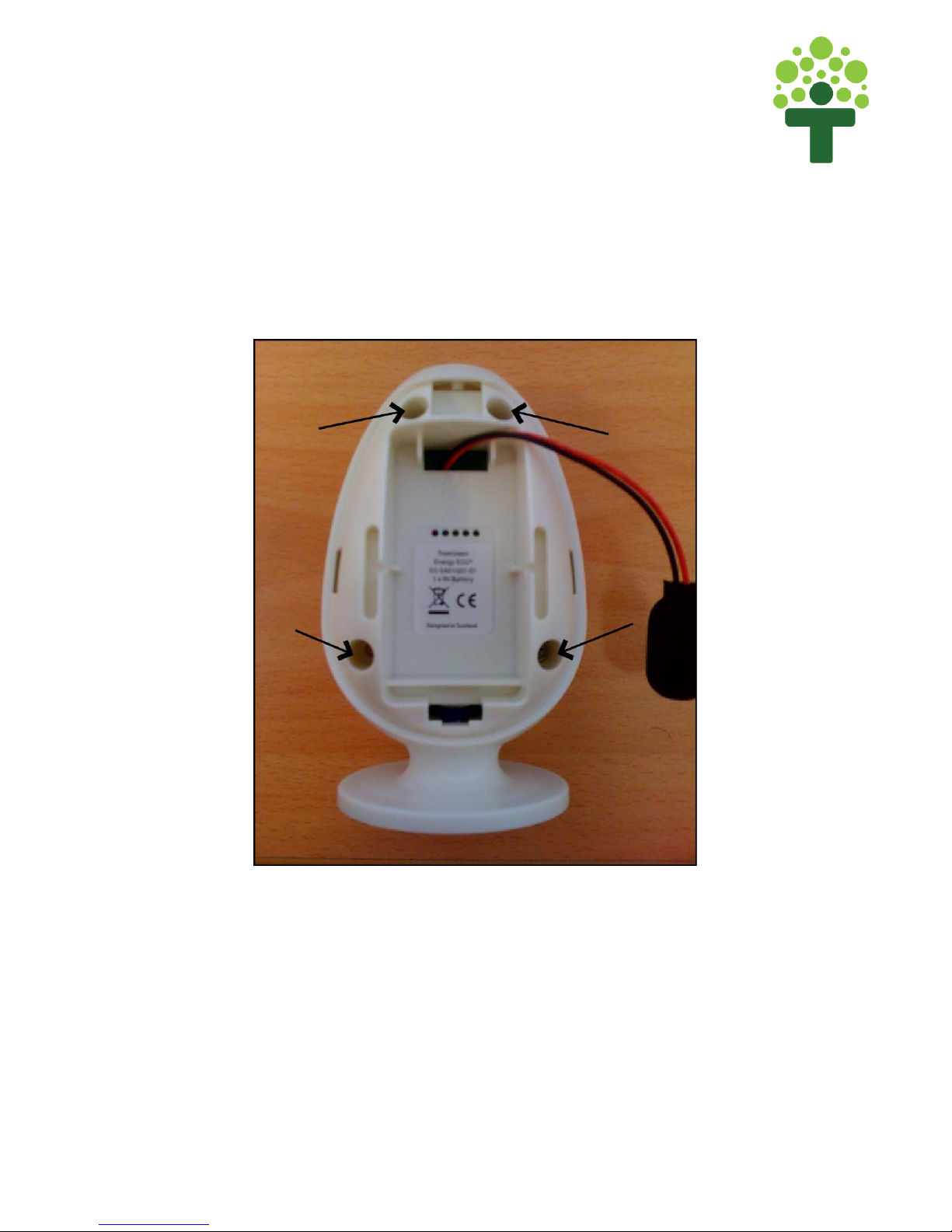
Step 6 : Insert Screws
Whilst holding the assembled EGG together, fasten 4 screws into the back of
the Main Base (EG-001) as shown in Figure 6a.
Figure 6a - Screw Locations

19
energyEGG Assembly Instructions
Now place the Compliance label in the recessed area on the Energy EGG as
shown in Figure 6b. The Compliance label should not obstruct the 5 pinholes.
The energyEGG is not shipped with the battery pre-installed, and as such, the
Compliance Label must be visible to the user.
Other manuals for energyEGG
1
Table of contents


