5
EN
Muse GP
minipool
2CHECKING MINIPOOL INTEGRITY
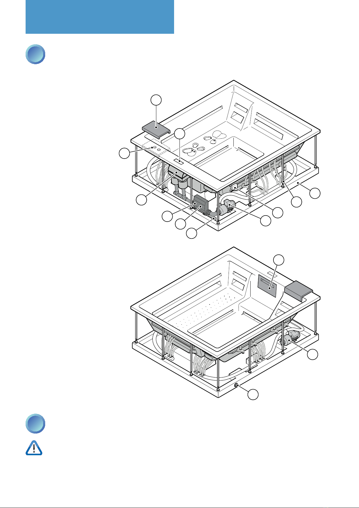
After having removed the minipool from the packing, check its integrity.
Check:
• That there is no visible structural damage;
• That there are no cracks in the surface of the minipool or in the outer covering (cracks due to incorrect transport
or support are not covered by the warranty);
• The correct position of the sleeves and pipes;
• That any ties are not loosened.
If you notice any anomalies, do not proceed with the installation but rather promptly contact the Manufacturer.
Preliminary operations
1PREPARATIONS AND CHOICE
OF POSITION
The pre-installation sheet supplied at the time
of purchase provides all the information neces-
sary for a correct preparation of the installation
environments.
Before installing the minipool, check that everything
has been prepared. Find below a quick checklist, for
complete information always refer to the pre-installation
sheet.
Check that:
• A platform or a recess (in the case of recessed installa-
tions) of reinforced concrete, with a minimum thickness
of10cm,hasbeencreated,perfectlyatandsuitable
for supporting the weight of the minipool and the
people within.
• Ø15 cm vents have been installed to ensure proper
ventilation of the technical compartment.
• Drainage grating around the perimeter has been
installed to help preserve the equipment and the
structure (even for indoor installations);
• Non-slipooringhasbeeninstalledintheareaaround
the minipool;
• For a recessed installation, a technical inspection port
measuring at least 50 cm wide has been prepared on
all sides of the minipool;
• The connections to the electrical grid have been made
in compliance with current regulations in force in the
country of installation;
• A water softener has been installed for the water used
tolltheminipoolifthewaterhasahighdegreeof
hardness;
• For outdoor recessed versions, the walls have been
insulated to protect against the cold.
More information
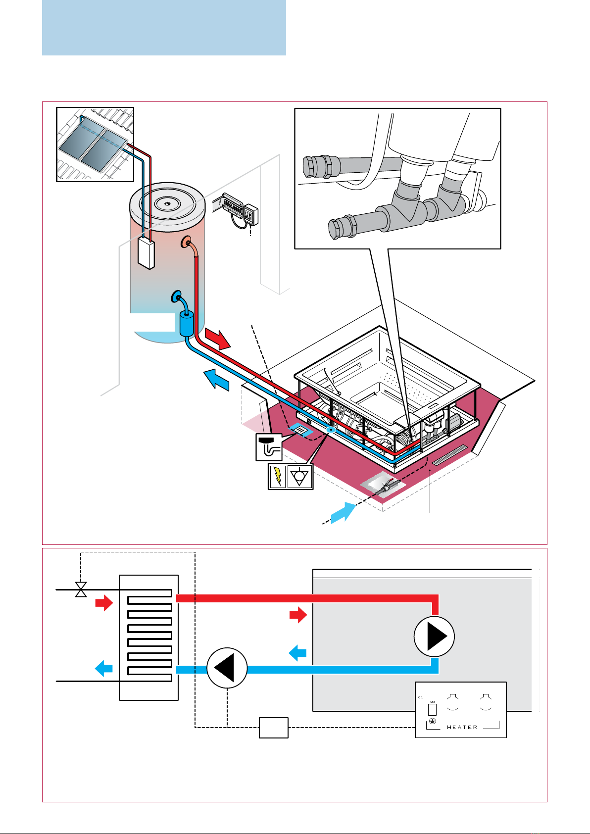
OUTDOOR INSTALLATION
Preparations:
To run the electric cables from the main electrical panel
to the minipool underground ducts must be used and
adequately protected against freezing by using insula-
tion. It is also recommended to add drainage points in
them to prevent standing water.
Choice of position: take into account the proximity of
trees or hedges, and note that debris (e.g., leaves) can
cause damage to the equipment over time that is not
covered by warranty and make maintenance more ex-
pensive and frequent. It is also recommended to always
installooringaroundtheminipool,possiblyanti-slip.
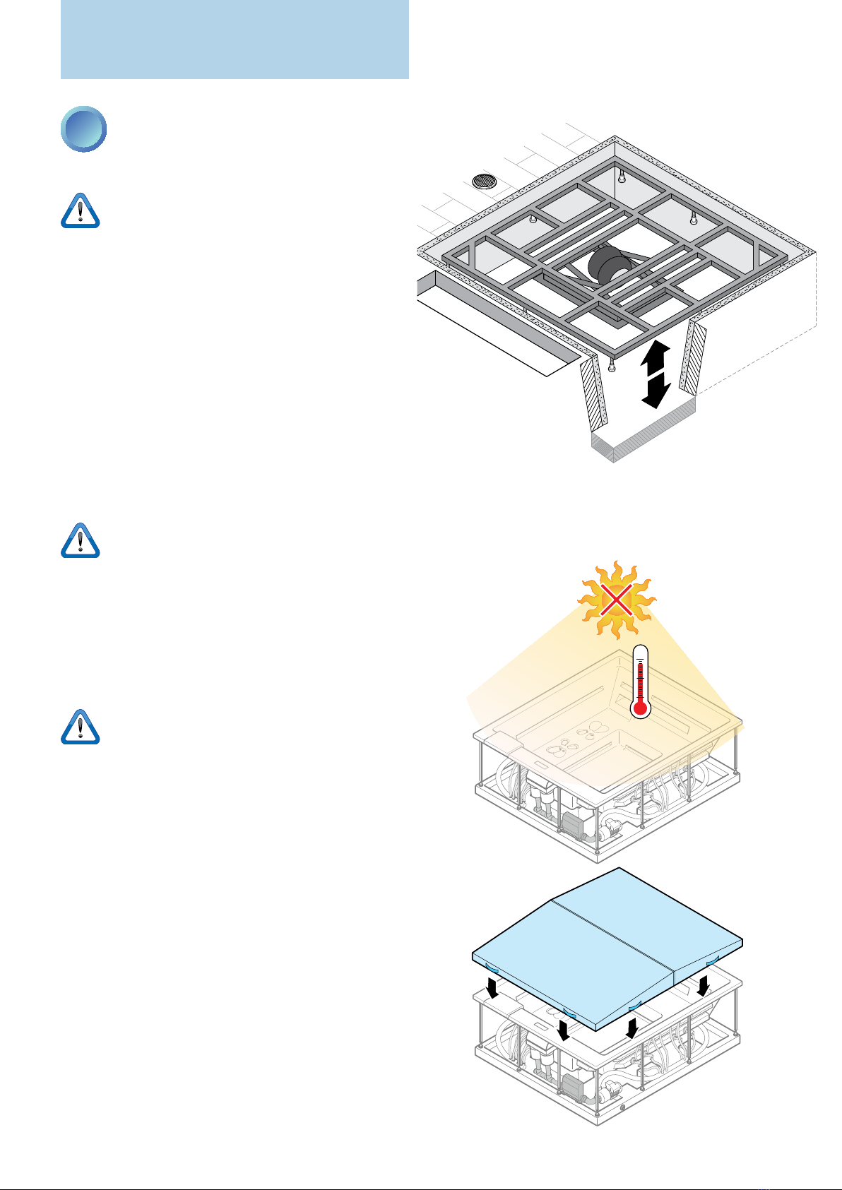
INDOOR INSTALLATION
Preparations: in the area used to access the minipool
itisrecommendedtoinstallanti-slipooring.
The evaporation of water in the minipool in the pres-
ence of high internal temperatures can generate very
high levels of humidity in the environment.
To avoid this problem, provide good natural or forced
ventilation in the installation environment and, if nec-
essary,adehumidicationsystem.Damagecausedby
this phenomenon is not covered by the manufacturer
warranty.
Choice of position: Always take into account the size
of the minipool: narrow passages, doors and steps can
be an obstacle to its transport to the desired place.