treesse Zen Pro User manual

Zen Pro
minipool
Installation manual

The installation of this minipool is simple and immediate, however we advise you to read
this manual carefully before installing it.
The Treesse team is always available for any information or request for assistance that
may be required during installation.
GRUPPO TRE S s.p.a.
Telephone +39 0761 527242
Fax +39 0761 527223
Email [email protected]
Good luck with your work!

Contents
Safety instructions __________________________________________4
EXPLANATION OF PICTOGRAMS _________________________________________________________________4
Preliminary operations ______________________________________5
1PREPARATIONS AND CHOICE OF POSITION _________________________________________ 5
2CHECKING MINIPOOL INTEGRITY __________________________________________________ 5
OUTDOOR INSTALLATION__________________________________________________________________5
INDOOR INSTALLATION ____________________________________________________________________5
Transport and position ______________________________________6
1MOVING _________________________________________________________________________ 6
2POSITIONING_____________________________________________________________________ 7
TEMPORARY POSITIONING _________________________________________________________________7
POSITIONING IN THE PLANNED LOCATION__________________________________________________7
Preliminary operations ______________________________________8
3PREPARATION OF THE SAND FILTER ________________________________________________ 8
HOW TO FILL THE SAND FILTER _____________________________________________________________8
WHAT IS THE SAND FILTER?_________________________________________________________________8
Installation _________________________________________________10
1DESCRIPTION OF MAIN COMPONENTS _____________________________________________ 10
2QUALIFICATIONS OF THE INSTALLER _______________________________________________ 10
3CONNECTIONS REQUIRED_________________________________________________________ 11
4PLUMBING CONNECTIONS ________________________________________________________ 13
CHARACTERISTICS OF THE WATER SUPPLY___________________________________________________13
TAP WATER AND WELL WATER ______________________________________________________________13
WATER HARDNESS_________________________________________________________________________13
WATER ALKALINITY ________________________________________________________________________13
5ELECTRICAL CONNECTIONS _______________________________________________________ 15
SAFETY ZONE _____________________________________________________________________________16
TESTING AFTER INSTALLATION _____________________________________________________________16
First run____________________________________________________17
1FILLING THE MINIPOOL____________________________________________________________ 17
AUTOMATIC FILLING USING THE KEYPAD ____________________________________________________17
MAINTAINING THE WATER LEVEL IN THE MINIPOOL __________________________________________17
2FIRST RUN ________________________________________________________________________ 18
3PARTIAL MINIPOOL EMPTY TEST____________________________________________________ 20
Alarms _____________________________________________________22
Troubleshooting ____________________________________________23
Decorative panels___________________________________________24
Covering ___________________________________________________25
4
Zen Pro minipool
EN
Safety instructions
Read this guide carefully before installing
the appliance, and conserve this booklet
with care for any future consultation of users.
If you do not understanding something,
contact the manufacturer for an explanation.
Installation must be carried out by
qualied personnel in compliance with
local regulations and national provisions
regarding civil and industrial systems.
Before making electrical and plumbing
connections to the equipment, the installer
must receive the declaration of conformity of
the building's systems from the user. Without
such document, the Manufacturer cannot be
held responsible for damage to the systems or
premises where the minipool will be installed.
Comply with regulations, instructions
and measurements on the "Pre-
installation technical sheet".
Unauthorised actions, tampering or
modications that do not follow the
information provided in this manual can cause
damages, injuries or fatal accidents and null
and void the warranty.
During the installation of the minipool,
do not place objects inside it, even
temporarily: they may fall down the drain
When installing the minipool, always
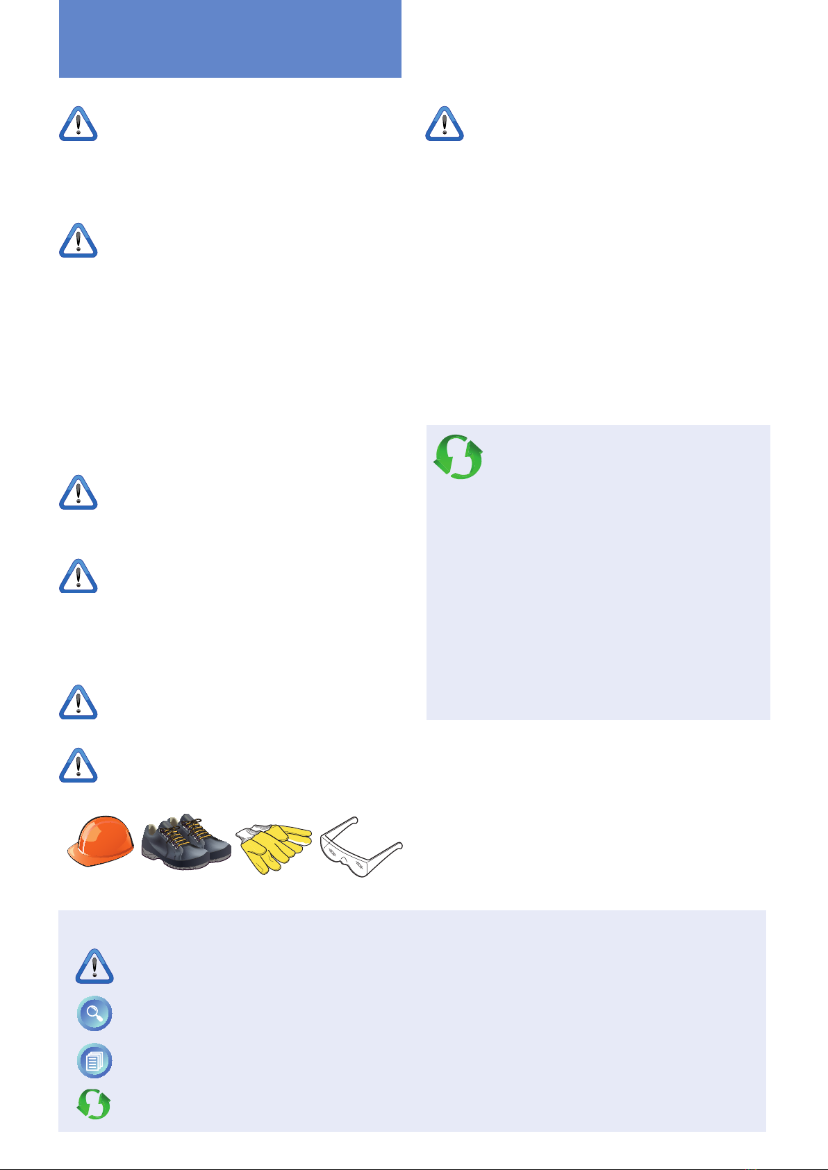
use personal protective equipment
(e.g., gloves, safety shoes, etc.)
Persons not involved with appliance
installation may not pass through or
occupy the work area during appliance
assembly.
EXPLANATION OF PICTOGRAMS
Danger! Situation presenting immediate danger, or a hazardous situation that could cause injury or
death.
More info: helps the installer understand a topic better
The pictogram refers to text in another document
Ecological notes for respecting the environment
Ecological notes
Given their potential danger, the packaging
materials must be kept out of reach of
children and animals, and correctly disposed
of in compliance with local regulations.
Treesse invites you to protect the environment
by disposing of the material in recycling bins.

5
Zen Pro minipool
EN
2CHECKING MINIPOOL INTEGRITY
After having removed the minipool from the packing, check its integrity.
Check:
• That there is no visible structural damage.
• That there are no cracks in the surface of the minipool or in the outer covering (cracks due to incorrect transport
or support are not covered by the warranty).
• The correct position of the sleeves and pipes.
• That any ties are not loosened.
If you notice any anomalies, do not proceed with the installation but rather promptly contact the Manufacturer.
Preliminary operations
1PREPARATIONS AND CHOICE
OF POSITION
The pre-installation sheet supplied at the time
of purchase provides all the information
necessary for a correct preparation of the
installation environments.
Before installing the minipool, check that everything
has been prepared. Find below a quick checklist, for
complete information always refer to the pre-installation
sheet.
Check that:
• A platform or a recess (in the case of recessed
installations) of reinforced concrete, with a minimum
thickness of 10 cm, has been created, perfectly at and
suitable for supporting the weight of the minipool and
the people within.
• Ø15 cm vents have been installed to ensure proper
ventilation of the technical compartment
• Drainage grating around the perimeter has been
installed to help preserve the equipment and the
structure (even for indoor installations).
• Non-slip ooring has been installed in the area around
the minipool.
• For a recessed installation, a technical inspection port
measuring at least 50 cm wide has been prepared on
all sides of the minipool.
• The connections to the water supply and electrical grid
have been made in compliance with current regulations
in force in the country of installation.
• A drain, a gate valve (to shut off the supply water) and
drain valves have been installed (to empty the minipool
at the end of the season).
• A water softener has been installed (upstream of the
minipool) if the water has a high degree of hardness.
• For outdoor recessed versions, the walls have been
insulated to protect against the cold.
More information
OUTDOOR INSTALLATION
Preparations: in cold areas, to avoid possible damage
due to freezing, it is recommended to provide valves
for the total drainage of the pipes, to be positioned
at their lowest point.
To run the pipes and electric cables from the main
electrical panel to the minipool underground ducts
must be used and adequately protected against
freezing by using insulation. It is also recommended to
add drainage points in them to prevent standing water.
Choice of position: take into account the proximity
of trees or hedges, and note that debris (e.g., leaves)
can cause damage to the equipment over time that is
not covered by warranty and make maintenance more
expensive and frequent. It is also recommended to
always install ooring around the minipool, possibly
anti-slip.
INDOOR INSTALLATION
Preparations: in the area used to access the minipool
it is recommended to install anti-slip ooring. The
evaporation of water in the minipool in the presence
of high internal temperatures can generate very high
levels of humidity in the environment.
To avoid this problem, provide good natural or forced
ventilation in the installation environment and, if
necessary, a dehumidication system. Damage caused
by this phenomenon is not covered by the manufacturer
warranty.
Choice of position: Always take into account the size
of the minipool: narrow passages, doors and steps can
be an obstacle to its transport to the desired place.

6
Zen Pro minipool
EN
8x
Transport and position
1MOVING
To move the minipool to the place of installation a
suitable lifting device (e.g., pallet jack) is required. As an
alternative, provide for the availability of eight people.
If the installation is indoor, before moving the minipool
make sure that it can easily pass through the doors and
hallways to reach the desired place of installation.
Movement must be carried out using personal
protective equipment (e.g., gloves, safety shoes,
etc.) and taking all the necessary safety precautions
for those involved and to not damage the minipool.
During transport, lift the minipool by holding it
exclusively by the edge and NEVER by holding the
plumbing lines or operational parts (e.g., pumps, etc.).
During movement, the surrounding area must be
kept free of persons not involved in the operation,
animals or objects (e.g., packaging, etc.) that
could get in the way.
7
Zen Pro minipool
EN
Transport and position
2POSITIONING
TEMPORARY POSITIONING
The installation of the minipool should be done
immediately upon receipt.
In any case, once unpacked, if it is necessary to
temporarily place it on a surface awaiting the installation,
it will be necessary to place level concrete slabs having
a minimum thickness of 5 cm under the entire bottom
of the minipool.
Since the temporary base may shift, it is recommended
to leave the minipool in that position for the shortest
possible time.
POSITIONING IN THE PLANNED LOCATION
In case of installation above ground (freestanding),
place the minipool in the installation environment
(outdoor or indoor) and verify its perfect atness, essential
for proper operation.
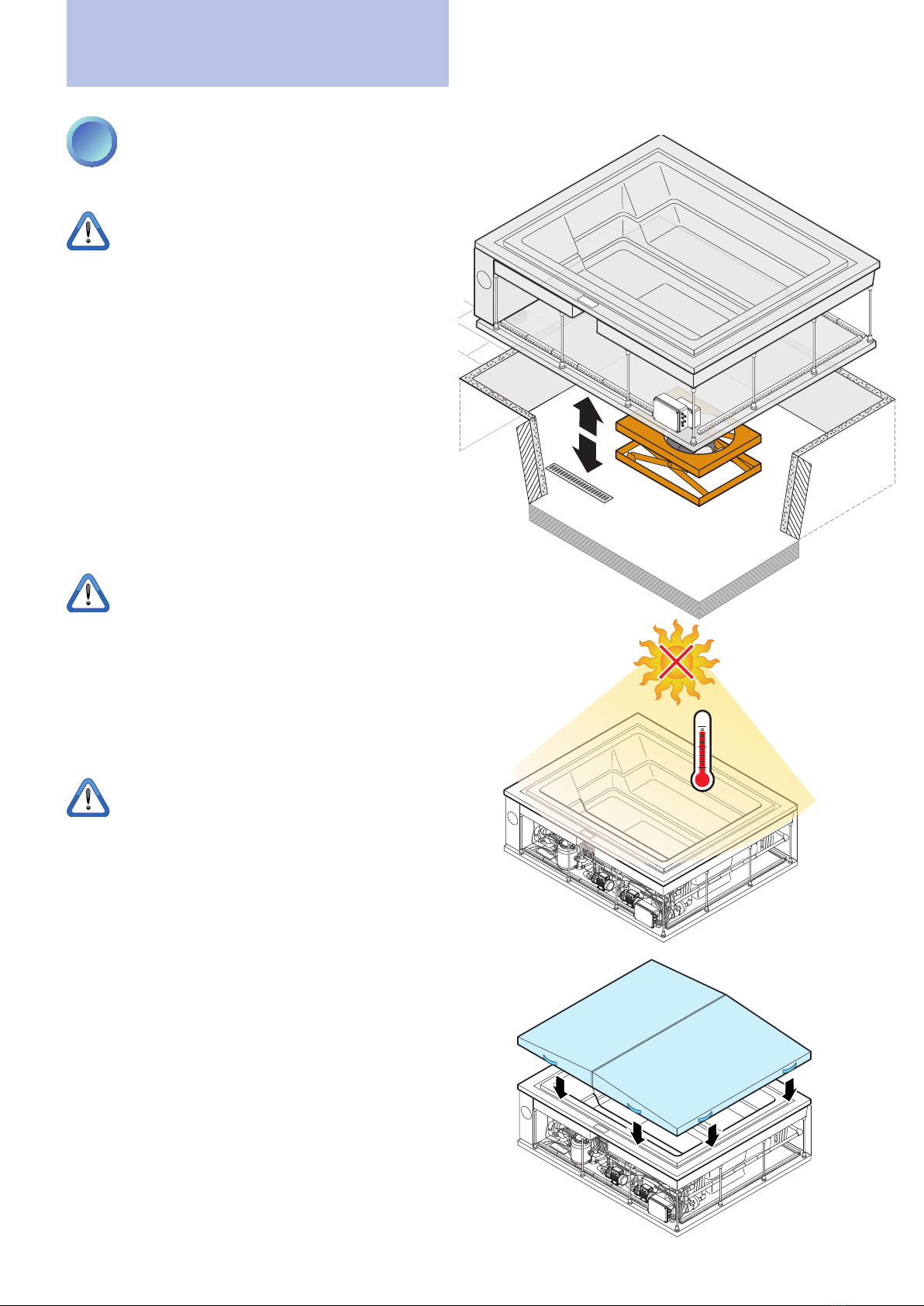
For a recessed installation, lower the minipool into the
prepared space.
If it was not possible to provide a technical
inspection port on all sides of the minipool, a
pneumatic lift is available (OPTIONAL - to be
requested from the Manufacturer) in order to simplify
future maintenance operations. It is recommended to
provide a removable inspection hatch "A" positioned on
the side where the minipool components are situated.
After positioning the minipool in its prepared space and
after having connected the lift, test it.
Do not leave the empty minipool in DIRECT
SUNLIGHT. The surface temperature could rise
above 80°C resulting in serious damage, including
cavitation and the deformation of the surface and
components. Damage caused by direct exposure to
sunlight is not covered by the warranty.
In such conditions place a cover (xed or mobile) to
protect the minipool.
80°C
176°F
80°C
176°F
OPTIONAL
Optional lift with removable inspection hatch "A"
positioned on the side where the components of the
minipool are situated.

8
Zen Pro minipool
EN
Preliminary operations
3PREPARATION OF THE SAND
FILTER
The minipools have an empty lter and so it has to be
lled.
HOW TO FILL THE SAND FILTER
To ll the lter use the sand supplied and follow the
instructions provided on the following page.
If the sand has to be replaced it must be similar to the
kind supplied (for food use). If necessary contact the
Manufacturer for more details.
When lling is complete, reposition the lter in its
compartment and check that the connections are
correct and that there are no leaks.
LEGEND FIGURE 1 ON THE NEXT PAGE:
A) incoming water
B) outgoing water
C) drain
More information
WHAT IS THE SAND FILTER?
The sand lter is an effective minipool lter connected
to the recirculation pump's feed line. It consists of a
large container that is two-thirds lled with quartz sand.
It retains the dirt and the suspended particles present
in the water.

9
Zen Pro minipool
EN
Preliminary operations
Caution! Do not inhale
Carefully clean and verify
that the gaskets are still in
place
INTERIOR - top view
Caution!
Make sure that the six
internal lters are correctly
positioned and secured
(see gure).
C
A
ø 1-3mm
ø 1-3mm
23 cm 7 cm
13B
3A
3A
23
54 6
ø 0,5-1mm
7
10
8
10A
10A
11A
10B
11B
11C
11 12
13
ø 0,5-1mm
B
9

10
Zen Pro minipool
EN
1
8
2
11
3
10
95
4
67
12
Installation
1DESCRIPTION OF MAIN COMPONENTS
1 Control Panel
2 Compensation tank
3 Sand lter
4 Electric pump 1
5 Electric pump 2 (optional)
6 Electronic control units
7 2 x Blowers (of which 1 is optional)
8 Heater
9 Drain valve
10 Ozone
11 Compensation tank inspection
12 Overow edge
2QUALIFICATIONS OF THE INSTALLER
Before installation it is recommended to carefully read the safety warnings at the beginning of this manual
and to always operate in perfect physical and mental condition.
The installer, qualied and authorised by the Manufacturer, must carry out the operations based on his or her
professional qualications. Any activities for which he or she is not qualied (e.g., plumbing or electrical connections)
must be performed by specic and qualied professionals so as not to risk their own safety and that of others who
interact with the equipment.

11
Zen Pro minipool
EN
Installation
3CONNECTIONS REQUIRED
To be used, the minipool requires only
two connections:
1plumbing connections
(incoming and outgoing water)
2electrical connection
(power supply)
3electrical and plumbing connection
to an exchanger (optional - if present)
- see following page.
The following pages will provide detailed
explanations of how to perform these
preparations.
EXAMPLES OF OUTDOOR/INDOOR
MINIPOOL INSTALLATION.
IN
IN
ø40
ø40
Electrical connection
Electrical connection
Drain
Room for
the electrical
connections
Room for
the electrical
connections
Drain
Water supply
Loading
supply
Technical
inspection
port

12
Zen Pro minipool
EN
Installation
CONNECTION TO AN OPTIONAL EXTERNAL EXCHANGER (NOT SUPPLIED)
IN
OUT
IN
ø40
IN
OUT
IN
OUT
Electrical connection
Exchanger
(not supplied)
Circulator
(not supplied)
Room for
the electrical
connections
Drain
Loading
supply
Technical
inspection
port
IN: incoming
hot domestic
water
OUT: outgoing cold
water
230V
C
S
P
in
out
PR
TC
EV
BS
P2
BL 1
BL2
HTR
Cromo
230V~
EVc
EVs
EVclv
+
-
230V heater/exchanger control cable
BS: water coming from the overow edge
C: switch (recommended)
OUT: outgoing cold water
P: circulator (not supplied)
PR: recirculation pump
S: exchanger (not supplied)
TC: minipool compensation tank

13
Zen Pro minipool
EN
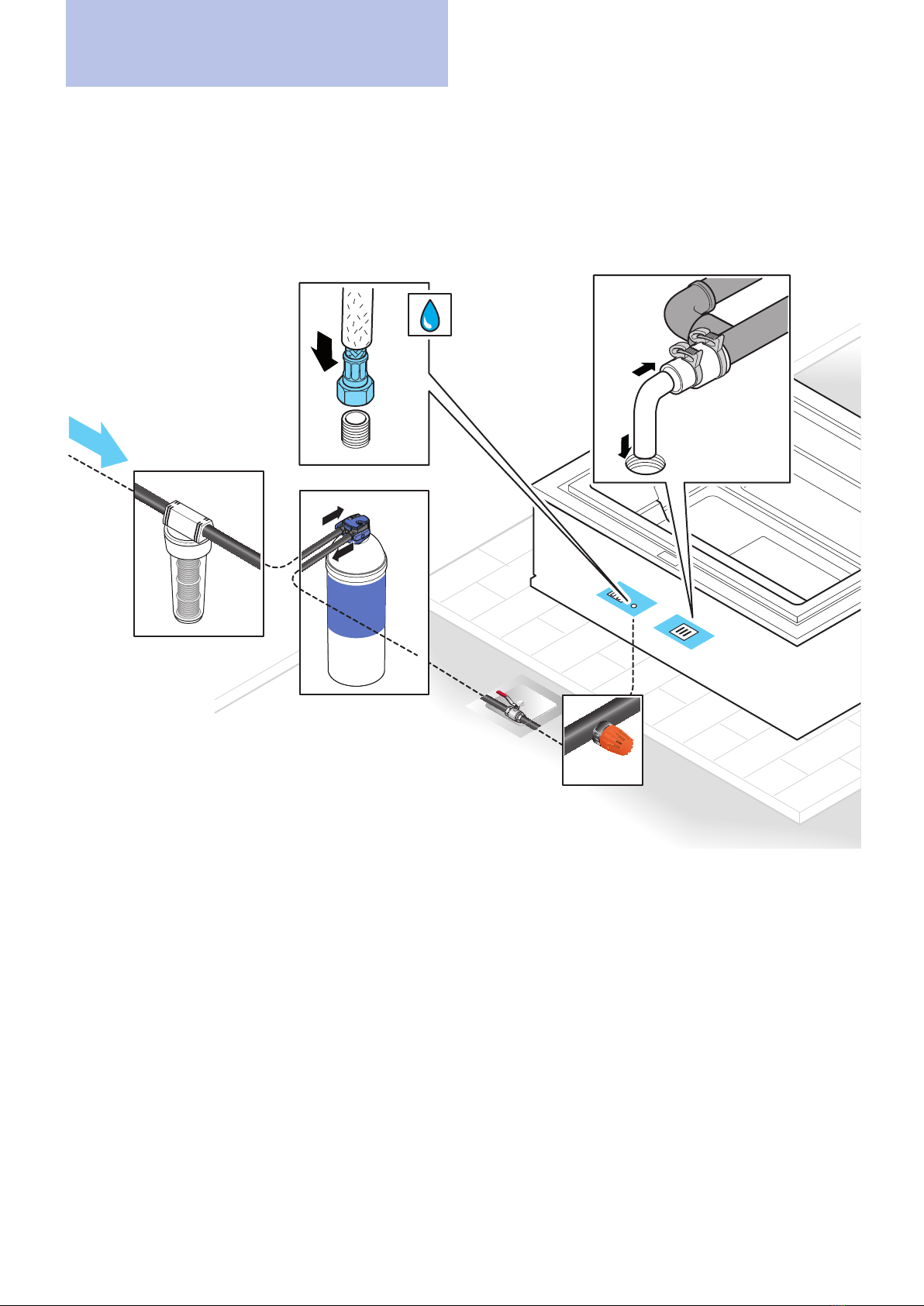
4PLUMBING CONNECTIONS
All water connection operations must be
performed after making sure that the minipool's
water supply valve is CLOSED.
The connection must be made by an experienced,
qualied plumber.
It is recommended to use ONLY tap water. If this
is not possible refer to the "more information"
section to the side.
The plumbing connection must be:
• Dedicated exclusively to the minipool (it is not possible
to connect other equipment to the same connection).
• Made with hoses and connectors that are new and
never used.
CHARACTERISTICS OF THE WATER SUPPLY
The optimal values for the water supply are as follows:
• Hardness between 7ºf and 14ºF (fresh water) - 200 to
400 mg/l (ppm).
• Total alkalinity (TA) between 80 and 125 mg/l (8-12.5°F).
• pH between 7.4 and 7.8.
• minimum inlet pressure: 150,000 Pa (1.5 bar)
• minimum inlet pressure: 300,000 Pa (3 bar)
• Water suitable for human consumption.
Make sure that during the pre-installation all the
characteristics of the water supply have been met (see
"Pre-Installation Sheet" on p. 9).
More information
WATER HARDNESS
Water hardness (TH) is determined by the total content
of calcium and magnesium present in the water, coming
from their soluble salts.
Water classication:
........up to 7ºf = Very soft water
From 7ºf to 14ºf = Soft water
From 14ºf to 22ºf = Slightly hard water
From 22ºf to 32ºf = Fairly hard water
From 32ºf to 54ºf = Hard water
........more than 54ºf = Very hard water
(1°f = 10 mg calcium carbonate per litre of water)
WATER ALKALINITY
Alkalinity (CAT) represents the concentration of
bicarbonate ions present in the water. It is expressed
as mg/L of calcium carbonate or in French degrees (°F).
Ideal values of alkalinity range between 80 mg/L and
125 mg/L (8°F-12.5°F). Values outside of this range
can more easily cause variations of the pH. Instead,
alkalinity within the range noted makes it possible
to "buffer" the pH value, resulting in fewer abrupt
variations.
WATER PH
What is pH?
The pH is a chemical parameter that gives an idea of
the acidity or basicity of the water. It can assume values
between 0 and 14. By denition water is considered
neutral if its pH is equal to 7. It is acidic if the pH is lower
than 7 and basic if the pH is greater than 7. Disinfectants
have an ideal pH at which they are most effective. In
the case of heated water treated with bromine products
it is recommended to keep the pH value in the range
from 7.4 to 7.8 using chemical correctors as needed
if the pH is higher or lower to bring the the pH value
back to the recommended interval.
acqua acida acqua alcalina
pH acido pH neutro pH basico
0 1 2 3 4 5 6 7 8 9 10 11 12 13 14
More information
TAP WATER AND WELL WATER
To ensure maximum hygiene and durability of the
minipool it is essential to pay close attention to the
quality of the water that will be used to ll it. It is
important that the water used be drinkable. It is always
advisable not to use well water because it may be very
hard, rich in metals like iron and manganese, and have
bacterial loads. Tap water is recommended. In the case
of very hard or ferrous water it is always recommended to
install softening and iron removal systems upstream. The
company cannot be held responsible for issues related
to the use of non-drinkable water or lack of installation
of such systems. The plumber is responsible for choosing
the type of components to be used and the verication
of compliance with the purity and potability parameters
of the water supply.
Installation
14
Zen Pro minipool
EN
Installation
1/2”
IN
OUT
IN
ø40
Filters*: retain
impurities and oxides
(indispensable if the
water comes from a
well)
Softener*: reduces
the water hardness to
optimal values
Gate valve*: shuts
off the water ow
Drain Valve*: useful for
emptying the pipes
during maintenance
or at the end of the
season.
Connection to the minipool using the 1/2 inch female hose
provided.
If the minipool is installed outdoors provide an adequate thermal
insulation of the pipes. It is the plumber's responsibility to choose
the type of materials to be used.
Connect the drain of the oor minipool. The
plumber is responsible for the choice and type
of materials to be used and the verication of
compliance with anti-pollution standards.
* The images are purely indicative: the model and type must be chosen by the plumber based on the characteristics of the water and the current
system.
EXAMPLE OF PRE-INSTALLATION PLUMBING FOR A MINIPOOL
15
Zen Pro minipool
EN
Installation
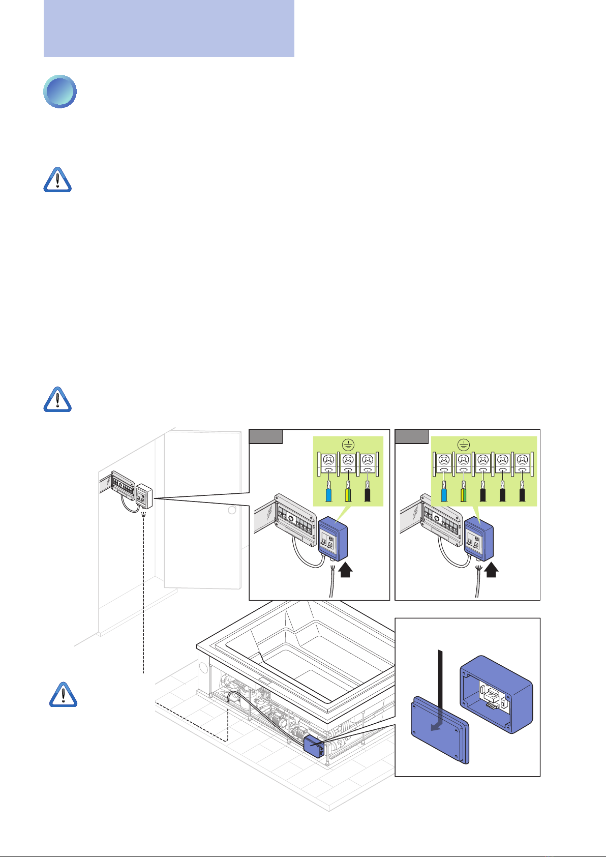
5ELECTRICAL CONNECTIONS
The Treesse minipools are built in compliance with European laws (EN 60 335-2-60) and are tested during production
to ensure the safety of the installer and user.
The connection must be made by an experienced, qualied electrician.
All electrical connections must be made only after disconnecting the electricity in the work area.
The electrical connection must be:
• Performed in a xed and permanent manner, without intermediate splices, in accordance with regulations of the
country of installation.
• Sufcient for the current absorbed by the bathtub (see technical specications).
• Provided with a functioning ground as per current regulations.
• Protected against splashing water, then placed in a dedicated room, closed and sheltered from the weather.
• Controlled by a multi-pole switch with a contact gap of at least 3 mm and a breaking capacity equal to 60A (or in
any case adequate for the absorption of the bathtub).
• Controlled by a differential switch no larger than 30mA.
The control unit's power supply cable must be of the H05 type with three wires (single-phase 220V) or ve wires
(three-phase 380V) whose gauges are adequate for the absorption of the minipool (see "Pre-installation sheet"). Its
size depends on the absorbed current and the distance of the minipool from the main electrical cabinet.
In addition, if the minipool is installed outdoors, the power cord from the main electrical panel to the minipool must
pass through an underground duct, without splices and adequately protected against freezing.
The Manufacturer is not responsible for connections made in a way that does not comply with local codes, the
specications in this manual or tampering with any electrical component of the minipool.
NLNL1 L2 L3
220V~ 380V~
When the
connections
have been
made, verify the proper
operation of the
differential switch by
pressing the TEST key.
ELECTRICAL DIAGRAM

16
Zen Pro minipool
EN
Installation
SAFETY ZONE
min.
60 cm min.
60 cm
min.
60 cm
min.
60 cm
min.
60 cm
MIN. 230 cm
MIN. 230 cm
Local regulations prohibit any electrical installation (plug sockets, switches, lamps, etc.) in the area surrounding
the minipool for a distance of at least 60 cm and a height of 230 cm.
MAKE SURE THAT... √
The minipool is level and stable.
The sand lter is lled and properly connected to the pipes.
The water connections have been made properly in accordance with local and national codes and that
they can guarantee a perfect seal (verication to be carried out after lling the minipool).
Electrical connections are made correctly in accordance with local and national codes and that the cables
are not damaged, crushed or abnormally bent.
The minipool's drainage valves are closed.
The water supply gate valve has been opened.
Tools, documents or other items were not left under the minipool or in the recess.
TESTING AFTER INSTALLATION
6

17
Zen Pro minipool
EN
First run
This cycle will be repeated many times until both the
compensation tank and bathtub are lled. At this stage
and until lling is completed, no other functions of the
minipool - except chromatherapy - will be available.
During the lling phase, if the times for reaching the
minimum (90 min) and maximum (60 min) levels in the
overow tank are not met, alarms "AL1" (minimum level)
and "AL2 "(maximum level) will be triggered, stopping
all operation.
In this case, you will have to disconnect the power and
restore it after about 30 seconds using the product's main
power switch and check the reason for this anomaly (leaky
pipes, obstructed supply valves, insufcient pressure).
During the use of the minipool the system automati-
cally maintains the water level ush with the edge of the
bathtub.
Automatic lling using the keypad pressing
the key activates the automatic lling of the
minipool, controlled by two level sensors.
26∞ OK
More information
MAINTAINING THE WATER LEVEL IN THE
MINIPOOL
When the minipool is completely lled a maximum
sensor (SL2) and a minimum sensor (SL1) continuously
monitor the water level inside the compensation tank.
SL1 (minimum sensor) = 0, the sensor does NOT detect
water
SL1 (minimum sensor) = 1, the sensor detects water
SL2 (maximum sensor) = 0, the sensor does NOT detect
water
SL2 (maximum sensor) = 1, the sensor detects water
If the lack of water is minimal (e.g., evaporation or a
person gets out):
• The minimum sensor still detects water (SL1 = 1).
• The maximum sensor does not detect water (SL2 = 0).
• activates automatic lling until conditions are
restored and for a maximum of 60 minutes.
If the lack of water is considerable (e.g., two or more
people get out of the minipool):
• Both the minimum and maximum sensors do not
detect water (SL1 = 0, SL2 = 0).
• The recirculation pump moves the water from
the compensation tank to the minipool.
• The minimum sensor detects water (SL1 = 1, SL2 = 0).
• activates automatic lling until conditions are
restored and for a maximum of 60 minutes.
1FILLING THE MINIPOOL
Perform a preliminary cleaning of the minipool using a
bit of water and a mild detergent.
Do not use cloths or cleaners that are abrasive, aggressive
or that contain solvents because they could irreparably
damage the surface of the minipool.
Do not start any operation until the minipool has
been completely lled, otherwise the minipool
could be damaged.
Before lling, once again check the quality of the water
supply. This is very important for the well-being of the
users and for the long life of the minipool.
For more information see chapter “Characteristics
of the water supply” on page 13.
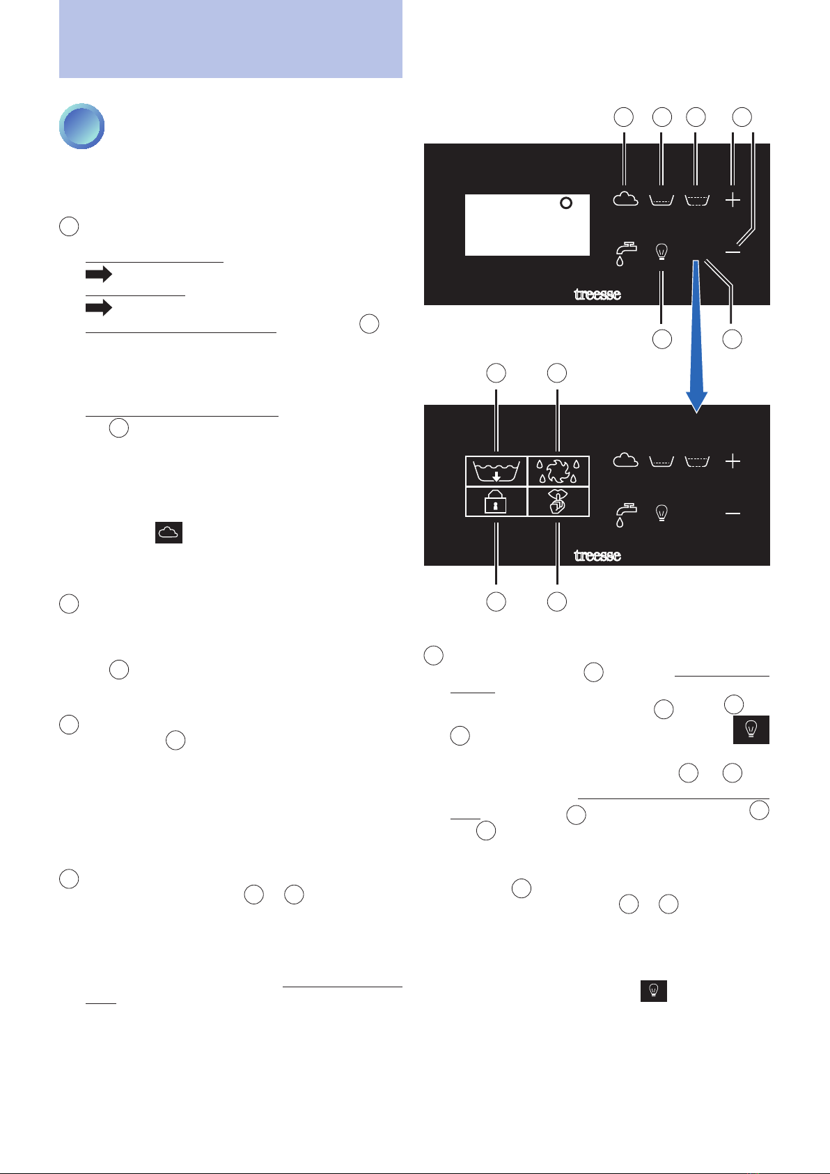
AUTOMATIC FILLING USING THE KEYPAD
Once the pool is powered, the display will show the word
"treesse" and after a few seconds the display will show
the current ambient temperature, and the various sym-
bols on the keypad will be illuminated with white light.
Press the key on the keypad to activate lling: lling
in progress is indicated by the blue icon.
First the compensation tank is lled, and then - once
the water has reached the maximum level inside the
tank - the bathtub is lled through a recirculation pump,
passing through the sand lter and the heater.
18
Zen Pro minipool
EN
2FIRST RUN
With the bathtub full, recirculation active and ozone
active, start in sequence all the functions of the bathtub
in the presence of the owner to verify proper operation:
1BLOWER
The minipool can be equipped with:
A single blower motor (standard)
activates the nozzles on the bottom.
A second motor (optional)
activates the nozzles on the seat.
If there is only one blower motor, pressing the 1key
starts the bottom nozzle operation (default duration
20 minutes).
The blower function on the bottom cannot be started
if the whirlpool is running.
If there are two blower motors (optional), pressing
the 1key will activate the function, alternating the
two zones (bottom nozzles + seat nozzles) with an
interval of 30 seconds and always for a maximum
duration of 20 minutes.
The blower function on the seat can be started even
if the whirlpool is running.
When the key is pressed again, the blower
function stops, the key returns to white and the
temperature is shown again on the display.
2LYMPHODRAINING CHAISE LONGUE
WHIRLPOOL (OPTIONAL)
The function can only be activated if the whirlpool jets
are present in the seat on the command side. Press
the 2key to start the function (default duration 20
minutes), press it again to stop it
3PERIMETER WHIRLPOOL (BACK AND LEGS)
Pressing the 3will activate the whirlpool function
in the two perimeter slots present in the minipool
(default duration 20 minutes). Press the key again to
stop the function. The rst time it is recommended
to leave the whirlpool in operation for at least 2-3
minutes to expel the air that may be present in the
plumbing system.
4WATER TEMPERATURE ADJUSTMENT
When one of the two keys
+
or
-
is pressed once,
the display shows the current setting (default 35°C) and
the two keys are illuminated with a strong blue light.
From the second press on, the displayed value is
increased or decreased by one degree at a time
depending on the key pressed (range from 15°C to
40°C).
After six seconds of inactivity with the keys or if
another key is pressed, the adjustment function will
end and the two keys will return to white, memorising
the new setting.
The function will activate the heater (ashing degree
character) with the objective of heating and maintaining
the water temperature at the set value (+/- 0.5°C).
First run
5CHROMATHERAPY
Pressing the light key 5activates a sequence of 16
colours that vary in an automatic sequence (default
duration two hours):
The light key
5
and the
+
and
-
keys turn blue and the display shows the
+
symbol for six seconds.
During this time you can press the +or -key
to manually select a colour that you want to remain
xed:
the light key
5
will remain blue, while the
+
and
-
keys will turn white again: at this time it is no
longer possible to change colour.
To once again manually select the colour, press the
light key 5again and select the desired colour
within six seconds with the +or -key.
Once you have selected a xed colour, to return to the
automatic sequence you must turn off and reactivate
the function.
To stop the function hold the key pressed for
about three seconds. The key will turn white again
and the temperature will reappear on the display.
The function can always be activated, even if the water
level is low.
OK
OK
3”
1
7
9
8
10
2
5
3
6
4
Submenu
page
Main page

19
Zen Pro minipool
EN
First run
6“OK”
If pressed for more than three seconds you access
a submenu page where other system functions are
available (empty, manual backwash, keypad lock,
SILENCE mode).
When accessing special functions, the "KEYPAD
LOCK" icon is always lit by default.
To scroll through the various functions, press the "+"
and "-" keys. When the icon of the desired function
lights up, press the "OK" key to activate it.
After six seconds of inactivity the display exits
the submenu and returns to showing the water
temperature.
7KEYPAD LOCK
Activation of this function will not allow the tempera-
ture set point to be changed, while the whirlpool,
blower and chromatherapy functions will remain
active.
To activate it:
APress the "OK" key 6for at least three seconds.
Bthis provides access to a submenu page.
CThe icon “KEYPAD LOCK” 9is illuminated, press
the “OK” key 6to activate it.
When the function is activated, the display will show
the word "LOCK" for six seconds and then return to
showing the water temperature.
To disable the function, press the "OK" key again for
three seconds and then press the "KEYPAD LOCK"
key 7again.
8EMPTY
The emptying of the minipool can be activated at
any time.
To activate it:
APress the "OK" key 6for at least three seconds.
Bthis provides access to a submenu page.
CUse the
+
and
-keys until the “EMPTY” 8
icon is illuminated and press the “OK” key 6to
activate it.
The display shows the icon throughout the
entire emptying operation.
Emptying lasts 120 minutes and for the entire
duration the bathtub needs to be powered to allow
it to completely drain all residual water from the
tank pipes and lter. During emptying, the blower is
automatically activated to drain the airpool system
pipes.
During emptying of the minipool, the only enabled
function is chromatherapy.
To stop the emptying test, disconnect the power
supply to the bathtub for about 30 seconds.
OK
OK
3”
1
8
7
9
10
2
5
3
6
4
Submenu
page
Main page

20
Zen Pro minipool
EN
First run
3PARTIAL MINIPOOL EMPTY TEST
The minipool can be drained at any time, without people inside the minipool.
Perform a brief test to verify that the water is correctly drained.
To activate emptying:
APress the "OK" key for at least three seconds.
Bthis provides access to a submenu page.
CPress the "EMPTY" 7key.
During emptying of the bathtub, the only enabled function is chromatherapy.
To stop the drain test, press the "EMPTY" key again.
Once the test is nished, rell by pressing the key .
9MANUAL BACKWASHING
In Treesse minipools the backwashing is automatic,
running automatically every 48 hours of use of the
minipool, but can be forced manually:
APress the "OK" key 6for at least three seconds.
Bthis provides access to a submenu page.
CUse the
+
and
-keys until the “BACKWASH”
9icon is illuminated and press the “OK” key
6to activate it.
10 SILENCE MODE (SILENT HOURS)
This function provides access to a page where the
hours of the day can be specied during which the
control enters SILENCE operating mode (silent
hours), when all the automatic activations of the
pumps and/or blowers are inhibited and only the
antifreeze safety function remains active.
More precisely:
• If an automatic function is active when the SILENCE
function is engaged, it is deactivated immediately
(except for antifreeze).
• If a user function (whirlpool or blower) is active when
the SILENCE function starts, the SILENCE function
remains suspended and will become active 10
minutes after the user function has been switched off.
• If a user function is activated by the user while the
SILENCE function is active, the latter is suspended
(and heating and ltering is re-enabled) and will be
reactivated 10 minutes after the last user function
has been switched off.
• If the temperature set point is changed during the
SILENCE function, the new value will become valid
at the end of the function.
• The CHROMATHERAPY function 5is not affected
by the SILENCE function.
• The maximum duration of the SILENCE function is
20 hours (even non-consecutive) in order to maintain
the water temperature at the set value and to ensure
ltering.
How to set the SILENCE function:
APress the "OK" 6key for at least three seconds.
Bthis provides access to a submenu page.
CUse the
+
and
-keys until the “SILENCE” 10
icon is illuminated and press the “OK” key 6to
activate it.
DWith the +or -key move to the hour boxes.
EPress the "OK" key to enable the "SILENCE" mode
schedule:
White box: silence mode disabled
Grey box: silence mode enabled (recirculation
inactive)
EXAMPLE
Silent hours highlighted in the table: silent mode acti-
vated from midnight to 7 am and from 3 pm to 4 pm
DISABLE (white boxes): silence mode disabled
ENABLE (dark boxes): silence mode enabled (recircula-
tion inactive)
0123
45
678910 11
12 13 14 15 16 17
18 19 20
DISABLE ENABLE
21 22 23
+-
After six seconds during which no key is touched the
conguration is memorised and the water temperature
is displayed again.
Table of contents
Other treesse Swimming Pool manuals


