CARVIN®SILVER SERIES ABOVE-GROUND POOL | USER MANUAL
4
INSTALLATION
Before starting the installation of your pool, make sure you have all the necessary
tools listed below. Check the contents of each of the boxes containing the parts of
the pool and make sure everything is there before starting your installation. All parts
included in the boxes are important and should all be installed. If parts are left out
from the installation, this could cause serious failure of the pool structure. Once the
installation of a swimming pool is started, it should be completed as soon as
possible.
If a part is missing or defective, please contact your CARVIN®retailer were your
purchase was made.
TOOLS
•Shovel
• Water hose
• Hammer
• Rubber mallet
• Soil Compactor (manual or mechanic)
• Linear level
•Pliers
• Vacuum cleaner
• Gardening rake
• Measuring tape
• Drill, ratchet or adjustable wrench
• Screwdriver bit #3 Phillips or Robertson
• Hexagonal socket 7/16”
•Wheelbarrow
• Punch 3/16” diameter
•Stepladder
• Vinyl covered hook, rope and tent pegs
REQUIRED MATERIAL
• Duct tape 2”
• Nails or rods 8” (number of uprights +1)
• Wall stabilizing hooks (number of uprights)
• Sand (see below quantities)
• Patio slab (equal to the # of uprights)
• Prefabricated cove sections (option)
• Under liner pool carpet
• Plywood sheet ½”, (2x) 3’ x 3’
• Cardboard 16” x 9“
• Wooden plank 2” x 4” of length equal to the radius of the pool
•CARVIN®pool parts
REQUIRED POOL EQUIPMENT
A basic circulation and ltration system MUST BE INSTALLED. This system includes
the following products by installation order:
• A skimmer
• Pool pump
• Filter
• Water return
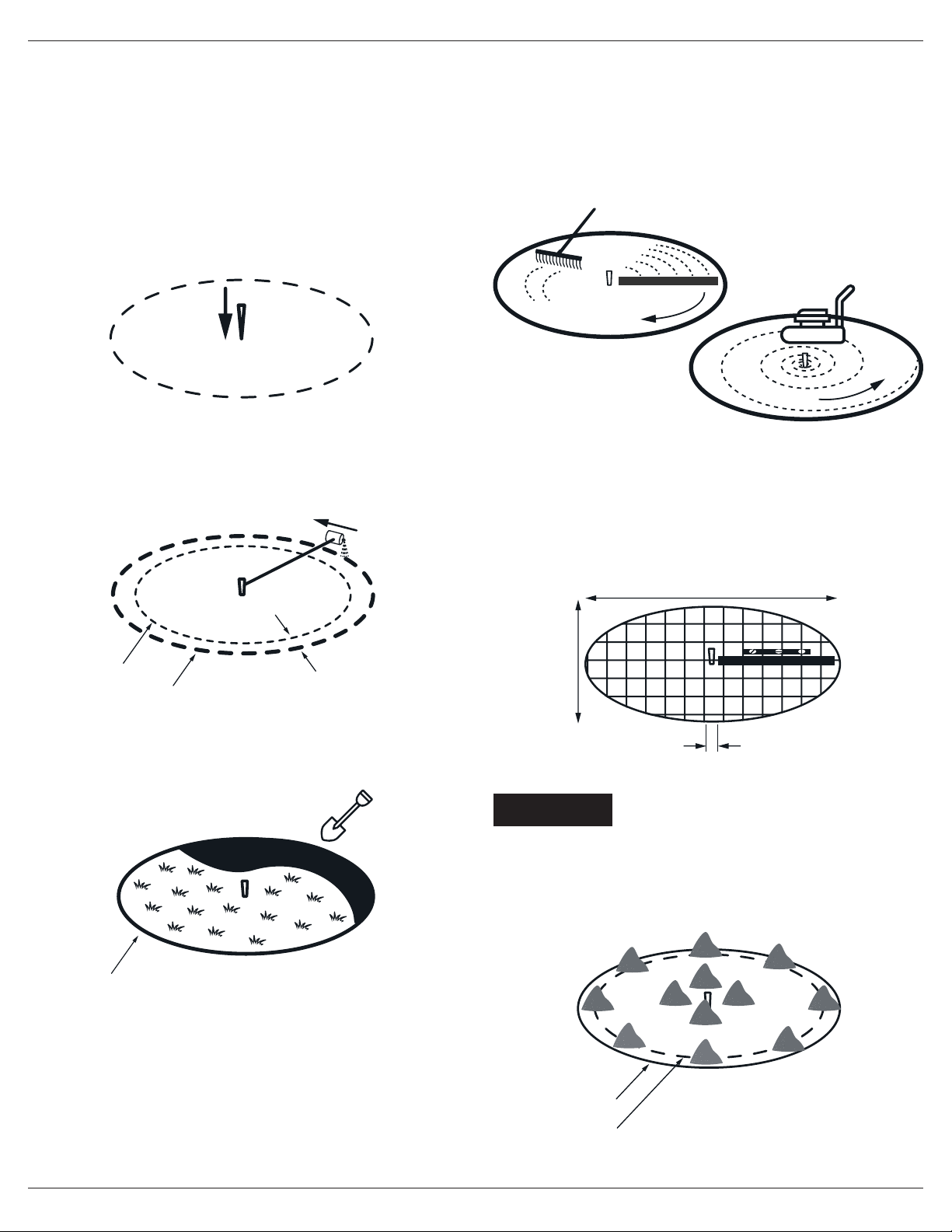
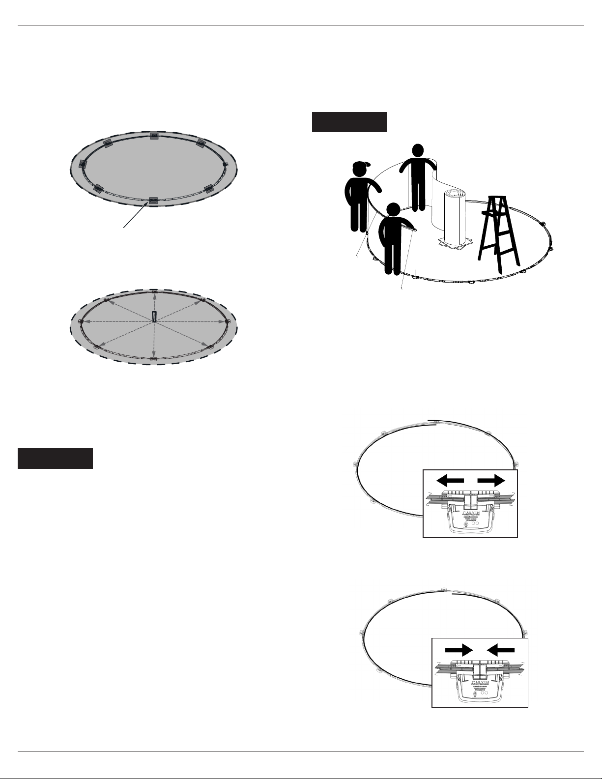
POOL LOCATION
We highly recommend you hire a certied installer recommended by your retailer
to install your pool. If you decide to install your pool yourself, we recommend it be
done by at least 3 people.
INFORMATIONS REQUIRED
FOR SWIMMING POOL INSTALLATION
POOL SIZE 12’ 15’ 18’ 21’ 24’ 27’
POOL RADIUS 6’ 7’6’’ 9’ 10’6’’ 12’ 13’6’’
FONDATION RADIUS 7’ 8’6’’ 10’ 11’6’’ 13’ 14’6’’
SAND REQUIRED
(TONS)* 1,5 2 3 3,5 4,5 5
* The material required for the foundation should be the nest rock dust possible and can be
mixed with sand.
The installation must comply with the codes of the
authority having jurisdiction and may require permits
for building, plumbing electrical, zoning etc. Check local
municipal laws and rules before starting your installa-
tion, this could inuence the location of your pool.
The Warranty of the Product will be canceled if all instal-
lation requirements and guidelines are not respected.
WARNING
WARNING One of the most important steps is to choose the ideal location for your pool.
This will determine the life expectancy of your pool.
• The ground must have a good drainage and be solid, have a positive slope
(keeping the water away from pool base), should not be on a hollow ground since
this will result in a build up of water, this could jeopardize your foundation and
damage your pool.
•The ground must be free of rocks, pebbles, tree roots, bamboo and cattails.
•Never install your pool in a place where chemicals have been spread, this could
damage the liner and rust the wall.
•Never install your pool on a concrete oor, asphalt, tarpaper, grass, wood, gravel
or clay.
•Position your pool far from trees, electric lines or cables, buildings (house, garage,
etc.). Swimmers could use them for diving and could get seriously injured.
•Never install your pool above buried electrical lines or above a septic tank.
•The pool shall be located a minimum distance of 6ft (1.83 m) from any electrical
receptacle. All 125 volt, 15 and 20 ampere receptacles located within 20’ (6.0 m)
of the pool shall be protected by a ground fault circuit interrupter (GFCI).
The 20’ (6 m) distance is measured via the shortest straight line distance the
supply cord would follow without piercing a oor, wall, ceiling, doorway, window,
or other permanent barrier.
•Do not cover the rail and the bottom of the wall with mulch. The mulch retains
moisture and could help rust the metal wall.
•Do not use foam as part of foundation; this would void the warranty.
IMPORTANT TO CONSIDER BEFORE INSTALLING
1. Follow the installation steps thoroughly without omitting anything. It can result in
serious accidents.
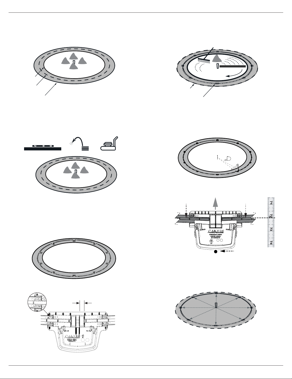
2. Your pool must be level: Your foundation base should have a maximum of ½’’ of
slope. The slope of the oor from the shallow wall towards the deep area shall
not exceed 1’ in 7’ (1: 7, 305 mm: 2134 mm) to the point of the rst slope
change. The slope of the oor from the point of the rst slope change towards the
deepest point shall not exceed 1’ in 3’ (1: 3), (305 mm: 914 mm). The slope
adjcent to the shallow area shall have a maximum slope of 1’ in 3’ (1: 3,
305 mm: 914 mm) and the slope adjacent to the side walls shall have a maximum
slope of 1’ in 1’ (1: 1, 305 mm: 305 mm). The point of the rst slope change
shall be dened as the point at which the shallow area slope exceeds 1’ in 7’
(1: 7, 305 mm: 2134 mm) and be at least 6’ (1829 mm) from the shallow end wall
of the pool.
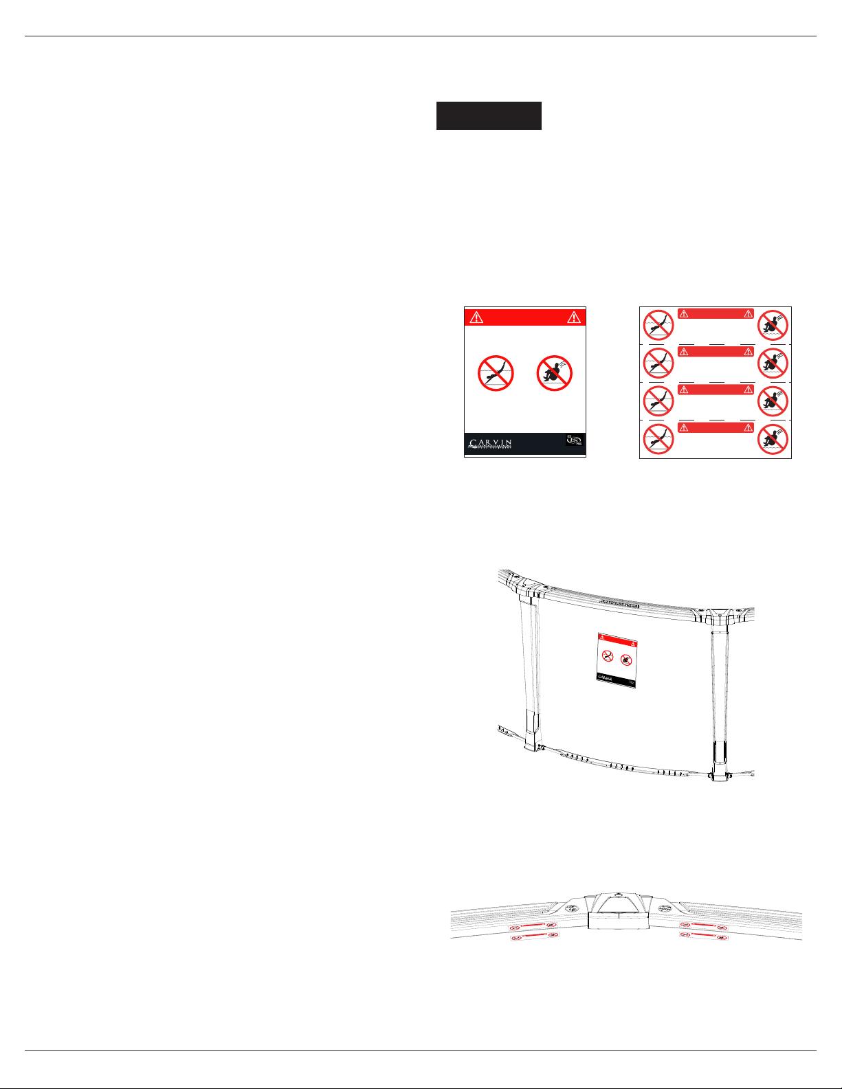
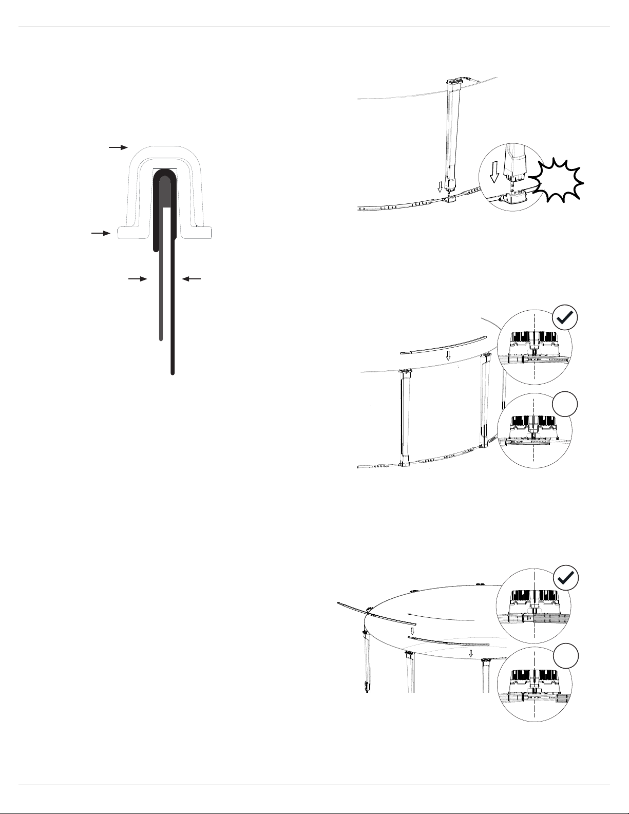
3. When closing the wall, follow the instructions in our manual using the 2 wall
brackets and all provided hardware (all holes must contain a screw).
4. The prefabricated cove sections should be well compacted. A lack of thoroughness
can result in the liner getting jammed under the rails and perforate. the ground
could deform, making the pool sink in or even burst.
5. The pool was not designed to be buried (inground). The wieght of the soil will
crush the wall inside the pool.
6. No installation should be done on unstable ground, ground with a drainage
problem, ground with movement or instability and at least 10 meters from a tree.
The manufacturer of your Product has no responsibility for any omission of the
installation steps contained in this manual or a non-compliant installation.