Tregaskiss TOUGH GUN 600 amp Quick start guide

TECHNICAL GUIDE
TOUGH GUN™
Robotic Water-Cooled
MIG Guns (600 amp)
SAFETY & WARRANTY
COMPLETE ASSEMBLY
OVERVIEW
EXPLODED VIEW & PARTS
LIST
OPTIONS
AMPERAGE RATINGS
ORDERING INFORMATION
Certified ISO 9001 : 2008.
Please read instructions prior to use.
Save this manual for future reference

2
TABLE OF CONTENTS
THANK YOU…. .........................................................................................................................................................2
WARRANTY .............................................................................................................................................................. 2
GENERAL SAFETY ..................................................................................................................................................3
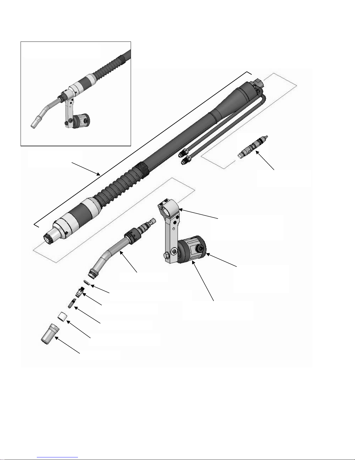
1.0 –COMPLETE ASSEMBLY OVERVIEW.............................................................................................................4
2.0 –EXPLODED VIEW AND PARTS LIST .............................................................................................................5
2.1 FRONT-END COMPONENTS ........................................................................................................................5
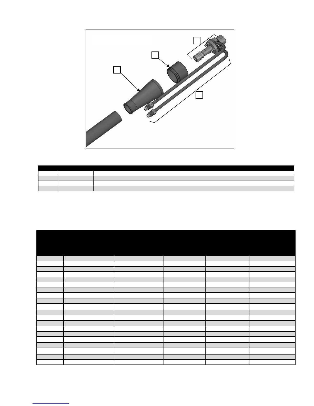
2.2 CABLE BUNDLE COMPONENTS ..................................................................................................................6
2.2.1 CABLE BUNDLE COMPONENTS –FRONT...............................................................................................6
2.2.2 CABLE BUNDLE COMPONENTS –REAR.................................................................................................7
2.2.3 CABLE BUNDLES........................................................................................................................................7
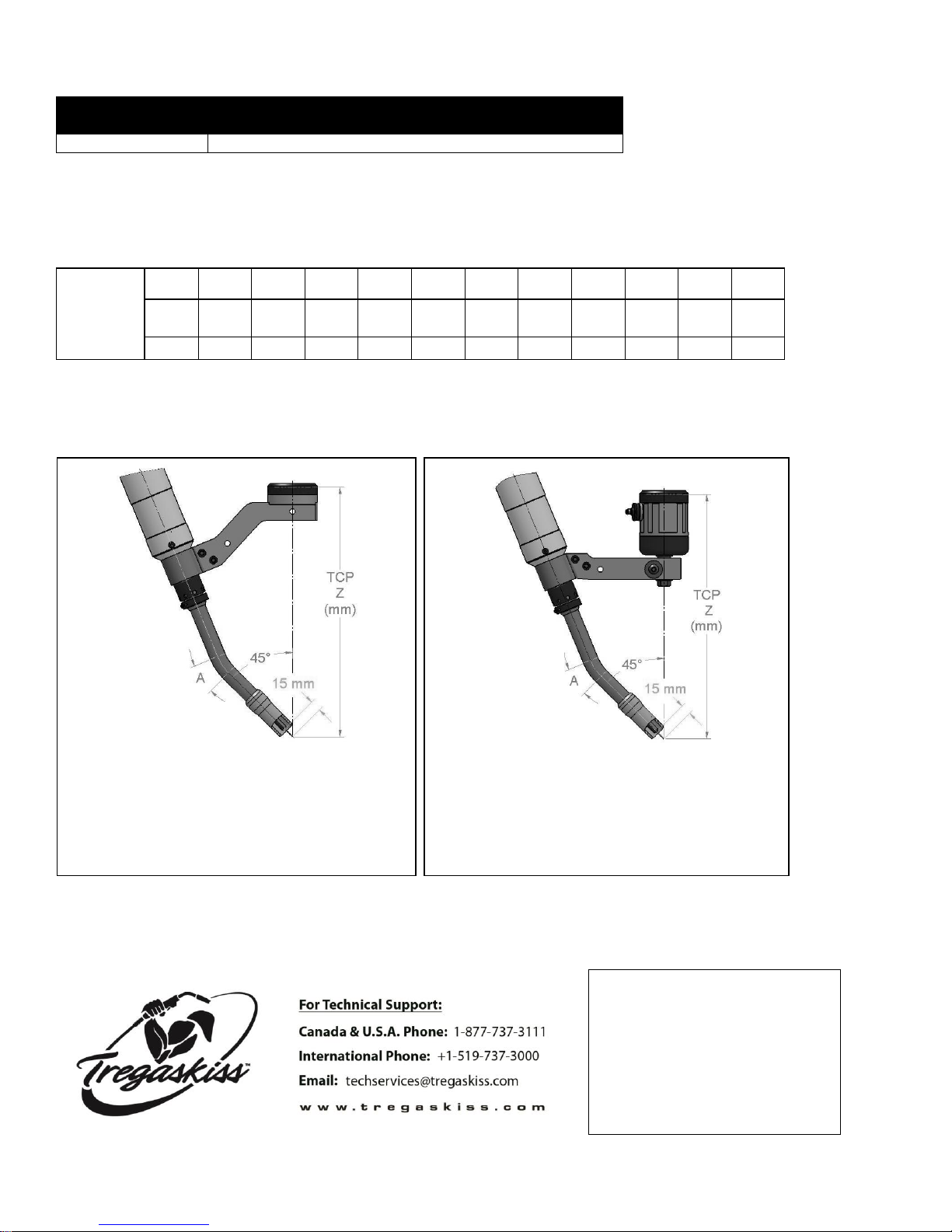
3.0 –SECURING THE NECK....................................................................................................................................8
4.0 –WIRE BRAKE OPTION ....................................................................................................................................9
4.1 WIRE BRAKE REPLACEMENT......................................................................................................................9
5.0 –AMPERAGE RATINGS ..................................................................................................................................10
6.0 –ORDERING INFORMATION ..........................................................................................................................10
THANK YOU….
…for selecting a Tregaskiss TOUGH GUN™Robotic MIG Gun. Manufacturing operations demand extremely
dependable robotic equipment. With this in mind, the TOUGH GUNMIG Gun was designed and engineered to be
a reliable tool to support high production within a robotic cell. As the name implies, the TOUGH GUN MIGGun is
made from durable materials and components engineered to perform in a rugged welding environment. Your
TOUGH GUN MIG Gun is completely assembled and ready to weld, and has undergone numerous quality checks
to ensure high performance.
The instructions and illustrations in this technical guide make it easy for you to maintain your TOUGH GUN MIG
Gun. Please read, understand, and follow all safety procedures. Keep this Technical Guide booklet as a
handy reference when ordering complete guns, parts and special options. For technical support and special
applications, call the Tregaskiss Technical Service Department at 1-855-MIGWELD (644-9353) or fax
1-877-737-2111. Our trained technicians are available Monday through Friday from 8:00 am and 5:00 pm EST
and will answer your application or repair questions.
Tregaskiss employees build TOUGH GUN MIG Guns for the world’s welding professionals. We are always
striving to improve our products and services, and would appreciate receiving your suggestions or comments.
Please contact us immediately if you experience any safety or operating problems.
WARRANTY
Product is warranted to be free from defects in material and workmanship for the period specified below after the
sale by an authorized Buyer. Should there be a defect please refer to our Return Merchandise Policy.
PRODUCT
WARRANTY PERIOD
TOUGH GUN™ Robotic MIG Guns and Components
180 days
TOUGH GUN™TT3 Reamer
1 year
TOUGH GUN™TT3 Reamer with Lubricator
3 years
TOUGH GARD™Spatter Cleaner
1 year
TOUGH GUN Robotic Peripherals (Clutch, Sprayer, Wire Cutter, Mounting Arms)
1 year
Low-Stress Robotic Unicables (LSR Unicables)
2 years
Tregaskiss reserves the right to repair, replace or refund the purchase price of non-conforming product. Product
found not defective will be returned to the Buyer after notification by Customer Service.
Tregaskiss makes no other warranty of any kind, expressed or implied, including, but not limited to the warranties
of merchantability or fitness for any purpose. Tregaskiss shall not be liable under any circumstances to Buyer, or
to any person who shall purchase from Buyer, for damages of any kind, including, but not limited to any, direct,

3
indirect incidental or consequential damages or loss of production or loss of profits resulting from any cause
whatsoever, including, but not limited to, any delay, act, error or omission of Tregaskiss.
Genuine Tregaskiss™parts must be used for safety and performance reasons or the warranty becomes invalid.
Warranty shall not apply if accident, abuse, or misuse damages a product, or if a product is modified in any way
except by authorized Tregaskiss personnel.
GENERAL SAFETY
Before installation or operation of TOUGH GUN MIG Guns, please read the safety precautions listed below.
1. Do not touch live electrical parts. The following should be checked to prevent electrical shock:
a. Faulty or damaged equipment is repaired or replaced.
b. Equipment is off when not in use.
2. Ensure that all safety devices, guards, shields or barriers are properly in place and connected correctly
before allowing operation of the equipment.
3. CSA Standard W117.2 CODE FOR SAFETY IN WELDING AND CUTTING obtainable from the Canadian
Standards Association, Standards Sales, 178 Rexdale Boulevard, Rexdale, Ontario, Canada M9W 1R3.
4. ANSI Standard Z49.1 CODE FOR SAFETY IN WELDING AND CUTTING obtainable from the American
National Standards Institute, 1430 Broadway, New York, NY 10018.
CALIFORNIA PROPOSITION 65 WARNING
This product, when used for welding or cutting, produces fumes or gases which contain chemicals known to the
State of California to cause birth defects and, in some cases, cancer.
This product contains chemicals, including lead, known to the State of California to cause cancer, and birth
defects or other reproductive harm. Wash hands after use.
(California Health & Safety Code Section 25249.5 at seq.)

4
1.0 –COMPLETE ASSEMBLY OVERVIEW
*Other mounting options are available in addition to the Clutch, including the Solid Arm Mount and TOUGH GUN G2 Style
Mounting Arm.
For a complete parts list, please proceed to Section 2.0 EXPLODED VIEW AND PARTS LIST.
ASSEMBLED SYSTEM
NOZZLE
NOZZLE INSULATOR
CONTACT TIP
GAS DIFFUSER
DIFFUSER INSULATOR
NECK
MOUNTING ARM
(Sold Separately)
CLUTCH*
(Sold Separately)
INSULATING DISC
(Sold Separately)
CABLE BUNDLE
POWER PIN

5
2.0 –EXPLODED VIEW AND PARTS LIST
2.1 FRONT-END COMPONENTS
*TOUGH GUN G2 Style Mounting Arms (AS-72-xxx-xx) require the TOUGH GUN G2 Style Insulating Disc (59Dxx).
PART #
DESCRIPTION
PART #
DESCRIPTION
1
671-6-75
Nozzle (3/4” Bore, 1/8” Recess)
N/A
415-564-10W
Conventional Liner (1/16” to 5/64”); 10’
671-8-75
Nozzle (3/4” Bore, 1/8” Stick-Out)
N/A
415-564-15W
Conventional Liner (1/16” to 5/64”); 15’
2
671-6-75-2
Nozzle Insulator
7
N/A
Neck Collar
3
403-20-xxx
TOUGH LOCK™ HD Contact Tip
8
N/A
Neck Nut
403-27-xxx
TOUGH LOCK EHD Contact Tip
9
599-3
O-Ring –Large
4
404-71
Gas Diffuser
10
ROG
O-Ring –Small
5
404-71-2
Diffuser Insulator
11
AS-71-000-22
Mounting Arm (22 Degree)
6
RW1-1000-22
Neck –22 Degree
AS-71-000-45
Mounting Arm (45 Degree)
RW1-1000-45
Neck –45 Degree
AS-72-000-22
G2 Style Mounting Arm (22 Degree)*
RW1-1000-180
Neck –180 Degree
AS-72-000-45
G2 Style Mounting Arm (45 Degree)*
N/A
415-35-6
Conventional Liner (0.035” to 0.045”); 6’
12
AS-708
Safety Clutch
N/A
415-35-10
Conventional Liner (0.035” to 0.045”); 10’
AS-730
Solid Arm Mount
N/A
415-35-15
Conventional Liner (0.035” to 0.045”); 15’
13
AS-xxx-xx
Insulating/Transition Disc (Various)
N/A
415-116-6W
Conventional Liner (0.045” to 1/16”); 6’
59Dxx
G2 Style Insulating/Transition Disc
(Various)*
N/A
415-116-10W
Conventional Liner (0.045” to 1/16”); 10’
N/A
415-116-15W
Conventional Liner (0.045” to 1/16”); 15’
N/A
415-564-6W
Conventional Liner (1/16” TO 5/64”); 6’
1
2
3
4
5
6
7
8
10
11
12
13
9

6
2.2 CABLE BUNDLE COMPONENTS
2.2.1 CABLE BUNDLE COMPONENTS –FRONT
PART #
DESCRIPTION
1
Various
Cable Bundles (See Chart Below)
2
RW1-2200
Gas / Water Line Kit –15’ Long (2 Clamps Included)
3
Various
Conduit Assembly (See Chart Below)
4
Various
Power Cable Assembly (See Chart Below)
5
Various
Cable Jacket –Leather (See Chart Below)
6
N/A
Housing Screw (3 Req.) M5X.8X6MM Low-Head SHCS
7
RW1-2140
Housing Assembly (Includes Spring)
RW1-2140-WB
Housing Assembly (Wire Brake)
8
RW1-2100-Y
Docking Body Assembly
9
214-1W
Power Pin –Miller®
214-7W
Power Pin –Lincoln®
214W
Power Pin –Tweco® #4
214-12W
Power Pin –Tweco #5
214-17W
Power Pin –Fronius®
214-30W
Power Pin –Panasonic®
214-40W
Power Pin –Lincoln (Modified)
WIRE BRAKE
450-17
Wire Brake Installation Tool
495-19-35
Wire Brake Jump Liner (0.035” to 0.045”); Water-Cooled
495-19-116
Wire Brake Jump Liner (0.045” to 1/16”); Water-Cooled
RW1-599
Wire Brake; Water-Cooled
598
Wire Brake Wire Guide (0.035” to 0.045”); Water-Cooled
598-116
Wire Brake Wire Guide (0.045” to 1/16”); Water-Cooled
499-9-15
Wire Brake Hose (15’)
ASSEMBLED
1
9
7
8
2
2
3
4
5
5
6

7
2.2.2 CABLE BUNDLE COMPONENTS –REAR
PART #
DESCRIPTION
1
RFHW600C-2
Rubber Boot
2
RFHW600C-1
Cuff
3
RW1-2700
Power Block Assembly (#30 Hoses Not Included)
4
RW1-2810-G
Water In / Out Hose Kit –6’ Long (Includes 2 Hoses, 2 Clamps, Threaded Water Fittings)
2.2.3 CABLE BUNDLES
CABLE
BUNDLE
LENGTH
CABLE BUNDLE
(POWER PIN NOT
INCLUDED)
CABLE BUNDLE FOR
WIRE BRAKE
(POWER PIN NOT
INCLUDED)
CONDUIT
ASSEMBLY
POWER CABLE
ASSEMBLY
CABLE JACKET
(LEATHER)
3.5’
RW1-2000-B
RW1-2000WB-B
RW1-2600-B
RW1-2500-B
RW1-2400-B
4.0’
RW1-2000-C
RW1-2000WB-C
RW1-2600-C
RW1-2500-C
RW1-2400-C
4.5’
RW1-2000-D
RW1-2000WB-D
RW1-2600-D
RW1-2500-D
RW1-2400-D
5.0’
RW1-2000-E
RW1-2000WB-E
RW1-2600-E
RW1-2500-E
RW1-2400-E
5.5’
RW1-2000-F
RW1-2000WB-F
RW1-2600-F
RW1-2500-F
RW1-2400-F
6.0’
RW1-2000-G
RW1-2000WB-G
RW1-2600-G
RW1-2500-G
RW1-2400-G
6.5’
RW1-2000-H
RW1-2000WB-H
RW1-2600-H
RW1-2500-H
RW1-2400-H
7.0’
RW1-2000-J
RW1-2000WB-J
RW1-2600-J
RW1-2500-J
RW1-2400-J
7.5’
RW1-2000-K
RW1-2000WB-K
RW1-2600-K
RW1-2500-K
RW1-2400-K
8.0’
RW1-2000-M
RW1-2000WB-M
RW1-2600-M
RW1-2500-M
RW1-2400-M
8.5’
RW1-2000-N
RW1-2000WB-N
RW1-2600-N
RW1-2500-N
RW1-2400-N
9.0’
RW1-2000-P
RW1-2000WB-P
RW1-2600-P
RW1-2500-P
RW1-2400-P
9.5’
RW1-2000-Q
RW1-2000WB-Q
RW1-2600-Q
RW1-2500-Q
RW1-2400-Q
10.0’
RW1-2000-R
RW1-2000WB-R
RW1-2600-R
RW1-2500-R
RW1-2400-R
10.5’
RW1-2000-S
RW1-2000WB-S
RW1-2600-S
RW1-2500-S
RW1-2400-S
11.0’
RW1-2000-T
RW1-2000WB-T
RW1-2600-T
RW1-2500-T
RW1-2400-T
12.0’
RW1-2000-U
RW1-2000WB-U
RW1-2600-U
RW1-2500-U
RW1-2400-T
13.0’
RW1-2000-V
RW1-2000WB-V
RW1-2600-V
RW1-2500-V
RW1-2400-V
14.0’
RW1-2000-W
RW1-2000WB-W
RW1-2600-W
RW1-2500-W
RW1-2400-W
15.0’
RW1-2000-Y
RW1-2000WB-Y
RW1-2600-Y
RW1-2500-Y
RW1-2400-Y
REAR COMPONENTS
3
4
2
1

8
3.0 –SECURING THE NECK
Step A:
Align dowel on neck with the hole on the docking body. Press the NECK into place. Using the spanner wrench
provided firmly tighten the “Neck Nut” onto the threaded body.
Step B:
Once neck is firmly seated in place tighten the set screw. Ensure the set screw is seated on the flat of the copper
NECK tube. [70 IN-LBS]
Tighten neck nut
with provided
spanner wrench.
Tighten the socket head set
screw onto the copper flat.

9
4.0 –WIRE BRAKE OPTION
4.1 WIRE BRAKE REPLACEMENT
Remove the neck, liner and consumables.
Inspect the jump liner for damage and replace if required.
Remove air line connected to the wire brake.
Unthread the existing wire brake from the gun housing.
Remove the wire guide and replace if necessary.
Using the 450-17 wire brake installation tool, replace the wire guide into the housing of the gun.
While holding the wire guide into position, thread the wire brake into the housing until hand-tight.
Reposition the air fitting and replace the hose.
Add the neck, jump liner and consumables to the gun housing and be sure to install to the proper torque
specifications.
450-17
Wire Brake
Installation Tool
RW1-599
Wire Brake –WC
598, or
598-116
Wire Brake Wire Guide
499-9-15
Wire Brake Hose (15’)
Gun Housing
495-19-35, or
495-19-116
Wire Brake Jump Liner
Water-Cooled NECK
Gun Housing
Water-Cooled Neck

10
5.0 –AMPERAGE RATINGS
MODEL
60% DUTY CYCLE - MIXED GASES
OR 100% DUTY CYCLE - CO2
600 amp
600 amp
NOTE: Ratings are based on tests that comply with IEC 60974-7 standards.
6.0 –ORDERING INFORMATION
STEP A: Build your custom 600 amp TOUGH GUN™Robotic Water-Cooled MIG Gun using this chart:
12345678910 11 12
Class Type Gen Amps Neck Opt 1 Opt 2
Cable
Length
Nozzle
Tip
Type
Wire
Size
Power
Pin
R W 1 6
WC Robotic
(600 amp)
Contact Tregaskiss Customer Service or visit www.tregaskiss.com/600RWC for a complete list of available options to fill in the 12
digit part number above.
STEP B: Choose Mounting System (sold separately).
STEP C: Choose Insulating Disc (sold separately).
For Steps B and C, contact Tregaskiss Customer Service or visit www.tregaskiss.com/600RWC for a complete list of available options.
Distributed by:
12/15 REV J
M081
TOUGH GUN G2 Style Solid Arm Mount System
combines the Solid Arm Mount and the Mounting
Arm into one product
Ideal for robots with collision detection software
Affixes directly to the insulating disc of the robot,
providing an increase in the work envelope of the
MIG gun
Clutch System is designed to provide maximum
protection for your robot, MIG gun and tooling
during a “crash” situation
Also available, the TOUGH GUN Solid Arm Mount
System is made from a high strength aluminum
alloy and is suitable for robots using collision
detection software
Table of contents
Other Tregaskiss Welding System manuals

Tregaskiss
Tregaskiss TOUGH GUN CA3 Series User manual

Tregaskiss
Tregaskiss TOUGH GUN TT4A User manual

Tregaskiss
Tregaskiss TOUGH GUN TT3 Reamer User manual

Tregaskiss
Tregaskiss TOUGH GUN TT REAMER Quick start guide

Tregaskiss
Tregaskiss TOUGH GUN Quick start guide

Tregaskiss
Tregaskiss TOUGH GUN CA3 Series User manual

Tregaskiss
Tregaskiss MA1 User manual
Popular Welding System manuals by other brands

HBS
HBS KAH 412 operating manual

WeldCorp
WeldCorp MIG 100 Owner's operating manual

Lincoln Electric
Lincoln Electric X-TRACTOR 1G IM281-B Operator's manual

Sweiss
Sweiss PURE WELDING SKYWORKS 3550 user manual

Lincoln Electric
Lincoln Electric Power Wave S500 K2904-1 Operator's manual

ESAB
ESAB Aristo Mig U4000iw instruction manual