Trek II SSP-1C User manual

The Trek II®SSP-1C is designed to replace the AO-15331 two tube (#56-#57) pre-amp used in Hammond®A, AB, B, BC,
C, D and G consoles. The unit features a built in power supply and tremolo control circuitry for Leslie®speakers in the 122
family (models 21H, 22H, 22R, 31H above serial #5200, 122, 122A, 122RV, 122V, 142, 222, 222RV, and 242).
NOTE: The SSP-1C does NOT replace the AO-16875 five tube pre-amp which was used in BV, CV, and RT consoles as
well as in earlier organs which had vibrato kits installed.
1. Remove all wires from the left hand AC terminal of the old pre-amp. Remove all lugs and strip 3/8" insulation from
each wire. Temporarily group the wires together with a twist tie.
2. Remove all wires from the right hand AC terminal. Remove all lugs and strip 3/8" insulation from each wire.
Temporarily group the wires together with a twist tie.
3. Remove the wire going to the B+ lug. This wire brings high B+ voltage back from the tone cabinet and is no longer
used. Insulate this wire with tape or heatshrink.
4. Remove the remaining ground and GG leads from the pre-amp. Remove all lugs.
5. Remove cover from rheostat box and note the location of the black and red wires of the pre-amp signal cable. Unsolder
these wires.
6. Remove old pre-amp and mounting pan (model A only) from console.
NOTE: Because of their narrow case, model A consoles used a different pre-amp mounting method than other consoles.
Therefore SSP-1C mounting will be slightly different in those organs. Separate instructions are given where necessary.
SSP-1C SOLID STATE PRE-AMP
GENERAL INFORMATION
WARNING! INSTALLATION OF THIS UNIT REQUIRES DIRECT CONNECTION TO THE AC POWER WIRING AND MUST
BE PERFORMED BY QUALIFIED PERSONNEL ONLY.
NOTE: PLEASE LEAVE THIS INSTRUCTION / SCHEMATIC SET IN ORGAN
INSTALLATION
WARNING! BEFORE PROCEEDING WITH INSTALLATION, DISCONNECT AC POWER FROM THE ORGAN AND
INSPECT THE CONSOLE POWER WIRING FOR BRITTLE OR ROTTING INSULATION.
TREK II PRODUCTS 570 JERSEY AVENUE NEW BRUNSWICK, NJ 08901 USA
TEL: 732-214-9200 FAX: 732-214-9257 www.TrekII.com
Rev. 11/14/05 © 2005 Trek II Products

MODEL A ORGANS
7. Temporarily position the SSP-1C chassis on the
mounting pan. The shielded wire should be facing the
right and the edge of the right mounting flange should
be about 1-1/2" in from the end of the pan. Mark the
pan with the location of the 2 small mounting holes on
each mounting flange. Drill a 7/64" hole at each mark.
8. Secure the SSP-1C to the mounting pan with 4) #6 x
1/4" sheet metal screws.
9. Reinstall the mounting pan on the two support brackets
using 2) #8-32 x 3/8" screws, along with original
lockwashers and nuts at each end.
10. Route the SSP-1C shielded cable into the rheostat box. Solder the inner conductor to the lug where the original red wire
was soldered. Solder the shield to the ground lug where the original black wire was soldered. Replace rheostat box
cover.
11. Mate one wire of the SSP-1C zip cord with the AC wires grouped in step 1 using a yellow wire nut. Mate the remaining
wire of the zip cord with the AC wires grouped in step 2 using a yellow wire nut.
NOTE: The terminal strip on the SSP-1C allows easy connection of the output and tremolo control wires. Each wire should
have approximately 5/16" of insulation removed. Wires are attached by loosening (but not removing) the terminal screw,
placing the wire under the clamping bar, and re-tightening the screw.
NOTE: This pre-amp contains all necessary switching circuitry for 122 and similar type Leslie tone cabinets.
12. If a 122 type Leslie is being used, remove the Leslie 8,000 kit from organ (if present). Attach one of the tremolo switch
wires to the LC terminal. Attach the second tremolo switch wire to the end GND terminal.
13. If a 122 type Leslie is being used, connect its red and black signal wires to the G1 and G2 terminals. Connect its ground
wire to the GND terminal.
14. If a Hammond tone cabinet is being used, connect its red and black signal wires to the G3 and G4 terminals. Connect its
ground wire to the GND terminal.
15. Dress all leads and secure where necessary with supplied twist ties. Re-connect AC power to organ.
16. Adjust tone control to customer preference.
This completes normal installation.
ALL OTHER MODELS
Install a plastic spacer in each of the 2 large holes in the
right SSP-1C mounting flange. Position the SSP-1C
chassis on the channel so that the left mounting flange is
over the left two threaded mounting posts. Secure using
2) #8-32 x 3/8" screws. On organs with a chorus
generator, it may be necessary to move the oil tube
slightly for clearance.
Place a sheet of paper under the channel to catch any
metal chips. Through each of the plastic spacers,
carefully drill a 7/64" hole through the channel.
Secure the right end of the SSP-1C with 2) #6 x 3/4"
sheet metal screws.
-2-

Although standard Hammond tone cabinets or Leslie model 122s are recommended, many other successful output
configurations are possible. When using one of the Leslies listed below, mount the appropriate receptacle in the organ outlet
box and wire as shown.
____________________________________________________________________________________________________
OUTLET WIRING FOR LESLIE MODELS:
122XB, 315, 330, 415, 422, 615, 715, 716, 722, 723, 740, 750, 771, 815, 820, 822, 840, 860, 912, 914
____________________________________________________________________________________________________
OUTLET WIRING FOR LESLIE MODELS:
760, 770, 900, 910, 925
____________________________________________________________________________________________________
ADDITIONAL OUTPUT CONFIGURATIONS
-3-
TREMOLO
TS-2 (OR OTHER) TREMOLO SWITCH
CHORALE
78S9 SOCKET
(REAR VIEW)
78S11 SOCKET
(REAR VIEW)
12
3
4
5
6
7
89
VIOLET
WHITE
BLACK
INSULATE WITH HEAT SHRINK TUBING
RED
BROWN GROUND
G4 (SIGNAL)
PRE-AMP
TERMINALS
GREY BLUE
SWITCHED
AC LINE
123
4
5
6
7
8
91011
TREMOLO
TS-2 (OR OTHER) TREMOLO SWITCH
CHORALE
GROUND
G4 (SIGNAL)
PRE-AMP
TERMINALS
RED
BROWN
VIOLET
WHITE
BLACK
SWITCHED AC LINE
GY/BLACK
GY/WHITE
TREK II POR-11
OR OTHER
120V AC RELAY

____________________________________________________________________________________________________
OUTLET WIRING FOR LESLIE MODELS:
44W, 45, 46W, 47, 145, 147, 147A, 147RV, 245, 247, 247RV
NOTE: LESLIES IN THIS GROUP MUST HAVE THEIR CONSOLE LOAD SELECTOR SET TO OPEN
____________________________________________________________________________________________________
OUTLET WIRING FOR LESLIE MODELS:
51, 251, 351
____________________________________________________________________________________________________
WIRING FOR LINE OUTPUT
-4-
WARNING! ALL RECEPTACLES
WITH THIS WIRING MUST BE
CLEARLY MARKED "WIRED
FOR 147 TYPE ONLY !"
WARNING! ALL RECEPTACLES
WITH THIS WIRING MUST BE
CLEARLY MARKED "WIRED
FOR 251 TYPE ONLY !"
G4 (SIGNAL)
GROUND
PRE-AMP
TERMINALS
RED
BROWN
5K
OUTPUT LEVEL
1/4" PHONE JACK
OR PREFERRED CONNECTOR
1K
2
3
4
516
TREMOLO
TS-2 (OR OTHER)
TREMOLO SWITCH
RED G4 (SIGNAL)
GROUND
BROWN
PRE-AMP
TERMINALS
BLUE
GREY
SWITCHED
78S6 SOCKET
(REAR VIEW)
AC LINE
CHORALE
2
3
4
516
TREMOLO
TS-2 (OR OTHER)
TREMOLO SWITCH
RED G4 (SIGNAL)
GROUND
BROWN
PRE-AMP
TERMINALS
BLUE
GREY
SWITCHED
78S6 SOCKET
(REAR VIEW)
AC LINE
CHORALE
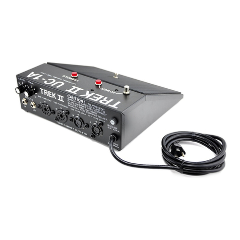
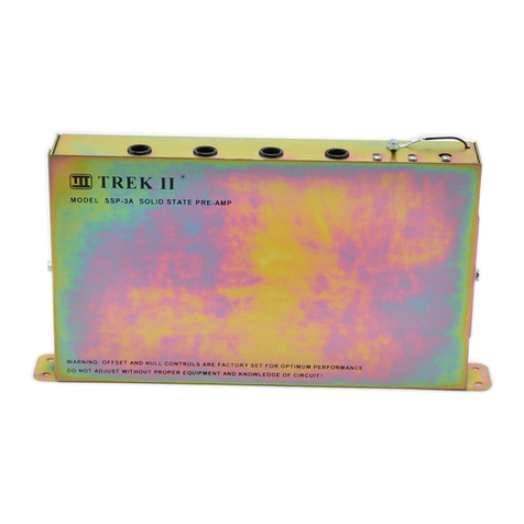
Other Trek II Amplifier manuals
Popular Amplifier manuals by other brands
Audiodesign
Audiodesign HXP4 installation guide
digital world
digital world ARC-016B user manual
Contro l4
Contro l4 C4-AMP104 Installation and setup guide
Audio Control
Audio Control Maestro M8 User experience manual
Aetechron
Aetechron 7548 Operator's manual

IMG STAGE LINE
IMG STAGE LINE STA-1000D instruction manual
