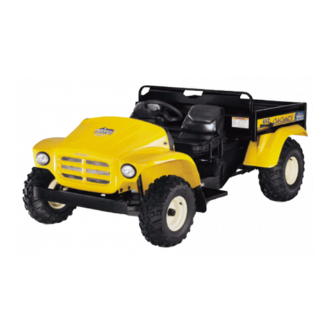
Treker 4220ST User manual

Cover photo may show optional equipment not supplied
with standard unit.
© Copyright 2007 Printed
Read the Operator’s manual entirely. When
you see this symbol, the subsequent
instructions and warnings are serious - follow
without exception. Your life and the lives of
others depend on it!
!
Table of Contents
700-504M
8/05/08
4220ST & 4420ST Light Utility Vehicles
Operator’s Manual
24700
Treker

8/05/08
4220ST & 4420ST Light Utility Vehicles 700-504M
©Copyright 2007 All rights Reserved
LandPride providesthispublication“asis”withoutwarrantyofanykind,eitherexpressedorimplied.Whileeveryprecautionhasbeentakeninthepreparationofthismanual,
Land Pride assumes no responsibility for errors or omissions. Neither is any liability assumed for damages resulting from the use of the information contained herein. Land
Pride reserves the right to revise and improve its products as it sees fit. This publication describes the state of this product at the time of its publication, and may not reflect
the product in the future. The illustrations in this manual are not intended for safe and proper assembly or disassembly of equipment. The illustrations are intended for
ordering parts only. Land Pride is a registered trademark.
Weather Pro G is a registered trademark of Spartech Plastic
All other brands and product names are trademarks or registered trademarks of their respective holders.
Printed in the United States of America.
Section 1: Introduction . . . . . . . . . . . . . . . . . . 1
Safety First . . . . . . . . . . . . . . . . . . . . . . . . . . . . . . 1
Using This Manual . . . . . . . . . . . . . . . . . . . . . . . . .1
Terminology . . . . . . . . . . . . . . . . . . . . . . . . . . . . 1
Definitions . . . . . . . . . . . . . . . . . . . . . . . . . . . . . 1
Application . . . . . . . . . . . . . . . . . . . . . . . . . . . . . . . 1
Models Covered . . . . . . . . . . . . . . . . . . . . . . . .1
Getting Acquainted with your Treker . . . . . . . . .1
Owner Assistance . . . . . . . . . . . . . . . . . . . . . . . . . 2
Serial Number Plate . . . . . . . . . . . . . . . . . . . . . . . .2
Section 2: Important Safety Information . . . . 3
Look For The Safety Alert Symbol . . . . . . . . . . . . .3
Be Aware of Signal Words . . . . . . . . . . . . . . . . . . . 3
Safe Operating Procedures . . . . . . . . . . . . . . . . . .5
Personal Safety . . . . . . . . . . . . . . . . . . . . . . . . . 5
Mechanical Safety . . . . . . . . . . . . . . . . . . . . . . .5
Transporting Safety . . . . . . . . . . . . . . . . . . . . . . 6
Towing Safety . . . . . . . . . . . . . . . . . . . . . . . . . .7
Safe Load Capacities . . . . . . . . . . . . . . . . . . . . 7
Safety Decals . . . . . . . . . . . . . . . . . . . . . . . . . . . . 8
Section 3: Pre-Delivery and Check List . . . . 13
Pre-Delivery Certificate . . . . . . . . . . . . . . . . . . . .13
Vehicle Information . . . . . . . . . . . . . . . . . . . . . 13
Dealer Service and Inspection List . . . . . . . . . 13
Dealer Test Ride List . . . . . . . . . . . . . . . . . . . . 14
Dealer Delivery To Customer List . . . . . . . . . . 14
Customer Acceptance List . . . . . . . . . . . . . . . 14
Section 4: Operating Instructions . . . . . . . . 15
Operator Responsibilities . . . . . . . . . . . . . . . . . . . 15
Pre-Start Check List . . . . . . . . . . . . . . . . . . . . 15
General Operation . . . . . . . . . . . . . . . . . . . . . . . . 15
Indicating Lights and Gauges . . . . . . . . . . . . . . .16
Switches . . . . . . . . . . . . . . . . . . . . . . . . . . . . . . . 16
Choke . . . . . . . . . . . . . . . . . . . . . . . . . . . . . . . . . 17
Floor Pedals . . . . . . . . . . . . . . . . . . . . . . . . . . . . . 17
Shift Selector and Park Brake . . . . . . . . . . . . . . . 17
Fuel Gauge . . . . . . . . . . . . . . . . . . . . . . . . . . . . . 18
Seat Belts . . . . . . . . . . . . . . . . . . . . . . . . . . . . . . 18
Cup Holders . . . . . . . . . . . . . . . . . . . . . . . . . . . . . 18
Glove Box Enclosure . . . . . . . . . . . . . . . . . . . . . . 19
Cargo Box / Flat Bed Set-Up . . . . . . . . . . . . . . . .19
Towing . . . . . . . . . . . . . . . . . . . . . . . . . . . . . . . . . 20
Engine Performance . . . . . . . . . . . . . . . . . . . . . . 20
Fuel Quality . . . . . . . . . . . . . . . . . . . . . . . . . . . 20
Incomplete Combustion . . . . . . . . . . . . . . . . . . 20
Cold Weather Operation . . . . . . . . . . . . . . . . . 20
Traveling Tips From the Trail Masters . . . . . . . . . . 21
Table of Contents
Section 5: Options and Accessories . . . . . . . 23
Treker Options . . . . . . . . . . . . . . . . . . . . . . . . . . .23
Front Bumper . . . . . . . . . . . . . . . . . . . . . . . . . .23
Heavy Duty Brush Guard . . . . . . . . . . . . . . . . .23
Tires . . . . . . . . . . . . . . . . . . . . . . . . . . . . . . . .23
Treker Accessories . . . . . . . . . . . . . . . . . . . . . . . .24
Section 6: Maintenance . . . . . . . . . . . . . . . . . 25
General Maintenance . . . . . . . . . . . . . . . . . . . . . .25
Securing Vehicle for Maintenance . . . . . . . . . . . .25
Torque Values . . . . . . . . . . . . . . . . . . . . . . . . . . .25
Tire Maintenance . . . . . . . . . . . . . . . . . . . . . . . . .25
Jacking the Vehicle . . . . . . . . . . . . . . . . . . . . . . . .26
Shock Absorber Adjustment . . . . . . . . . . . . . . . . .26
Electrical System . . . . . . . . . . . . . . . . . . . . . . . . .27
Battery . . . . . . . . . . . . . . . . . . . . . . . . . . . . . . . . .27
Adding Water to the Battery . . . . . . . . . . . . . . . . .28
Charging the Battery . . . . . . . . . . . . . . . . . . . . . .28
Jump Starting the Battery . . . . . . . . . . . . . . . . . .28
Fuel System . . . . . . . . . . . . . . . . . . . . . . . . . . . . .29
Engine Maintenance . . . . . . . . . . . . . . . . . . . . . .30
General Information . . . . . . . . . . . . . . . . . . . . .30
High Altitude Carburetor Kit . . . . . . . . . . . . . . .30
Drive Belt Replacement . . . . . . . . . . . . . . . . . . . .31
Driven Pulley Maintenance . . . . . . . . . . . . . . . . . .31
Engine Air Filter Maintenance . . . . . . . . . . . . . . .32
Engine Air Filter Handling . . . . . . . . . . . . . . . . . .32
CVT Snorkel Filter Maintenance . . . . . . . . . . . . .33
Exhaust System . . . . . . . . . . . . . . . . . . . . . . . . . .34
Spark Arrester . . . . . . . . . . . . . . . . . . . . . . . . .34
Park Brake Adjustment . . . . . . . . . . . . . . . . . . . . .35
Maintenance Schedule . . . . . . . . . . . . . . . . . . . . .36
Section 7: Lubrication . . . . . . . . . . . . . . . . . . 37
Engine Oil . . . . . . . . . . . . . . . . . . . . . . . . . . . . . .37
Case Oil . . . . . . . . . . . . . . . . . . . . . . . . . . . . . . . .39
Rear Trans-axle Case . . . . . . . . . . . . . . . . . . .39
Center Transfer Case . . . . . . . . . . . . . . . . . . .40
Front Differential Case . . . . . . . . . . . . . . . . . . .40
Brake Fluid . . . . . . . . . . . . . . . . . . . . . . . . . . . . . .41
Section 8: Seasonal Storage . . . . . . . . . . . . . 42
Section 9: Body Repair . . . . . . . . . . . . . . . . . 43
Section 10: Specifications and Capacities . . 45
Section 11: Features and Benefits . . . . . . . . 46
Section 12: Troubleshooting . . . . . . . . . . . . . 47
Section 13: Appendix . . . . . . . . . . . . . . . . . . . 51
Torque Values Chart . . . . . . . . . . . . . . . . . . . . . .51
Tire Inflation Chart . . . . . . . . . . . . . . . . . . . . . . . .51
Notes . . . . . . . . . . . . . . . . . . . . . . . . . . . . . . . . . .52
Land Pride Limited Warranty . . . . . . . . . . . . . . . .53

8/05/08 1
Section 1: Introduction
4220ST & 4420ST Light Utility Vehicles 700-504M
Table of Contents
Land Pride welcomes you to its growing family of new
product owners. Treker series trucks are light utility
vehicles that have been designed with care and built by
skilled workers using quality materials. Proper set-up,
maintenance and safe operating practices will help you
get years of satisfactory use from this vehicle.
Safety First
Land Pride is fully aware of the need for safe operating
procedures around all of our equipment. We hope you
will make a sincere effort to put safety above all other
priorities. The Trekers are designed and built for work,
recreation and enjoyment; however, improper and
irresponsible operation could result in serious injury or
death. Since this is an off-road vehicle, operators will
seldom see road safety and warning signs they are
accustomed to seeing on highways and public streets.
This places additional responsibility on the driver to
operatethisvehiclewellwithinsafeoperationallimitsand
capabilities of the unit.
Thismanualhasbeenpreparedtoinstructyouinthesafe
and responsible operation of your Treker. Please read
and abide by all safety alert information about this
vehicle. If you do not understand any part of this manual,
contact your local dealer for additional information and
clarification. As the operator of this piece of equipment,
you are in complete control. Only you can prevent an
accident from happening!
Using This Manual
•Prior to any vehicle operation it is absolutely essential
that you read and comprehend each section in this
manualtodevelopanunderstandingofyourvehicle and
safetypractices.Afterreviewingthismanual,storeitina
dry and easily accessible place for future reference.
•The Operator’s Section is designed to help familiarize
you with safety, assembly, operation, adjustments,
troubleshooting and maintenance. Read this manual
and follow recommendations to help ensure safe and
efficient operation.
•The information contained within this manual was
current at the time of printing. Some parts may change
slightly to assure you of the best performance.
•Toorder a new Operator’s or Parts Manual contact your
authorized dealer. Manuals can also be downloaded,
free-of-charge from our website at www.landpride.com
orprintedfromtheLandPrideService&SupportCenter
by your dealer.
Terminology
Right-hand and left-hand as used in this manual are
determined by facing the direction the vehicle will travel
while in use unless otherwise stated.
Definitions
The following terms are used throughout this manual.
Application
Models Covered
4220ST 4x2 and 4420ST 4x4
Getting Acquainted with your Treker
TheTrekerlineoflightutilityvehiclesisdesignedbyLand
Pride exclusively for off-road use. They are not designed
for, nor are they properly equipped to be safely operated
orlicensedforuseonpublicstreetsandhighways.These
vehicles are designed to carry two to three people and a
limited amount of gear or cargo comfortably and safely
over rough or difficult off road terrain.
The wide stance ST series is designed to carry three
passengerson thebench seat and900 lbs.ofcargo in its
15.9cu-ft.capacitydumpingcargoboxforatotalpayload
capacity of 1,300 lbs. The wide stance, long wheelbase,
and high payload make the ST series Trekers a strong
and stable workhorse for ranches, farms, and
construction sites.
The 4220ST series (4x2) is equipped with two wheel
traction drive and the 4420ST series (4x4) is equipped
with four wheel traction drive. Both series have an
automotive steering wheel with easy handling rack-and-
pinion steering, four wheeled independent suspension,
McPherson Struts, large diameter hi-flotation tires, and
high center-frame ground clearances that add up to
excellent stability and smooth ride over tough terrain.
The 4420ST series feature our Command Track four
wheel drive system with over-running clutches on the
front differential for unexcelled traction, easy handling
and minimal disturbance to the turf. These models also
feature Auto-Lock rear differentials with over-running
clutches and sealed torque converters for absolute
maximumtractioncapabilityinwetorslipperyconditions.
Seat belts for two passengers are standard. An
additional seat belt may be added for the center third
person.
IMPORTANT: A special point of information related to
its preceding topic. Land Pride’s intention is that this
information should be read and noted before
continuing.
NOTE: Aspecialpoint ofinformation that the operator
must be aware of before continuing.
Section 1: Introduction

Section 1: Introduction
4220ST & 4420ST Light Utility Vehicles 700-504M 8/05/08
2
Table of Contents
Driving a Treker is as easy as driving a pickup with an
automatic transmission. A simple forward and reverse
shifter provides direction control. A neutral start feature
and keyed 12-volt electronic ignition make for safe and
easy starting. We have even provided a manual choke
controlwithspring-loadedreturnforquickercoldweather
starting. The infinitely variable torque converter drive
system means there is no clutching; you just shift into
either forward or reverse and step on the throttle pedal to
go at speeds up to 25 mph. All Trekers are powered by
highly reliable and proven 20 hp. Honda engines that are
EPA certified and meet California Air Resources Board
(CARB) certification standards.
Braking is accomplished by simply depressing the brake
pedal located on the floorboard. This activates the rear
hydraulic drum brakes and front mounted disc brakes.
The park brake is incorporated into the dash-mounted
shifter so when you put the vehicle in park you
simultaneously set the park brake. All models come with
a very strong 4-post accessory bar that provides extra
protection against low hanging limbs and brush as well
as providing a mounting system for accessories such as
windshields, canopy tops, and weather enclosures. The
4-post accessory bar also provides a mounting base for
accessories such as cargo racks, gun and bow racks,
back screens, tree stands, and camping or fishing gear
and tool holders. A standard rear receiver enables quick
installation of a hitch to pull small trailers full of supplies,
tools, gear, or game.
Owner Assistance
The safety video should be viewed by the owner and the
Warranty Registration card should be filled out by the
dealer at the time of purchase. The owner should also
receive a copy of the safety video upon purchasing the
vehicle as well as have participated in a short drivers
training course with the dealer. This information is
necessary to provide you with quality customer service.
The parts on your Treker Light Utility Vehicle have been
specially designed and should only be replaced with
genuine Land Pride parts.
If customer service or repair parts are required contact a
Land Pride vehicle dealer. They have trained personnel,
genuine repair parts and equipment specially designed
to repair Land Pride products.
Serial Number Plate
Refer to Figure 1:
Always use serial and model number when ordering
parts from your Land Pride dealer. The serial-number
plate is located on the driver’s side just left of the rear tail
light as shown in figure 1 below.
Serial Number Plate
Figure 1
Record your vehicle model number (4220ST or 4420ST)
and serial number here for quick reference:
Model Number:__________________________
Serial Number: ___________________________
YourLandPridedealerwantsyoutobe satisfied withyour
new vehicle. If you do not understand any part of this
manual or are not satisfied with the service received,
please take the following actions.
1. Discuss the matter with your dealership service
manager. Make sure they are aware of any problems
so they can assist you.
2. If you are still unsatisfied, seek out the owner or
general manager of the dealership.
3. For further assistance write to:
Product Support
Land Pride Service Department
1525 East North Street
P.O. Box 5060
Salina, Ks. 67402-5060
E-mail address
lpser[email protected]
21121

8/05/08 3
Section 2: Important Safety Information
4220ST & 4420ST Light Utility Vehicles 700-504M
Table of Contents
!
Look For The Safety Alert
Symbol
TheSAFETY ALERTSYMBOL indicates there is
a potential hazard to personal safety involved
andextrasafetyprecaution mustbetaken.When
you see this symbol, be alert and carefully read
the message that follows it. In addition to design
and configuration of equipment, hazard control
and accident prevention are dependent upon the
awareness, concern, prudence and proper
training of personnel involved in the operation,
transport, maintenance and storage of
equipment.
Be Aware of Signal Words
A signal words designate a degree or level of
hazard seriousness. The signal words are:
!DANGER
DANGERindicatesanimminentlyhazardoussituation
which, if not avoided, will result in serious or death
injury. This signal word is limited to the most extreme
situations, typically for vehicle components that, for
functional purposes, cannot be guarded.
!WARNING
WARNING indicates a potentially hazardous situation
which, if not avoided, could result in death or serious
injury, and includes hazards that are exposed when
guards are removed. It may also be used to alert
against unsafe practices.
!CAUTION
CAUTION indicates a potentially hazardous situation
which, if not avoided, may result in minor or moderate
injury. It may also be used to alert against unsafe
practices.
For Your Protection
▲Thoroughly read and understand
the instructions given in this
manual before operation. Refer to
the “Safety Label” section, read all
instructions noted on the decals.
▲Do not allow anyone to operate
this equipment who has not fully
read and comprehended this
manual and who has not been
properly trained in the safe
operation of the equipment. OFF
Before Operating
▲This Treker Light Utility Vehicle is
not to be driven on public roads.
▲Do not operate this vehicle under
the influence of alcohol or drugs.
▲Always inspect the vehicle before
operating it. See "Pre-Start Check
List" on page 15.
▲Do not operate this machine
unless all safety shields are in
place and all badly worn, broken or
missing parts have been properly
replaced.
▲Wear appropriate protective gear
and clothing such as safety
helmet, goggles, gloves, coveralls,
etc., when conditions warrant.
▲No driver under age of 16.
Section 2: Important Safety Information
These are common practices that may or may not be applicable to the products described in
this manual.
IMPORTANT: Read and understand all pages in this manual thoroughly before operating your vehicle.

Section 2: Important Safety Information
4220ST & 4420ST Light Utility Vehicles 700-504M 8/05/08
4
Table of Contents
Practice Safe
Maintenance
▲Understand procedure before
doing work. Use proper tools and
equipment.Referto this manualfor
additional information.
▲Work in a clean, dry area.
▲Place the vehicle in neutral, set
parking brake, turn off engine and
remove key before performing
maintenance. Chock wheels if you
must perform maintenance on a
slope.
911
OFF
▲Make sure all moving parts have
stopped and all system pressure is
relieved.
▲Allow the engine to cool completely.
▲Disconnect battery ground cable (-)
before servicing or adjusting
electrical systems or before
welding.
Prepare for
Emergencies
▲Be prepared if a fire starts.
▲Keep a first aid kit and fire
extinguisher handy.
▲Keep emergency numbers for
doctor, ambulance, hospital and
fire department near phone.
▲Inspect all parts. Make sure parts
are in good condition and installed
properly.
▲Remove build-up of grease, oil or
debris.
▲Remove all tools and unused parts
from the Treker before operation.
Wear Protective
Equipment
▲Wear protective clothing and
equipment.
▲Wear clothing and equipment
appropriate for the job. Avoid
loose-fitting clothing.
▲Because prolonged exposure to
loud noise can cause hearing
impairment or hearing loss, it is
best to wear suitable hearing
protection such as earmuffs or
earplugs.
▲Because operating equipment
safely requires your full attention,
avoid wearing radio headphones
while operating machinery.
▲It is the discretion of the operator
and passenger to wear Seat Belts
when available.
Tire Safety
Tire changing can be dangerous
andshouldbeperformedbytrained
personnel using correct tools and
equipment.
▲When inflating tires, use a clip-on
chuck and extension hose long
enough for you to stand to one
side–not in front of or over tire
assembly. Use a safety cage if
available.
▲When removing and installing
wheels, use wheel-handling
equipment adequate for weight
involved.
These are common practices that may or may not be applicable to the products described in
this manual.

8/05/08 5
Section 2: Important Safety Information
4220ST & 4420ST Light Utility Vehicles 700-504M
Table of Contents
Safe Operating Procedures
The safe operation of any machinery is a big concern to
allconsumers.YourTrekerhasbeen designed withmany
built-in safety features. However, no one should operate
this vehicle before carefully reading this Operator’s
Manual. Also read all instructions noted on the safety
decals.
Personal Safety
▲Be familiar with all functions of this vehicle.
▲Do not allow anyone to operate this vehicle who has not
fully read and comprehended this manual and who has
not been properly trained in the safe operation of this
vehicle.
▲Do not operate vehicle while drinking or under the
influence of alcohol or drugs.
▲Do not allow anyone under 16 years of age to operate
this vehicle even under adult supervision.
▲Do not run engine indoors except when starting engine
and transporting attachment in or out of a building.
Carbon monoxide gas is colorless, odorless and deadly.
▲Operator must always use both hands on the steering
wheel.
▲Keep all bystanders away from this vehicle during
operation. Keep children out of the operating area and
under the watchful eye of another responsible adult.
▲Riders may, without knowing it, place their foot on the
accelerator pedal while bracing themselves against a
rough ride. This makes it impossible to slow down the
vehicle until the passenger removes his foot from the
pedal. Inform passenger to keep his foot off the
accelerator and always slow down before the ride gets
rough.
▲Operator and passenger are responsible for deciding if
their situation warrants using seat belts if so equipped.
▲No riders are allowed except in factory designed and
supplied seating and no more than one person in a
bucket seat and three people in a bench seat. Do not use
cargo bed for carrying people. Maximum vehicle
occupancy including driver is one person per seat
position.
▲Operate vehicle from driver’s seat only.
▲Do not leave vehicle unattended with engine running.
▲Do not dismount a moving vehicle as serious injury or
death could occur.
▲Wear snug-fitting clothing to avoid entanglement with
moving parts.
▲Keep hands, feet, long hair, clothing and jewelry away
from moving parts and obvious pinch points to avoid
getting caught.
▲Keep hands, arms, feet and all bodily appendages safely
inside the confines of the vehicle. Always be aware of and
avoid tree limbs and brush that have a potential of hitting
and/or poking individuals riding the vehicle. Serious body
harm could result.
▲Some conditions may warrant extra safety gear to be
worn such as safety helmets and/or goggles.
▲Do not touch engine, engine exhaust pipe and/or muffler
while they are hot.
▲Avoid pinch point hazards. Cargo bed and seat platform
hinge creating pinch points.
▲Battery fumes are explosive. A spark will ignite battery
fumes. Wear a face shield when charging or jumping a
battery. Follow all battery safety rules outlined in this
manual.
▲Avoid battery acid spills. Do not get battery acid on eyes,
face, or other body parts. Flush eyes and other body
parts immediately with water for at least 15 minutes if
battery acid has gotten on them.
▲When refueling use a UL approved nonmetallic container
that has no screen or filter. Set container on the ground
before fueling to eliminate static discharge and do not use
Methanol fuel.
▲Do not smoke or use electrical devices including cell
phones while refueling.
▲Support this vehicle securely before working beneath.
Chock wheels to prevent vehicle from rolling.
Mechanical Safety
▲Do not operate a vehicle with damaged or worn parts.
Repair all damages and worn parts before putting vehicle
back in to service.
▲Never attempt to make any adjustments while engine is
running or hot. Keep clear of all rotating parts.
▲Make sure engine surface, cooling fins and fan screen
are clean of all debris including dirt, trash and oil.
▲Always operate vehicle with drive belt enclosure installed.
Do not leave pulleys and belts exposed.
▲Never modify any parts on the vehicle without
authorization. Unauthorized modifications will void
warranty to all parts directly and indirectly affected by the
modification.
▲Do not use cargo tail gate as a seat.
▲Do not use cargo bed as a working platform.
▲The power lift is designed to dump cargo only. Do not use
it to lift other objects.
▲Never attempt “wheelies”, jumps, or other stunts. Never
drive recklessly. Always operate your vehicle at a safe
speed that will allow you to maintain control.
▲Do not use vehicle as an anchor device.

Section 2: Important Safety Information
4220ST & 4420ST Light Utility Vehicles 700-504M 8/05/08
6
Table of Contents
▲Do not mount a receiver hitch type carrier platform to the
vehicle.
▲Front bumper, brush guards and cargo box are not
designed as pusher bars. Do not attempt to push other
vehicles or implements or damage may result.
▲Always maintain proper tire inflation. See "Tire
Maintenance" on page 25.
▲Always disconnect negative battery terminal before
making adjustments to vehicle electrical system or
welding on this vehicle.
▲Always check wheel lug nut torque values two hours after
initial operation and two hours after each tire repair or
replacement. Routinely check lug nut torque every 100
hours of operation. See "Wheel Lug Nuts" on page 25.
▲Do not shift trans-axle unless this vehicle is fully stopped
and engine is at idle or damage may occur.
▲Keep safety decals clean of dirt and grime.
▲Replace all missing, illegible, or damaged safety decals.
See list of safety decals in this manual.
Transporting Safety
!WARNING
Most accidents with off road vehicles occur when traveling up,
down, or across the face of a slope. Refer to operation
instructions and safety video for proper operation procedures.
▲Use extreme caution when driving through dry grass,
brush and other fire hazard materials. Never stop or park
over combustible materials. Keep grass and brush from
collecting on and around engine and muffler parts.
▲Be aware of cargo shifting when stopping or moving.
Make sure all cargo is properly secured and tied down.
Injury could result from loose cargo.
▲Avoid sudden stops, starts and turns.
▲Always make sure vehicle pathway is clear of all objects
when backing up. Know location of persons around
vehicle and especially location of small children. Take
extra precautions when rear view is hindered by cargo.
▲Do not attach an implement, trailer or other device to the
hitch that will produce negative tongue weight.
▲Reduce speed and payload on hilly, rough, wet, slick or
unstable ground.
▲Reduce speed when loaded with cargo. Heavy cargo load
takes longer to stop.
▲Always make turns at a speed that will maintain control of
vehicle. Never make turns at full speed. Reduce speed
when turning empty and reduce speed even more when
turning loaded. The heavier the cargo load, the slower the
turn should be.
▲The 4-post accessory bar is not a certified ROPS (Roll
Over Protection System). Always avoid roll-overs.
▲Do not load 4-post accessory bar with heavy equipment.
Rollover could result from such loading.
▲Always park on level ground, stop engine, set park brake
(see "Shift Selector and Park Brake" on page 17) and
remove ignition key before leaving vehicle. Chock tires if
condition warrants.
▲Use extreme caution when cresting hills, approaching
blind corners, shrubs, trees or other obstructions that
might limit visibility. Proceed slowly until you are sure trail
conditions immediately ahead are safe. Use extra care
when approaching obstructions that might hide children.
▲Be especially observant of operating area and terrain.
Watch for holes, rocks, or other hidden hazards. Do not
operate vehicle near the edge of drop-offs or banks.
▲Keep front wheels straight when cresting hills or going
over bumps.
▲Do not stop, start suddenly or over accelerate on hills.
Loss of control and rollover could result.
▲Use extreme caution when descending hills, running on
loose slippery surfaces, or when towing at maximum
capacity. Towing, braking and tractive capabilities are
greatly diminished.
▲Avoid changing direction or making sharp steering
corrections on slopes or rollover may occur.
▲If this vehicle begins to tip when crossing a slope, turn
front wheels downhill to regain stability and control.
▲Do not operate vehicle on slopes over 15o.
▲When crossing a slope on soft terrain, turn front wheels
slightly uphill and maintain a constant speed to maintain a
straight line of travel.
▲When descending hills or slopes apply steady pressure to
the foot brake to avoid potential of freewheeling or
runaway.
▲Never allow vehicle to coast or free wheel in neutral or
loss of control may result.
▲If your vehicle loses power and stops on a hill,
immediately engage foot brake and back slowly down the
hill maintaining a straight downhill line of travel. Do not
attempt to turn vehicle sideways on the hill or a rollover
could result.
▲Never operate vehicle without good visibility and lighting.
When traveling at night always use your headlights and
reduce speed according to visibility, trail and terrain
conditions.
▲Do not operate this vehicle on highways, public roads, or
where it may be a hazard to faster moving traffic.
▲Exercise extreme caution when operating on or crossing
a gravel drive, walks, or roads. stay alert for hidden
hazards or traffic.

8/05/08 7
Section 2: Important Safety Information
4220ST & 4420ST Light Utility Vehicles 700-504M
Table of Contents
▲Avoid water crossings when possible and never cross a
body of water where depth is unknown. Loss of power will
occur if drive belt becomes submerged or wet.
Unnecessary crossing of streams and waterways erodes
shore line and damages water-born habitat. If you must
cross, do it at a point where banks are not steep and
proceed at a slow and steady speed. Do not travel in
water that is higher than the bottom wheel lug nuts. Water
higher than the bottom wheel lug nut can damage the
brake system and get the drive belt wet stalling the
vehicle. However, intermittent stream crossings where
depth of water briefly comes into contact with bottom of
floorboards is acceptable. See "Going Out on the Trail"
Note 7 on page 21.
▲Never use vehicle for racing and never modify engine to
exceed 25 MPH vehicle speed.
Towing Safety
▲Follow all towing instructions in this manual when towing
the Treker behind another vehicle. Do not tow the vehicle
faster than 25 MPH. See "Towing" on page 20.
▲Beware, tow ropes, cables and chains can break when
pulling another vehicle or object causing serious injury or
death to anyone in line with the whipping action created
when they break. Never jerk when pulling, always ease
into a pull gently. Always stay clear of tow line. Never be
in line with tow line.
Safe Load Capacities
Refer to Vehicle Specifications on page 45:
▲Do not exceed total payload capacity of this vehicle.
▲Do not pull a trailer or implement exceeding maximum
towing capacity and/or maximum tongue weight.
Loss of control may result.
▲Do not exceed front cargo rack carrying capacity.
▲Do not exceed rear cargo box payload capacity.

Section 2: Important Safety Information
4220ST & 4420ST Light Utility Vehicles 700-504M 8/05/08
8
Table of Contents
24690 838-303C
Danger: Battery
Safety Decals
Your Treker comes equipped with all safety labels in place.
They were designed to help you safely operate your implement.
Read and follow their directions.
1. Keep all safety decals clean and legible.
2. Replace all damaged or missing decals. Order new safety
decals through your Land Pride dealer.
3. Some new equipment installed during repair requires safety
labels to be affixed to the replaced component as specified
818-543C
Danger: Guard Missing
24691
23536 838-629C
Warning: Pinch Point or Crushing Hazard
by Land Pride. When ordering new parts or components,
also request corresponding safety decals.
4. Refer to this section for proper label placement. Install new
decals as follows
a. Clean area on which decal is to be placed.
b. Spray soapy water on the surface where decal is to be
placed.
c. Peel backing from decal. Press firmly on surface,
being careful not to cause air bubbles under decal.
d. Squeeze out air bubbles with edge of a credit card.

8/05/08 9
Section 2: Important Safety Information
4220ST & 4420ST Light Utility Vehicles 700-504M
Table of Contents
24697
838-532C
Warning: Cab Rollover Protection
838-492C
Caution: Maximum Power Source
838-490C
Caution: Stop Engine
24697
24697

Section 2: Important Safety Information
4220ST & 4420ST Light Utility Vehicles 700-504M 8/05/08
10
Table of Contents
838-486C
Warning: General Utility Vehicle
24694

8/05/08 11
Section 2: Important Safety Information
4220ST & 4420ST Light Utility Vehicles 700-504M
Table of Contents
838-570C
Vehicle Loading Capacities, 4220ST Series
838-663C
Vehicle Loading Capacities, 4420ST Series
24694
21147
838-579C
Trailer Towing Information
24735 838-508C
Warning: Before Filling Tank with Gasoline

Section 2: Important Safety Information
4220ST & 4420ST Light Utility Vehicles 700-504M 8/05/08
12
Table of Contents
21110 838-491C
Warning: Improper Use
838-489C
Warning: Rollover Hazard
21110
24695
838-444C
Danger: Muffler hot

8/05/08 13
Section 3: Pre-Delivery and Check List
4220ST & 4420ST Light Utility Vehicles 700-504M
Table of Contents
Section 3: Pre-Delivery and Check List
Pre-Delivery Certificate
The dealer is required to complete Land Pride’s
“Certificate of Light Utility Vehicle Pre-Delivery” form
before customer may take possession of vehicle. The
information must be filled in and check list checked off or
initialed by individuals performing the checks.
Dealership’s name, signatures of individuals filling in the
form,seller’ssignature,customer’ssignatureandsigning
dates are also required before the form is returned to
Land Pride. Below is a list of the information found in the
form that is required to be completed and checked off.
Each vehicle must undergo a Pre-Delivery Inspection by the Dealer. Listed below is an example of the checklist that
is included with the Warranty Registration that is to be submitted to Land Pride upon Retail Sale. The Pre-Delivery
Certificate and Warranty Registration must be submitted to Land Pride in order to activate the vehicle warranty.
___Inspect air cleaner element. Make certain it is clean
and in place.
___Inspect fuel tank to make sure it is properly installed
and that there are no leaks.
___Checkfuel levelintank. Ifneeded, add gasolinewith a
fuel stabilizer to perform initial starting operations.
See "Fuel System" instructions on page 29 before
adding fuel.
___Inspect fuel lines to make sure they are properly
installed and that there are no leaks.
___Check steering by executing a full lock to lock turn in
each direction.
___Checkparkbraketomakesureitwillengage,holdand
release.
___Make sure neutral start feature is working by trying to
start unit while shifter is located in the forward and
reverse positions.
___Check throttle control to make sure it moves and
returns freely.
___Check choke control to make sure it moves and
returns freely.
___Check Rear Trans-axle oil level at the oil plug. Add
Land Pride special formulated gear lube noted on
page 39 if oil is low.
___Checkoverallappearanceforcleanlinessandforbody
and molding damage.
NOTE: Vehicles are shipped from the factory with
about a quart of fuel in the tank.
Dealer Service and Inspection List
___Fully charge battery. Check battery voltage to verify
that it is fully charged.
___Connect negative battery cable. (Negative battery
cable is disconnected before leaving factory and is to
be disconnected after initial dealer set-up to prevent
battery discharge while setting on the dealer’s lot.)
___Check tire pressure to make sure front and rear tires
have a minimum of 7 psi. See "Tire Inflation Chart" on
page 26.
___Make sure wheel lug bolts/nuts are tightened to 90
Newton meters/(65ft. lbs.).
___Check master cylinder to make sure it is filled.
___Checkengineoil levelat thedipstick.Add SAE 10W30
oil if oil is below the full mark on the dipstick. Do not
overfill.
___Check engine for correct RPM. Set to factory
specification if needed. (See page 45)
___Check Tie Rods for tightness.
___Step on foot brake to make sure there is plenty of
pedal and that brakes hold pressure and do not bleed
off. Add brake fluid and bleed brakes if required.
___Make sure seats and seat belts are properly fastened
to vehicle frame if so equipped.
___Make sure all safety decals are in place.
___Check headlights to make sure they are working and
are properly mounted.
___Checktaillightsandbrakelightstomakesuretheyare
working and are properly mounted.
Vehicle Information
Model No. _________________
Date _________________
Serial No. _________________
Engine Serial No. _________________

Section 3: Pre-Delivery and Check List
4220ST & 4420ST Light Utility Vehicles 700-504M 8/05/08
14
Table of Contents
Dealer Test Ride List
___Check engine for starting, accelerating, running and
idling smoothly.
___Check steering response. There should be no free-
play.
___Check forward, neutral and reverse shifting response.
Also check neutral start response.
___Check park brake to make sure it engages, holds and
disengages.
___Make sure rocker switches are all working.
___Make sure throttle is responsive and returns freely.
___Make sure suspension ride is satisfactory and stable.
___Make sure there are no fuel or petroleum leaks.
___Make sure foot brake has a firm engagement and that
stopping is straight.
___Make sure there are no bad rattles or vibrations.
Dealer Delivery To Customer List
___Warranty registration form is complete.
___Owner’s Manual has been delivered to and reviewed
by customer.
___EngineManualhasbeen deliveredto andreviewedby
customer.
___Warranty Policy limits and requirements have been
explained to customer.
___Customer has reviewed safety video.
___Location and functions of vehicle controls have been
explained.
___Fuel transportation and storage procedures have
been explained.
___Fluid fill and lubrication points have been located and
explained to customer.
___Customer has completed the driving course.
___Information on safety decals have been reviewed with
customer.
Customer Acceptance List
Customer initials required where accepted as
successfully completed.
___Customer has reviewed and understands Land Pride
warranty policy.
___Customer has inspected the vehicle and it meets
customer’s satisfaction.
___Customerunderstandstheimportanceoffollowingthe
owner’s manual instructions.
___Customer has completed the Land Pride safety
training course.

8/05/08 15
Section 4: Operating Instructions
4220ST & 4420ST Light Utility Vehicles 700-504M
Table of Contents
Operator Responsibilities
!WARNING
It is the operator’s responsibility to have read this manual
thoroughly and to know how to operate this vehicle safely in all
situations. See "Section 2: Important Safety Information"
starting on page 3.
Pre-Start Check List
•Lubricate vehicle as indicated in "Section 7:
Lubrication" starting on page 37.
•Make sure engine cooling fan screen is clean of all
debris including dirt, trash and oil. Also, make sure
engine surface and cooling fins are clean. See “Engine
Maintenance” on page 30.
•Make sure exhaust system is clean of all dirt, trash and
oil. Check spark arrester every 100 hours to make sure
it is clean and in good working condition. See “Exhaust
System” on page 34.
•Check tire pressure as indicated in the "Tire Inflation
Chart" on page 26.
•Makesurewheel lugbolts/nutsare tightenedto65ft. lbs.
•Allnuts,bolts,screwsandfastenersshouldbechecked.
Refer to Torque Value Chart in "Section 13:
Appendix" on page 51.
•Turn on headlights to make sure battery has a charge
and electrical lighting circuit is working.
•Check tail lights and brake lights.
•Step on foot brake to make sure there is plenty of pedal
and that brakes hold pressure and do not bleed off. Add
brake fluid as indicated in "Brake Fluid" on page 41
and bleed brakes if required.
•Check park brake to make sure it will engage, hold and
release.
•Check steering by executing a full lock to lock turn in
each direction.
•Check to make sure neutral start feature is working by
trying to start unit with the shift selector located in
forward and reverse positions. (Unit should not start.)
•Check engine oil level at the dipstick. Add oil as
indicated in "Engine Oil" on page 37 if oil is at or below
the add mark on the dipstick. Do not overfill or plug
fouling will occur.
•Checkdifferential oil levelat thedifferential oilplug. Add
gear lube as indicated in "Case Oil" on page 39.
•Check fuel level to make sure there is at least 1/8 of a
tankof gasprior to performing initial startingoperations.
•Check air intake filtering system. Clean or replace
filtering system per instructions for “Engine Air Filter
Maintenance” on page 32 and “CVT Snorkel Filter
Maintenance” on page 33.
•Make sure low engine idle speed is set between 1250
and 1350 rpm and that maximum engine static speed
does not exceed 3800 rpm. Modifying or adjusting
carburetor to increase vehicle speed above factory
set specification is a safety violation and could
result in voiding the warranty.
General Operation
!DANGER
Avoid injury or death from entanglement in the rotating drive
belt. All shields must be in place and secure when operating.
Keep all persons away from rotating driveline.
To start the Treker, following starting procedures
displayed at the gearshift lever and as noted below.
1. Set park brake and shift selector in Park.
2. Pull choke fully out and hold when engine is cold.
3. Turn ignition key fully clockwise and hold until engine
starts.
4. Release ignition key to run position and choke to
normal operating position immediately after engine
starts.
5. Turn ignition key counterclockwise to stop engine.
Operating a Treker is as easy as operating a car with an
automatic transmission. A simple forward and reverse
shifter provides direction control. A neutral start feature
and keyed 12 volt electronic ignition makes for safe and
easy starting. A manual choke control under the seat
assist quick cold weather starting. The infinitely variable
torque converter drive system means there is no
clutching. Shift into either forward or reverse when the
vehicle is stopped and step on the throttle pedal to go at
speedsupto 25mph. Nevershiftwhile vehicleis moving.
The unit will only start when shift lever is in neutral or
park and dash mounted indicator light is on.
Braking is accomplished by simply depressing the brake
pedal located on the floorboard. This activates the rear
hydraulic drum brakes and front hydraulic disc brakes.
The park brake is incorporated in the shift selector. A
dash mounted park brake indicator light will remain on
until park brake is disengaged.
Section 4: Operating Instructions

Section 4: Operating Instructions
4220ST & 4420ST Light Utility Vehicles 700-504M 8/05/08
16
Table of Contents
Indicating Lights and Gauges
Refer to Figure 4-1:
#1 Hour Meter: Indicates number of hours, to the
nearest 1/10 of an hour, the vehicle has run.
#2 Park Brake Light: Indicates park brake is on when
illuminated. Do not move vehicle with park brake
light on. See note below.
#3 4-Wheel Drive Light: Indicates 4-wheel drive is
activated when illuminated.
#4 Neutral Light: Indicates shift selector is in neutral
when illuminated.
Figure 4-1
#5 Oil Light: Indicates low oil pressure when
illuminated. Stop engine immediately. Check oil
levelandadd iflow. SeeyourauthorizedLand Pride
dealerif oil lightstayson andengine is fullof oil. Itis
normal for the oil light to come on whenever the
ignition switch is turned on and will stay on until
engine is running.
#6 Volt Meter: Indicates battery is charging. Check
battery if volt meter registers a charge that is lower
thannormal.SeeyourauthorizedLandPridedealer
if battery is good and volt meter still registers low
charge.
Switches
Refer to Figure 4-2 and Figure 4-3:
#7 PowerPlug Outlet: Locatedon thedashisa power
plug outlet for connecting 12 volt accessories such
as a cell phone or light.
#8 Ignition Switch: Starts and stops engine. Vertical
position is off. Turn switch key clockwise to start
engine. See “General Operation” on page 15 for
correct vehicle starting procedures.
#9 Dump Switch: An electric cylinder raises and
lowersthecargobox.Presstopofswitchandholdto
raise cargo box. Press bottom of switch and hold to
1 2 6
24696
354
lower cargo box. Release switch at any position to
stop cargo box. Release switch immediately if
Power Bed Lift Cylinder makes a ratchet noise.
#10 AuxiliarySwitchSlot:12volton/offaccessorywith
switch may be installed at this location.
#11 Light Switch: Turns on head and tail lights. Press
topofswitchto turnon lights andbottomof switchto
turn off lights.
#12 4-Wheel Drive Switch: Engages the 4-wheel drive
system.Presstop ofswitchtoengage4-wheeldrive
and bottom of switch to disengage 4-wheel drive.
The 4-wheel drive system should be used only
when required to get through a difficult situation.
Figure 4-2
Figure 4-3
IMPORTANT: The Power Bed Lift is protected by an
internal clutch in both directions and will make a loud
“ratchet” noise indicating end of travel has been
reached or Power Bed Lift is overloaded. Release
switch immediately when this noise is heard.
NOTE: 4x4 drive should not be engaged at transport
speed or on hard surface roads.
9
8
10
7
24693
11 12
21460

8/05/08 17
Section 4: Operating Instructions
4220ST & 4420ST Light Utility Vehicles 700-504M
Table of Contents
Shift Selector and Park Brake
Refer to Figure 4-6:
#16 Shift Selector & Park Brake Control: Sets and
releases the park brake and changes trans-axle
gears from neutral to forward or reverse. Always
start engine in park or neutral.
•To place trans-axle in neutral from park position,
move shift selector up and over to the left and then
pull straight down to neutral position.
•From neutral, move shift selector over to the right
and up to place trans-axle in forward gear.
•From neutral, move shift selector over to the right
and down to place trans-axle in reverse gear.
•Make a full stop by letting up on accelerator pedal
and applying brakes before returning shift selector
to park or switching from reverse to forward and
forward to reverse.
Shift Selector Shown in Park
Figure 4-6
16
22482
Choke
Refer to Figure 4-4:
#13 Choke Control: Located under the driver’s seat.
Use to choke engine when starting. Pull on knob to
start a cold engine. Release knob after engine has
started. Do not choke an engine that is hot from
operating, engine flooding may result.
Figure 4-4
Floor Pedals
Refer to Figure 4-5:
#14 Brake Pedal: Applying pressure to brake pedal
instead of accelerator pedal with your foot will slow
downand/or stop vehicle.Riding orrestingyourfoot
on the pedal unnecessarily will wear the brakes out
prematurely.
#15 Accelerator Pedal: Changes engine rpm and
vehicle ground speed. Press down on the
accelerator pedal with your foot to increase speed
and let up on the pedal to decrease speed. Vehicle
should not move when engine is idling. Adjust
engineidlespeed if vehiclemoveswhileaccelerator
pedal is not being depressed.
Figure 4-5
13
22386
15
24694
14

Section 4: Operating Instructions
4220ST & 4420ST Light Utility Vehicles 700-504M 8/05/08
18
Table of Contents
Fuel Gauge
Refer to Figure 4-7:
#17 Fuel Gauge: The fuel gauge, located on the gas
tank, displays approximately how much fuel you
have in the fuel tank. Always park vehicle on level
ground to get an accurate reading. The fuel tank is
empty when the fuel gauge needle points to E and
full when the needle points to F.
Figure 4-7
Seat Belts
!WARNING
Seat belts should fit snugly and as low around the hips as
possible. Wearing seat belts high around the waist greatly
increases the chances of that person being injured in a
dangerous situation.
!WARNING
Never use a seat belt for more than one person and never buckle
the seat belt to a buckle designed to receive the other seat belt.
Twoseatbeltsarefactorysuppliedwiththebenchseat.A
third accessory seat belt may be added. See “Treker
Accessories” on page 24. It is the responsibility of the
operator and passenger to decide if their situation
warrants using seat belts. Make sure seats and seat
belts are properly fastened to the frame.
Seat Belt Components
Refer to Figure 4-8:
#18 SeatBelt:The seatbeltisthebeltthatextendsfrom
the retractor when pulled across your lap to be
buckled. It is located on the left side of the driver’s
seat and right side of the passenger’s seat.
#19 Buckle: Both operator and passenger buckles are
located in the middle. It secures the seat belt in
place.
17
22489
Figure 4-8
Seat Belt Operation
Pull the seat belt across your hips and insert its tongue
into the buckle until you hear it snap. Release the seat
belt by pressing the release button in the center of the
buckle. Guide the seat belt to its original position as it
retracts to keep it aligned and to prevent its tongue from
striking and damaging surfaces on the vehicle.
Cup Holders
Refer to Figure 4-9:
A removable rivet secures the cup holder to the dash.
The cups may be removed from the dash for cleaning.
Figure 4-9
18
Tongue
Retractor
19
Release
Button
22485
22479
Cup Holders
This manual suits for next models
1
Table of contents
Popular Utility Vehicle manuals by other brands
Toro
Toro Workman Topdresser 1800 Operator's manual

Woodland Mills
Woodland Mills Woodlander XL Operator's manual
Cushman
Cushman HAULER 800 Service & parts manual
Bosski
Bosski ATV WAGON 800 UT-X Owner's manual & assembly instructions

Husqvarna
Husqvarna HUV 4421 4421-D/DX/DXL user manual
Isuzu
Isuzu FTR manual
