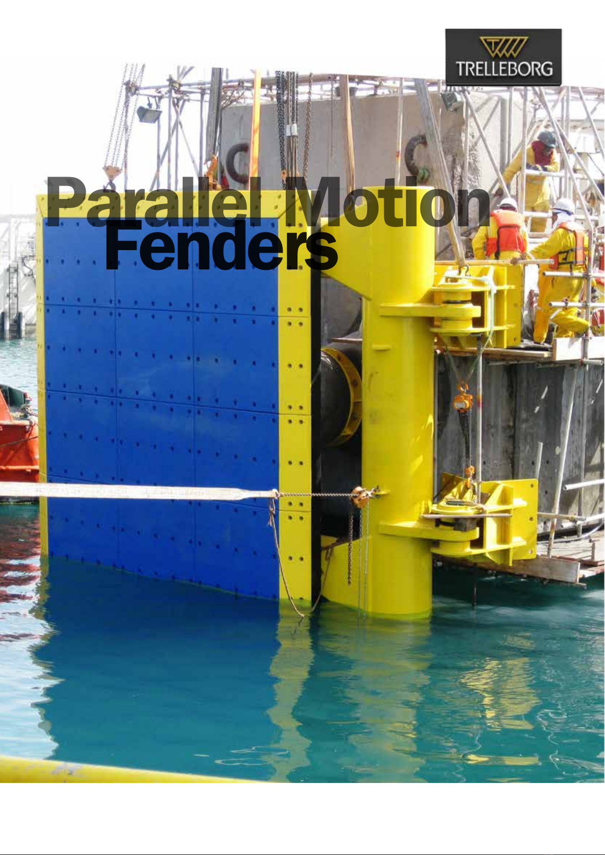
Trelleborg SCN 2250 Instruction Manual

TRELLEBORG MARINE AND INFRASTRUCTURE
Parallel Motion
Fenders
Handling, Storage, inStallation
and Maintenance Manual

1
Approach
The Smarter
Better connected systems mean faster
turnaround and increased throughput,
improved safety and lower operating costs.
Connecting decades of experience with a new, smarter
approach to port and terminal equipment optimization,
Trelleborg’s marine systems operation helps ports and
terminals deploy smart, engineered solutions for port
approach, berthing, docking and mooring. This enables
better informed real-time and strategic decision making,
both onshore and on board the vessel.
From port owners and operators to consulting engineers,
Trelleborg works with customers to determine best fit
solutions for specific applications, and supply a fully
integrated solution. End-to-end service and a
comprehensive product portfolio meet and exceed
customer needs, enhancing safety and improving
efficiency in all marine environments, from conception to
completion and beyond.
Transferring know-how
for smarter LNG
The smarter approach
for a more efficient port
Materials best practice
for a smarter port
The smarter approach
Connect with
The Smarter Approach
Visit: www.trelleborg.com/marineandinfrastructure
Connect: Trelleborg-Marine-and-Infrastructure
Discover: TrelleborgMarineandInfrastructure
Converse: @TrelleborgMI
Explore: Marineandinfrastructure
Discover: TrelleborgMarineandinfrastructure

2
PARALLEL MOTION FENDERS
HANDLING, STORAGE, INSTALLATION
AND MAINTENANCE MANUAL
Parellel Motion Fender System 5
Handling 9
Storage 11
Installation 13
Maintenance and Inspection 19
Appendix 21
References 23
Contents
Installation and
Handling, Storage,
Parallel Motion Fenders
Maintenance Manual
Trelleborg Marine Systems is a world leader
in the design and manufacture of advanced
marine fender systems.
We provide bespoke solutions for large and complex
projects all over the world. Best practice design and
quality materials ensure a long, low maintenance
service life, no matter how demanding the working
and environmental conditions.
All fenders are supplied fully tested and meet PIANC
2002 guidelines. Our pneumatic fenders are also
completely ISO17357-1:2014 compliant. Our high-
performance solutions combine low reaction force
and hull pressure with good angular performance
and rugged construction.
Trelleborg’s fender systems can be integrated with
SmartPort. SmartPort by Trelleborg is a technology
platform that connects disparate, data-driven
assets, giving stakeholders a holistic view of
operations to power communication and decision
making.
Take a Smarter Approach to fender performance
with Trelleborg.

3
A Smarter Approach
at every stage
Consultation
Conceptual design in your
local office – with full
knowledge of local standards
and regulations, delivered in
your language – for optimized
port and vessel solutions.
ConCepts
Concepts are taken to our
Engineering Centers of
Excellence where our team
generates 3D CAD designs,
application-engineering
drawings, a bill of materials,
finite engineering analyses
and calculations for both our
fender systems and marine
technology solutions.
DesiGn
Our entire product range
is manufactured in-house,
meaning we have full control
over the design and quality of
everything we produce. Our
strategically located, state-
of-the-art facilities ensure
our global, industry leading
manufacturing capability.
ManufaCture
A smarter approach to…
Consultation from the earliest
project phase to ensure the
optimum fender, mooring,
navigation and transfer
solutions are specified, with
full technical support from
our global offices.

4
When you choose Trelleborg you
ensure your expectations will be met,
because we deliver a truly end-to-end
service – retaining vigilance and full
control at every stage.
Dedicated project
management, from solution
design right the way through
to on-site installation support.
We design products and
solutions that always consider
ease of installation and future
maintenance requirements.
installation
Across our entire product
range, stringent testing
comes as standard at
every step in our in-house
manufacturing process. We
ensure that life-cycle and
performance of our entire
product range meets your
specifications, and more.
testinG
Local support on a truly global
scale, with customer support
teams all over the world. And
this service doesn’t stop after a
product is installed. You have our
full support throughout the entire
lifetime of your project, including
customized training programs,
maintenance and on-site service
and support.
support
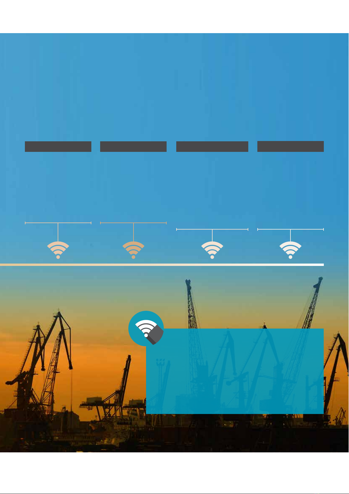
Deploying the latest in smart
technologies to enable fully
automated, data-driven
decision making that
optimizes port and terminal
efficiency. At Trelleborg, we’re
constantly evolving to provide
the digital infrastructure our
industry increasingly needs.
the future

5
Parallel Motion
Fender System
Parallel Motion Fender System keeps the panel vertical at all times – irrespective of where the impact loads
are applied – but simultaneously allows the panel to rotate on plan to accommodate large berthing angles.
Parallel Motion Fenders can absorb the full design energy irrespective of impact level.
As Parallel Motion Fenders are mostly pre-assembled in the factory, installation is simple and fast.
Maintenance is minimal too – contributing to the low service life cost of Parallel Motion technology.

6
1Rubber fender units
Shown here are two Super Cones mounted in a
back-to-back ‘Twin-Series’ configuration.
2Closed box panel (frame)
Fully sealed, pressure tested design. Shown with
optional lead-in bevels which are designed to suit
each case.
3Torsion tube and arm assembly
Also closed-box construction, the tube and arms
keep the panel vertical whatever level impact loads
are applied.
4Hinge units
The maintenance-free stainless steel pins and
bearings allow free rotation to accommodate berthing
angles, also eliminating moments in the hinge pin.
5UHMW-PE face pads
Trelleborg ‘Double Sintered’ UHMW-PE face pads
are standard to minimize friction and maximize
service intervals.
6Check chains (optional)
Check chains act as rope deflectors to stop ropes
from snagging, and to help with some large
angle berthings.
7Pile jackets (optional)
Purpose designed for every project, pile jackets are
factory built for a perfect fit to the fender onsite.
They can strengthen the structure and double as a
corrosion barrier in the vulnerable splash zone.
Jackets are also available for monopile systems.
1
2
3
4
6
7
5
Parallel Motion Fender System

7
Parallel Motion Fender System
PROVEN IN PRACTICE
Reverse mounted twin cone fender PMF system
installed on concrete structure
Standard mounted twin cone fender PMF system
installed on concrete structure
Reverse mounted twin cone fender PMF system
installed on steel pile
MV fender PMF system

8
Parallel Motion Fender System
PROVEN IN PRACTICE
Reverse mounted single cone fender PMF system
installed on concrete structure
MV fender PMF system

9
The Parellel Motion Fenders (PMF) unit will be delivered completely plastic wrapped and protected with
suitable paddings at the base and corners.
Handling

10
Handling
MATERIALS / CONSUMABLES REQUIRED INFORMATION
Timber / rubber blocks
After unloading, all the equipment must be placed on
timber / rubber blocks to avoid damage to the plastic
or painted surfaces.
EQUIPMENT REQUIRED INFORMATION
Crane Refer to the General Arrangement drawing for the total
weight of the equipment.
Rigging equipment with spreader beam Refer to the General Arrangement drawing for the total
weight of the equipment.
❙ Unwrap the plastic packaging of the PMF unit with
necessary tools
Caution
The unwrapping operation must be performed on
the truck trailer so that the lifting points are
exposed. Lifting point locations and sizes are subject
to change based on the project requirement. Refer
to the General Arrangement drawing for details.
❙ A Spreader beam of suitable length & load rating
must be used to lift the PMF unit from the truck
trailer.
Recommendation
In the event of non-availability of a spreader beam,
two separate lifting hooks can be used.
Caution
❙ Lifting rope angles must be set in a way that they
do not scrape off any painted surfaces. Paint
damage while lifting is not covered under warranty
& the damages must be repaired.
❙ Do not walk under suspended loads.the General
Arrangement drawing for details.
Figure 2: Unwraped PMF unit on truck trailer
Figure 3: Lifting the PMF unit with a Spreader beam

11
Storage
At all times, all equipment must be stored properly to avoid any damage, environmental damage or damage
occurring from nearby moving equipment.

12
Storage
PROCEDURES
❙ Timber / rubber blocks must be placed on a dry
surface and the PMF unit should be carefully
placed on the blocks.
❙ After successful placement of the PMF unit, cover
it with a waterproof plastic tarpaulin to protect it
from dust, direct sunlight and ambient moisture.
Recommendations
❙ Use medium-duty tarp with an approximate
thickness of 0.007 - 0.008 in (0.18 - 0.20 mm).
❙ For long-term storage (>6 months), use heavy-duty
tarp with an approximate thickness of 0.011 –
0.012 in (0.28–0.30 mm)
❙ The tarpaulin must be tightly bound using nylon
straps, making sure that there are no exposed
areas.
Caution
Do not place any equipment, tools or furniture over
the covered PMF unit.
MATERIALS / CONSUMABLES REQUIRED INFORMATION
Timber / rubber blocks
All equipment must be placed on timber / rubber
blocks to avoid damage to plastic or painted
surfaces.
Tarpaulin Heavy-duty waterproof plastic.
Figure 4: PMF unit placed on timber/ rubber blocks

13
Installation

14
Installation
2.1 FENDER TO STEEL PANEL
This section showcases the various steps involved for assembling the fender/fenders to the PMF unit.
MATERIALS / CONSUMABLES REQUIRED INFORMATION
Timber / rubber blocks The fender must be placed on timber / rubber blocks
to avoid any damage to the rubber body.
RECOMMENDED EQUIPMENT INFORMATION
General PPE As per site / plant requirements
EQUIPMENT REQUIRED INFORMATION
Fasteners Supplied by Trelleborg
Spanner Suitable to the supplied bolt size
2.1.1 SCN fenders to Steel Panel
Assembling SCN fenders
❙ Fix the ”first” fender on the spool.
❙ Align the Sandwich plate as shown on the image.
❙ Lower the ”second” fender on the Sandwich plate
such that the bolt holes are aligned.
❙ Insert and torque the bolts.
Recommendations
❙ After inserting the bolts, only turn enough to
ensure the threads are engaged and in line. Once
all bolts are loosely inserted and the holes are
aligned, tightening may be commenced. Firmly
fasten all bolts and then torque down, ensuring
that adjacent bolts are not tightened in sequence.
❙ For fastening to rubber, torque values from
Appendix A should be used.
❙ Standard bolt torque values should be used when
fastening to steel.
❙ Refer to MN-I&M-RUB-SCN&SCK-v1.0- EN, 2017
for fender lifting methods.
Caution
The “first” and “second” fenders must be identified
based on their grades prior to the commencement
of installation. Refer to the General Arrangement
drawing.
Figure 6: Assembling “back-to-back” SCN fenders
Sandwich
plate

15
Installation
2.1 FENDER TO STEEL PANEL
2.1.1 SCN fenders to Steel Panel
Installing ”back-to-back” SCN fenders on Steel
panel of the PMF unit
❙ The ”back-to-back” SCN fenders are to be fixed
with the fender spool as shown in the image.
❙ Insert and torque the bolts.
Recommendations
❙ After Inserting the bolts, only turn enough to
ensure the threads are engaged and in line. Once
all bolts are loosely inserted and the holes are
aligned, tightening may be commenced. Firmly
fasten all bolts and then torque down, ensuring
that adjacent bolts are not tightened in sequence.
❙ For fastening to rubber, torque values from
Appendix A should be used.
❙ Standard bolt torque values should be used when
fastening to steel.
❙ Refer to MN-I&M-RUB-SCN&SCK-v1.0- EN, 2017
for fender lifting methods.
Installing MV fenders
❙ Place the frontal frame face down to the ground,
supported on timbers.
❙ Place and align the rubber fender holes with
ferrules of the steel panel.
❙ Insert and torque the bolts.
Recommendations
❙ After Inserting the bolts, only turn enough to
ensure the threads are engaged and in line. Once
all bolts are loosely inserted and the holes are
aligned, tightening may be commenced. Firmly
fasten all bolts and then torque down as required.
❙ Standard bolt torque values should be used when
fastening to steel.
❙ Refer to MN-I&M-RUB-MV&UE-v1.0-EN, 2017 for
fender lifting methods.
Figure 7: Installing “back-to-back”
SCN fenders on steel panel of the PMF unit
Figure 8: Installing MV/UE fenders
on steel panel of the PMF unit

16
Installation
2.2 PMF UNIT TO STRUCTURE
This section showcases the various steps involved for installing the PMF unit to concrete.
MATERIALS / CONSUMABLES REQUIRED INFORMATION
Timber / rubber blocks The PMF must be placed on timber / rubber blocks
to avoid any damage to the rubber body.
RECOMMENDED PERSONAL PROTECTIVE
EQUIPMENT INFORMATION
General PPE As per site / plant requirements
EQUIPMENT REQUIRED INFORMATION
Fasteners Supplied by Trelleborg
Spanner Suitable to the supplied bolt size
2.2.1 Installation on concrete structure
❙ Unfasten ropes which connect the mounting
brackets to the torsion tube.
❙ Identify the top side and orientation of the steel
panel from the General Arrangement drawing.
❙ Fasten the lifting brace with two lifting points on
the top side of the steel panel as shown in the
image. Rotate the torsion arms and fix the third
lifting point with the lifting brace.
Figure 9: Lifting brace installation on PMF
Lifting points
Lifting brace

17
Installation
2.2 PMF UNIT TO STRUCTURE
2.2.1 Installation on concrete structure
❙ Pivot the PMF unit and position it in vertical
orientation.
❙ Move PMF unit to the structure where it is to be
installed with the assistance of a crane.
❙ Align the fender / spool holes with the anchor
location on concrete.
❙ Fasten the fender with the supplied hardware
shown in the general arrangement and anchor
layout drawings.
Recommendations
❙ Use the standard bolt torque values when fastening
to the steel.
❙ Use torque values from Appendix A when fastening
to fender.
For anchor installations refer to MN-I&MANCHOR-
v1.0-EN, 2017
❙ Locate the torsion arm brackets on the anchor
locations.
❙ Fix the brackets with the supplied fasteners shown
in the general arrangement and anchor layout
drawings.
Figure 10: PMF unit assembly lifting

18
Installation
2.2 PMF UNIT TO STRUCTURE
2.2.2 Installation on steel pile
Figure 11: Typical installation on steel pile
RECOMMENDED PERSONAL PROTECTIVE
EQUIPMENT INFORMATION
General PPE As per site / plant requirements
EQUIPMENT REQUIRED INFORMATION
Fasteners Supplied by Trelleborg
While installing on steel pile:
Mounting of the hole locations and connecting plate
sizes of the pile structure must be in accordance to
the approved anchor layout drawing.
Recommendations
❙ Use the standard bolt torque values when fastening
to the steel.
❙ Use torque values from Appendix A when fastening
to fender.

19
Maintenance and
Inspection
This manual suits for next models
20
Table of contents
Other Trelleborg Industrial Equipment manuals