WIKA DSSA11SA User manual

Operating instructions
Betriebsanleitung
EN
DE
Examples of model DSSA11A
Compact diaphragm seal system, hygienic design, with
IO-Link and switching outputs, model DSSA11SA
Kompakt-Druckmittlersystem, Hygienic Design, mit IO-Link und
Schaltausgängen, Typ DSSA11SA

2
14543105.01 08/2023 EN/DE
WIKA operating instructions, model DSSA11A
EN
DE
© 08/2023 WIKA Alexander Wiegand SE & Co. KG
All rights reserved. / Alle Rechte vorbehalten.
WIKA®is a registered trademark in various countries.
WIKA®ist eine geschützte Marke in verschiedenen Ländern.
Prior to starting any work, read the operating instructions!
Keep for later use!
Vor Beginn aller Arbeiten Betriebsanleitung lesen!
Zum späteren Gebrauch aufbewahren!
Operating instructions, model DSSA11A Page 3 - 30
Betriebsanleitung, Typ DSSA11A Seite 31 - 58

3WIKA operating instructions, model DSSA11SA
EN
14543105.01 08/2023 EN/DE
Contents
Contents
1. General information 5
1.1 Abbreviations, definitions . . . . . . . . . . . . . . . . . . . . . . 6
1.2 Explanation of symbols . . . . . . . . . . . . . . . . . . . . . . . 6
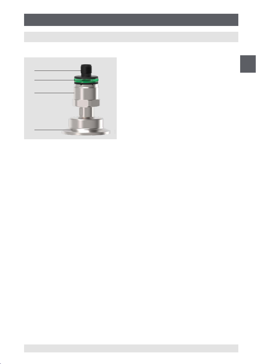
2. Design and function 7
2.1 Overview, diaphragm seal system . . . . . . . . . . . . . . . . . . . 7
2.2 Description . . . . . . . . . . . . . . . . . . . . . . . . . . . 7
2.3 Scope of delivery . . . . . . . . . . . . . . . . . . . . . . . . . 8
2.4 Product passport . . . . . . . . . . . . . . . . . . . . . . . . . 8
3. Safety 8
3.1 Intended use. . . . . . . . . . . . . . . . . . . . . . . . . . . 8
3.2 Improper use . . . . . . . . . . . . . . . . . . . . . . . . . 10
3.3 Responsibility of the operator . . . . . . . . . . . . . . . . . . . . 10
3.4 Personnel qualification . . . . . . . . . . . . . . . . . . . . . . 11
3.5 Use of accessories and spare parts . . . . . . . . . . . . . . . . . . 11
3.6 Labelling, safety marks . . . . . . . . . . . . . . . . . . . . . . 12
3.7 Compliance with 3-A conformity . . . . . . . . . . . . . . . . . . . 12
3.8 Compliance with EHEDG conformity . . . . . . . . . . . . . . . . . 12
4. Transport, packaging and storage 13
4.1 Transport . . . . . . . . . . . . . . . . . . . . . . . . . . . 13
4.2 Packaging . . . . . . . . . . . . . . . . . . . . . . . . . . 13
4.3 Storage . . . . . . . . . . . . . . . . . . . . . . . . . . . 13
5. Commissioning, operation 14
5.1 General mounting instructions. . . . . . . . . . . . . . . . . . . . 14
5.2 Mounting instructions for diaphragm seal systems with 3-A and EHEDG . . . . . 14
5.3 Requirements for mounting point . . . . . . . . . . . . . . . . . . . 14
5.4 Mechanical mounting. . . . . . . . . . . . . . . . . . . . . . . 15
5.5 Electrical mounting . . . . . . . . . . . . . . . . . . . . . . . 16
5.6 Teach function (if available). . . . . . . . . . . . . . . . . . . . . 16
5.7 Colour codes of the 360° LED status indication . . . . . . . . . . . . . . 17
5.8 Switching functions . . . . . . . . . . . . . . . . . . . . . . . 18
5.9 Damping function (0 ... 65 s) (configurable via IO-Link) . . . . . . . . . . . 19
5.10 Zero point setting . . . . . . . . . . . . . . . . . . . . . . . . 19
5.11 Description of the IO-Link functionality . . . . . . . . . . . . . . . . . 19
5.12 Commissioning . . . . . . . . . . . . . . . . . . . . . . . . . 19
6. Faults 20
7. Cleaning, maintenance and recalibration 21
7.1 Exterior cleaning of the diaphragm seal system . . . . . . . . . . . . . . 21
7.2 Cleaning of the diaphragm . . . . . . . . . . . . . . . . . . . . . 22
7.3 Cleaning in place (CIP) cleaning process . . . . . . . . . . . . . . . . 22
7.4 Maintenance. . . . . . . . . . . . . . . . . . . . . . . . . . 22
7.5 Recalibration . . . . . . . . . . . . . . . . . . . . . . . . . 22

4WIKA operating instructions, model DSSA11SA
EN
14543105.01 08/2023 EN/DE
Declarations of conformity can be found online at www.wika.com
8. Dismounting, return and disposal 23
8.1 Dismounting . . . . . . . . . . . . . . . . . . . . . . . . . . 23
8.2 Return . . . . . . . . . . . . . . . . . . . . . . . . . . . . 23
8.3 Disposal . . . . . . . . . . . . . . . . . . . . . . . . . . . 24
9. Specifications 25
10. Accessories 29
Annex 1: Default values 30
Contents

5WIKA operating instructions, model DSSA11SA
EN
14543105.01 08/2023 EN/DE
Contents
1. General information
■The instrument described in the operating instructions has been designed and
manufactured using state-of-the-art technology. All components are subject to strin-
gent quality and environmental criteria during production. Our management systems
are certified in accordance with ISO 9001 and ISO 14001.
■These operating instructions contain important information on handling the diaphragm
seal system. Working safely requires that all safety instructions and work instructions
are observed.
■Observe the relevant local accident prevention regulations and general safety regula-
tions for the instrument's range of use.
■The operating instructions are part of the product and must be kept in the immediate
vicinity of the instrument and readily accessible to skilled personnel at any time. Pass
the operating instructions on to the next operator or owner of the instrument.
■Skilled personnel must have carefully read and understood the operating instructions
prior to beginning any work.
■In case of a different interpretation of the translated and the English operating instruc-
tions, the English wording shall prevail.
■The general terms and conditions contained in the sales documentation shall apply.
■Subject to technical modifications.
Further information:
- Website: www.wika.de/www.wika.com
- Relevant data sheet: DS 95.25
Supplementary documentation:
▶Please follow all the documentation included in delivery.

6WIKA operating instructions, model DSSA11SA
EN
14543105.01 08/2023 EN/DE
1. General information
1.1 Abbreviations, definitions
■Bullet
▶Instruction
1. ... x. Follow the instruction step by step
⇒Result of an instruction
→See ... Cross reference
1.2 Explanation of symbols
WARNING!
... indicates a potentially dangerous situation that can result in serious injury
or death, if not avoided.
CAUTION!
... indicates a potentially dangerous situation that can result in light injuries or
damage to property or the environment, if not avoided.
DANGER!
... identifies hazards caused by electrical power. Should the safety instructions
not be observed, there is a risk of serious or fatal injury.
WARNING!
... indicates a potentially dangerous situation that can result in burns, caused
by hot surfaces or liquids, if not avoided.
Information
... points out useful tips, recommendations and information for efficient and
trouble-free operation.

7WIKA operating instructions, model DSSA11SA
EN
14543105.01 08/2023 EN/DE
2. Design and function
2.1 Overview, diaphragm seal system
2.2 Description
The flush diaphragm at the process connection of the diaphragm seal system transmits
the process pressure via a system fill fluid to the pressure sensor. The model DSSA11SA
diaphragm seal system is available in different versions.
■1 or 2 PNP/NPN switch points
■With additional IO-Link interface or teach function for switch points
■3 case designs
– Circular connector M12 x 1 with or without 360° LED status indication
– Circular connector M12 x 1, metal version
– Angular connector DIN 175301-803 A with or without 360° LED status indication
In the basic version, the instrument is fitted with a pressure sensor without a display,
which, depending on the application, can be used either for pressure monitoring or as an
electronic PNP/NPN switch for process control.
With an additional IO-Link interface, the instrument can be programmed flexibly and has
integrated diagnostic functions that monitor the instrument status. In addition, this allows
the digital signal to be configured externally and conveniently at any time.
This version, which has been enhanced with a 360° LED status indication, provides visual
information about the status and enables intuitive and quick error detection and correc-
tion. For maintenance, a blinking function via IO-Link facilitates the clear localisation of a
diaphragm seal system.The blinking function prevents confusion of measuring locations
and accelerates maintenance.
In addition to the IO-Link, the teach function enables a further on-site configuration of the
switch point if a convenient factory setting of the point is not possible.
2. Design and function
Electrical connection (depending on version)
360° LED status indication (depending on version)
Pressure sensor integrated into case
TRI-CLAMP®process connection (depending on
version)

8WIKA operating instructions, model DSSA11SA
EN
14543105.01 08/2023 EN/DE
A customer-specific switch point setting can be defined when ordering. If no additional
ordering information is provided, the factory setting is set for switching at the full scale
value and for switching back at 90 % of the full scale value.The switch point setting can
only be subsequently parameterised for diaphragm seal systems with an IO-Link interface
or teach function.
2.3 Scope of delivery
■Diaphragm seal system
■Operating instructions
■Certificates (option)
Cross-check scope of delivery with delivery note.
2.4 Product passport
The product passport is a web application where various information about an instrument
can be retrieved by entering the 11-digit alphanumeric serial number. This includes, for
example, instrument configuration, article number, operating instructions, data sheet or
calibration certificates.The product passport can be retrieved from the product page or
directly from the corresponding web application (https://portal.wika.com/serial/).
Web application
3. Safety
3.1 Intended use
The model DSSA11SA diaphragm seal system is used on the one hand for the
pressure-dependent switching of circuits by means of a PNP or NPN output signal for
process control. Moreover, versions with standardised IO-Link interfaces can easily
be configured and the instrument status can be monitored. Depending on the selected
measuring range, the instrument can be used for measuring gauge pressure/vacuum or
absolute pressure.
The compact instrument has been designed for industrial hygienic applications (for
indoor and outdoor areas).The all-welded diaphragm ensures a long service life and leak
tightness.The requirements of CIP (cleaning in place) and SIP (sterilisation in place) are
fulfilled. Process connection and system fill fluid are suitable for the food and pharma-
ceutical industry and, depending on the version, are available for applications with 3-A or
EHEDG requirements.
2. Design and function / 3. Safety

9WIKA operating instructions, model DSSA11SA
EN
14543105.01 08/2023 EN/DE
WARNING!
Physical injuries and damage to property and the environment through
exceeding the performance limits
Exceeding the performance limits can destroy the instrument and lead to
danger in the end-use application.
▶Only use the instrument in applications that lie within its technical perfor-
mance limits. Only operate the instrument with media that cannot damage
the wetted parts.
→ For performance limits, see product label of the instrument and chapter 9
“Specifications”
▶Any permanent operation in the overload range is not permissible. Above
the end of measuring range, up to the overpressure limit, the instrument
is operating outside its specification.This pressure range is intended to
prevent damage to the instrument, as part of a pressure vessel system,
during the pressure containment test.
▶The overpressure limit must never be exceeded, even when failures occur
in the end-use application. Loads above the overpressure limit can cause
irreversible damage, which can lead, for example, to safety or permanent
measured errors.When the overpressure limit is exceeded, the instrument
must be replaced.
▶The manufacturer or operator of the machine or plant in which the product
is used must ensure the compatibility of the materials of the wetted parts
with the medium used.
▶Do not use the instrument with highly viscous, abrasive and aggressive
media.
▶The electrical hazards specified in chapter 5 “Commissioning, operation”
have to be taken into account.
▶The instrument is not permitted to be used in hazardous areas!
▶After an external fire (generation of heat, direct flame impingement, smoke
or heat radiation), the instrument must be replaced or sent to WIKA for
inspection.
The (dis)mounting, installation, parameterisation and maintenance of the DSSA11SA in
industrial environments absolutely requires suitably skilled personnel in accordance with
chapter 3.4 “Personnel qualification”.
Pressure surges below the nominal pressure and shorter than 1 ms can cause
measured errors.
The instrument has been designed and built solely for the intended use described here,
and may only be used accordingly. No separation into its components is permissible.
The technical specifications contained in these operating instructions must be observed.
3. Safety

10 WIKA operating instructions, model DSSA11SA
EN
14543105.01 08/2023 EN/DE
After exceeding the specification limits or in case of visible changes to the instrument, this
must be stopped immediately and checked by an authorised WIKA service engineer.The
manufacturer shall not be liable for claims of any type based on operation contrary to the
intended use.
Should the operating instructions not be observed or complied with, approvals (e.g.
EHEDG) can become invalid.
3.2 Improper use
WARNING!
Injuries through improper use
Improper use of the instrument can lead to hazardous situations and injuries.
▶Refrain from unauthorised modifications/repairs to the instrument.
▶Do not use the instrument as part of a safety device for protection against
exceeding permissible limits (safety accessory).
▶The instrument must not be used as a climbing aid.
Any use beyond or different to the intended use (see chapter 3.1) is considered as
improper use.
3.3 Responsibility of the operator
The instrument is used in the industrial sector.The operator is therefore responsible for
legal obligations regarding safety at work.
The safety instructions within these operating instructions, as well as the safety, accident
prevention and environmental protection regulations for the application area must be
maintained.
The operator is obliged to maintain the product label in a legible condition.
To ensure safe working on the instrument, the operating company must ensure
■that the instrument is suitable for the particular application in accordance with its
intended use.
■that the instrument is only used in applications that lie within its technical performance
limits (e.g. max. ambient temperature, material compatibility, ...).
■that the compatibility between the wetted parts, the medium and the environment is
ensured.
■that the requisite personal protective equipment is provided.
3. Safety

11WIKA operating instructions, model DSSA11SA
EN
14543105.01 08/2023 EN/DE
3.4 Personnel qualification
WARNING!
Risk of injury should qualification be insufficient
Improper handling can result in considerable injury and damage to property.
▶The activities described in this document may only be carried out by skilled
personnel who have the qualifications described below.
Skilled personnel
Skilled personnel, authorised by the operator, are understood to be personnel who,
based on their technical training, knowledge of measurement and control technology and
on their experience and knowledge of country-specific regulations, current standards and
directives, are capable of carrying out the work described and independently recognising
potential hazards.
Skilled electrical personnel
Skilled electrical personnel are understood to be personnel who, based on their techni-
cal training, know-how and experience as well as their knowledge of country-specific
regulations, current standards and directives, are capable of carrying out work on electri-
cal systems and independently recognising and avoiding potential hazards.The skilled
electrical personnel have been specifically trained for the work environment they are
working in and know the relevant standards and regulations.The skilled electrical person-
nel must comply with current legal accident prevention regulations.
Special operating conditions require further appropriate knowledge.
3.5 Use of accessories and spare parts
It is recommended to use original accessories and original spare parts from WIKA. Using
accessories and spare parts from third parties can lead to damage to the instrument or
accidents, due to quality defects or other reasons.
WIKA assumes no liability for damage or accidents caused by a malfunction or unsuitabil-
ity of accessories and spare parts which do not originate from WIKA (e.g. non-compliance
with the IP ingress protection of connectors). No warranty claims can be made which
arise due to a malfunction or unsuitability of any accessory or spare part from a third
party.
3. Safety

12 WIKA operating instructions, model DSSA11SA
EN
14543105.01 08/2023 EN/DE
3.6 Labelling, safety marks
Diaphragm seal
The diaphragm seal is marked with the material code and the mark of the person author-
ised for restamping.
Product label
Model + code of the hygienic certification i# serial number
Without code = without hygienic certification Additional text
Code “H” = 3-A-compliant → See chapter 3.7 Measuring range
Code “E” = EHEDG-certified Coded date of manufacture
→See chapter 3.8 Pin assignment and specifications
IO-Link (if available) Approvals
P# product number
If the serial number becomes illegible (e.g. due to mechanical damage or overpainting),
traceability will no longer be possible.
Symbols
Before mounting and commissioning the instrument, ensure you read the
operating instructions!
Do not dispose of with household waste. Ensure a proper disposal in
accordance with national regulations.
3.7 Compliance with 3-A conformity
For a 3-A-compliant connection, seals in accordance with standards have to be used.
For compliance with conformity in accordance with 3-A standards, only the version with
circular connector M12 x 1, metal version, is permissible.
Compliance with conformity is only given for versions that are marked with the 3-A
logo in the data sheet. 3-A-compliant diaphragm seal systems are marked as model
DSSA11SA-H on the product label.
→ For further information, see data sheet DS 95.25.
3.8 Compliance with EHEDG conformity
For an EHEDG-compliant connection, seals in accordance with the current EHEDG
policy document must be used.
Seals for connections per DIN 32676 and BS 4825 part 3 are, e.g., manufactured by
DE-63911 Klingenberg Made in Germany
3. Safety

13WIKA operating instructions, model DSSA11SA
EN
14543105.01 08/2023 EN/DE
Combifit International B.V.
The three possible case designs fulfil the criteria of the EHEDG approvals and are
approved for the hygienic industry in accordance with the appropriate standard.
Compliance with conformity is only given for certified versions that are marked with the
EHEDG logo in the data sheet. EHEDG-compliant diaphragm seal systems are marked
as model DSSA11SA-E on the product label.
→ For further information, see data sheet DS 95.25.
4. Transport, packaging and storage
CAUTION!
Damage through improper transport
With improper transport, a high level of damage to property can occur.
▶When unloading packed goods upon delivery as well as during
internal transport, proceed carefully and observe the symbols on the
packaging.
▶With internal transport, observe the instructions in the following
chapters
4.1 Transport
Check the instrument for any damage that may have been caused by transport. Obvious
damage must be reported immediately.
4.2 Packaging
Do not remove packaging until just before mounting.
Keep the packaging as it will provide optimum protection during transport (e.g. change in
installation site, return).
4.3 Storage
Permissible conditions at the place of storage:
■Storage temperature: -35 ... +70 °C [-31 ... +158 °F]
Avoid exposure to the following factors:
■Proximity to hot objects, when permissible storage temperature is exceeded by
radiation.
■Mechanical vibration, mechanical shock (putting it down hard), when the permissible
values are exceeded, see chapter 9 “Specifications”.
■Soot, vapour, dust and corrosive gases.
■Hazardous environments, flammable atmospheres
3. Safety / 4.Transport, packaging and storage

14 WIKA operating instructions, model DSSA11SA
EN
14543105.01 08/2023 EN/DE
Store the instrument in its original packaging in a location that fulfils the conditions listed
above. If the original packaging is not available, then store the instrument in a container
that is similar to the original packaging, so that the instrument can't be scratched and is
protected against damage if dropped.
5. Commissioning, operation
Only use the instrument if it is in perfect condition with respect to safety.
5.1 General mounting instructions
Prior to commissioning, the instrument must be subjected to a visual inspection.
■Check the diaphragm for scratches and damage.
■Leaking liquid is indicative of damage.
■Sealed screws must not be loosened under any circumstances. Otherwise there is a
risk that the system fill fluid may escape, with the result that the measuring assembly
may not function correctly anymore.
■Check the seal for contamination and damage and clean or replace it, if necessary.
■Check the sealing faces for contamination and damage and clean or rework them, if
necessary.
5.2 Mounting instructions for diaphragm seal systems with 3-A and EHEDG
Observe the following instructions, especially for EHEDG-certified and 3-A-compliant
diaphragm seal systems.
■Make sure that the conditions described in chapter 3.7 “Compliance with 3-A conform-
ity” are fulfilled for diaphragm seal systems with 3-A.
■Make sure that the conditions described in chapter 3.8 “Compliance with EHEDG
conformity” are fulfilled for diaphragm seal systems with EHEDG.
■Mount the instrument with minimal dead space and able to be cleaned easily.
■The mounting position must not form a draining point or cause a basin to be formed.
5.3 Requirements for mounting point
The mounting point must meet the following conditions:
■Protected from weather influences. Permanent exposure to UV light/sunlight can lead
to a change in the colour of the plastic parts and a clouding/yellowing of the status
indication.Therefore, a possible restriction of the visibility of the status indication
cannot be excluded.
■Under corrosive ambient conditions (e.g. salty, humid air), restrictions in the gloss level
of the metal surfaces, or even corrosion on the instrument, may occur, which make
readability of the product label more difficult.
■Sealing faces and seals are clean and undamaged.
5. Commissioning, operation

15WIKA operating instructions, model DSSA11SA
EN
14543105.01 08/2023 EN/DE
■Sufficient space for a safe electrical installation.
■The instrument is vented to the atmosphere.Therefore, no coating or other covering
may be applied which might restrict the venting.
5.4 Mechanical mounting
The instrument may only be installed and mechanically mounted by skilled personnel.
Mounting is only permissible in the depressurised state. Reliably depressurise the
process connection using the available valves and protective devices (e.g. shut-off valve,
monoflange).
WARNING!
Physical injuries and damage to property and the environment caused
by hazardous media
Upon contact with hazardous media (e.g. oxygen) and also with refrigeration
plants and compressors, there is a danger of physical injuries and damage to
property and the environment.
Media with extremely high temperature and under high pressure or vacuum
may be present at the instrument.
▶For these media, in addition to all standard regulations, the appropriate
existing codes or regulations must also be followed.
▶Wear the requisite protective equipment.
WARNING!
Risk of burns
On opening the process connection, there is a risk of dangerously hot media
escaping.
▶Let the process connection cool down sufficiently before installing it!
The installation of the instrument must be carried out in accordance with the specifica-
tions of the respective process connection. Other installation types, e.g. direct welding,
are not permissible and are considered as improper use.
■Remove the protective cap of the instrument not until shortly before installation.
■Avoid any contact with or mechanical loading of the diaphragm. Scratches on the
diaphragm (e.g. from sharp-edged objects) are the main causes of corrosion.
■Seal the process connection.
- Select a suitable seal.
- Centre sealing on the sealing face.
- The diaphragm movement must not be limited due to the sealing.
■Use appropriate clamps for the existing clamp connection and mount them in accord-
ance with manufacturer's instructions.
5. Commissioning, operation

16 WIKA operating instructions, model DSSA11SA
EN
14543105.01 08/2023 EN/DE
5.5 Electrical mounting
The activities described in this chapter may only be carried out by skilled electrical
personnel.
5.5.1 Requirements for voltage supply
This equipment is intended for operation with low voltages, which are separated from
the AC 230 V (50 Hz) mains voltage – or voltages greater than AC 50 V or DC 120 V for
dry environments. A connection to an SELV circuit is recommended, or alternatively to
circuits with a different protective measure in accordance with IEC 60364-4-41 installation
standard.
5.5.2 Requirements for electrical connection
■Ingress protection of the mating connector corresponds to the ingress protection of the
instrument.
■Cable diameter matches the cable bushing of the mating connector.
■Cable gland and seals of the mating connector are correctly seated.
■No moisture can ingress at the cable end.
5.5.3 Requirement for shield and grounding
The instrument must be grounded via the process connection.
When working during a running process operation, measures to prevent electrostatic
discharge on the connection terminals should be taken, as a discharge could lead to
temporary corruption of the measured value.
5.5.4 Connecting the instrument
1. Assemble the mating connector or cable outlet.
→ For pin assignment see product label
2.Establish the plug connection.
5.6 Teach function (if available)
With the teach function, the instrument can be configured by short-circuiting the teach pin
with U-.
Setting the switch point and the window
To adopt the prevailing process pressure as a new switch point or high value (window).
Short-circuit the teach pin with U- for 2 ... 5 seconds.
5. Commissioning, operation

17WIKA operating instructions, model DSSA11SA
EN
14543105.01 08/2023 EN/DE
▶Blinking yellow:Teach mode for switch point active, remove short-circuit.
▶Blinking green: New switch point adopted.
▶Blinking red:Teach pin not short-circuited for long enough or error in teach process.
The reset point and the low value for the window function will be corrected
automatically. The previously set hysteresis (for default value, see Annex 1
“Default values”) or the difference between the window high and window low
will be restored. In the event that the prevailing pressure is below 5 % of the
full scale value, no teach process will be carried out. Should the prevailing
pressure be less than the set hysteresis or the set window band, the reset
point or the low value of the window function will be set to the start of measu-
ring range.
Setting the switching function
To change the switching function between normally open and normally closed.
Short-circuit the teach pin with U- for 10 ... 20 seconds.
▶2 ... 5 seconds: Blinking yellow: Teach mode for switch point active, do not remove
short-circuit.
▶5 ... 10 seconds: Permanently lit yellow:Teach mode changes to switching function, do
not remove short-circuit.
▶10 ... 20 seconds: Blinking yellow: Teach mode for switching function active, remove
short-circuit.
▶> 20 seconds: Permanently lit yellow, teach process failed.
▶Blinking green: Switching function changed.
▶Blinking red:Teach pin not short-circuited for long enough or error in teach process.
5.7 Colour codes of the 360° LED status indication
Colour Interval Description
Green Lit permanently Instrument is ready for operation, no error
Blinking (5 seconds) Teach successful
Yellow Blinking (continuously) Temporary error, operation outside of the specication (e.g.
under- or overpressure, under- or overtemperature).
Lit permanently Time exceeded, teach signal applied longer than 20 s
Blinking (during teach) Instrument blinks so long as the teach is running
Red Blinking (continuously) “Locate me” function active or permanent error; In case of a
permanent error, the instrument must be replaced
Blinking (5 seconds) Teach failed
5. Commissioning, operation

18 WIKA operating instructions, model DSSA11SA
EN
14543105.01 08/2023 EN/DE
5.8 Switching functions
Hysteresis function (configurable via teach function or IO-Link)
If the system pressure fluctuates around the set point, the
hysteresis keeps the switching status of the outputs stable.
With increasing system pressure, the output switches when
reaching the switch point (SP).
■Normally open contact (HNO): Active
■Normally closed contact (HNC): Inactive
With system pressure falling again, the output will not switch
back before the reset point (RP) is reached.
■Normally open contact (HNO): Inactive
■Normally closed contact (HNC): Active
Window function (configurable via teach function or IO-Link)
The window function allows for the control of a defined
range.
When the system pressure is between window high (FH)
and window low (FL), the output switches on.
■Normally open contact (FNO): Active
■Normally closed contact (FNC): Inactive
When the system pressure is outside window high (FH) and
window low (FL), the output does not switch on.
■Normally open contact (FNO): Inactive
■Normally closed contact (FNC): Active
Adjustability:
■Switch point/window high
The value must be higher than the reset point or window low. The minimum difference
is 0.25 % of the measuring range.With a setting less than 0.25 %, the reset point will be
adjusted automatically.
■Reset point/window low
The value must be lower than the switch point or window high.The minimum difference
is 0.25 % of the measuring range.With a setting less than 0.25 %, the switch point will
be adjusted automatically.
Fig.: Hysteresis function
Fig.: Window function
5. Commissioning, operation

19WIKA operating instructions, model DSSA11SA
EN
14543105.01 08/2023 EN/DE
Delay times (0 … 65 s) (configurable via IO-Link)
This makes it possible to filter out unwanted pressure spikes
of a short duration or a high frequency.
The pressure must be present for at least a certain preset
time for the output to switch on.The output does not immedi-
ately change its status when it reaches the switching event
(SP), but rather only after the preset delay time (DS).
The output only switches back when the system pressure
has fallen down to the reset point (PR) and stays at or below
the reset point (RP) for at least the preset delay time (DR).
If the switching event is no longer present after the delay
time, the switch output does not change.
5.9 Damping function (0 ... 65 s) (configurable via IO-Link)
With this, the time span between a pressure change and the change of the switching
status can be set.
5.10 Zero point setting
A zero point offset can be reset with the 0SET parameter via IO-Link. Only carry out zero
point setting for gauge and vacuum pressure measuring ranges at the start of the measu-
ring range.
Carry out the zero point setting of absolute pressure measuring ranges at
0 bar absolute (vacuum). Since appropriate references are required for this,
we recommend that this is only carried out by the manufacturer.
5.11 Description of the IO-Link functionality
IO-Link specification: Version 1.1
IO-Link is a point-to-point connection for the communication of the instrument with an
IO-Link master.
The IO-Link communication allows you to transmit the pressure and
switch point status in digital form. Furthermore, IO-Link offers the possibility to configure,
control and monitor the system status using the integrated diagnostic function.Thanks to
a standardised device description file (IODD), the software required for this can be freely
selected by the user independently of manufacturer.
A detailed description of the IO-Link functionality and the device description file (IODD)
can be found online on the product details page at .www.wika.com.
5.12 Commissioning
During the commissioning process pressure surges must be avoided at all costs. Open
the shut-off valves slowly.
Fig.: Delay times
5. Commissioning, operation

20 WIKA operating instructions, model DSSA11SA
EN
14543105.01 08/2023 EN/DE
6. Faults
CAUTION!
Physical injuries and damage to property and the environment
If faults cannot be eliminated by means of the listed measures, the instrument
must be taken out of operation immediately.
▶Ensure that pressure or signal is no longer present and protect against
accidental commissioning.
▶Contact the manufacturer.
▶If a return is needed, please follow the instructions given in chapter 8
“Dismounting, return and disposal”.
WARNING!
Physical injuries and damage to property and the environment caused
by hazardous media
Upon contact with hazardous media (e.g. oxygen) and also with refrigeration
plants and compressors, there is a danger of physical injuries and damage to
property and the environment.
▶Should a failure occur, media with extremely high temperature and under
high pressure or vacuum may be present at the instrument.
▶For these media, in addition to all standard regulations, the appropriate
existing codes or regulations must also be followed.
▶Wear the requisite protective equipment.
For contact details, see chapter 1 “General information” or the back page of
the operating instructions.
In the event of any faults, first check whether the instrument is mounted correctly,
mechanically and electrically.
If complaint is unjustified, the handling costs will be charged.
Fault Possible cause Measure
No output signal Cable break Check the continuity
No/wrong auxiliary power Correct the auxiliary power
No/wrong output signal Wiring error or switching of
switching logic
Observe the pin assignment
Check the output conguration
Constant output signal
upon change in pressure
Mechanical overload caused by
overpressure
Replace instrument; if it
fails repeatedly, contact the
manufacturer
Deviating zero point
signal
Overload safety exceeded Observe the permissible
overload safety
6. Faults
Table of contents
Languages:
Other WIKA Industrial Equipment manuals