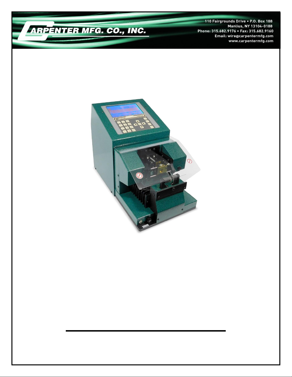
Carpenter Model 75 Compu-Strip®
Carpenter Model 75 Compu-Strip®•Phone: (315) 682-9176 • Fax: (315) 682-9160
Website: www.carpentermfg.com • Email: wire@carpentermfg.com
Revised June 10th, 2019 Page 4
Introduction
Thank you for choosing Carpenter Mfg. Co., Inc. for your wire processing equipment
needs. For over 60 years Carpenter has been a leader in wire processing technology
and service. As an independently-owned, third generation company our philosophy has
always been to provide the customer with both quality products and outstanding service.
We look forward to a long, healthy relationship with you and our company.
Every attempt has been made during the development of this operator’s manual to
include all relevant information pertaining to the operation and maintenance of the
Model 75 Compu-Strip® in an easy-to-read and easy-to-apply format. However, the
Model 75 is a complex piece of equipment and certain inaccuracies or typographical
errors may inadvertently be contained within these pages. Carpenter Mfg. Co., Inc.
shall not be held liable for these errors. We welcome customer input concerning this
operator’s manual. If you should find an error or have a suggestion on how this manual
could be enhanced, please feel free to contact us. Our phone number is (315) 682-
9176; we may also be reached by fax at (315) 682-9160. Visit our website
The Model 75 is a fully programmable wire and coaxial cable stripper that is designed to
strip a wide range of wire and cables, as referenced on the following pages. A great
amount of work has gone into the development of the Model 75, in order to offer a
product that is universally applicable to stripping the many varied types of cables within
its range of specifications. There may, however, be cables that fall within the Model 75
operating range that do not process satisfactorily on the Model 75. This may be due to
many factors, including but not limited to, cable construction, poor cable/material quality,
and/or required strip specifications. To determine if the Model 75 will satisfactorily
perform the stripping requirements, Carpenter Mfg. Co., Inc. strongly recommends a
free wire evaluation, to be completed at our factory (http://carpentermfg.com/wire-
evaluation/). A demonstration from a Carpenter representative is also recommended to
ensure the ultimate success of your wire processing application.
This operating manual explains how to operate the Model 75 Compu-Strip®. To ensure
the best performance of your machine, read this manual carefully until you familiarize
yourself thoroughly with its operation and features. After you have read through the
manual, keep it available for reference.
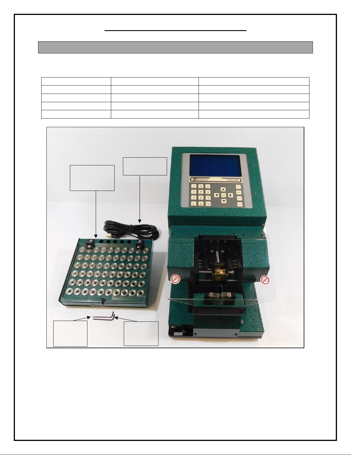
Carefully unpack the Carpenter Model 75 Compu-Strip®. We recommend that you
keep the original box and packaging as it will protect the machine for future
transportation, if necessary.