-8 -
Checking LED Indicators to Confirm Status1
14
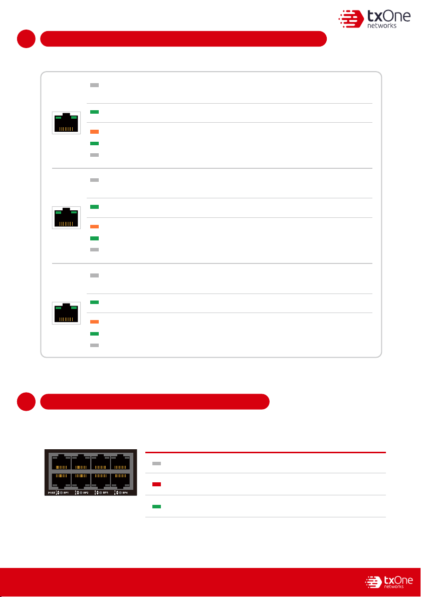
The LED on each Ethernet port shows the deployment status.
Hardware Bypass LED Indicators1
15
1
15
The Bypass LED states and device statuses of each IPS port pair are shown below.
1-2 3-4 5-6 7-8 9-10 11-12BP
1
23
4
PORT 5
67
89
10 11
12
Bypass LED State Device Status
No Light
Hardware bypass pair of ports is enabledTurn on RED
Hardware bypass pair of ports is disabled
No Light The EdgeIPS Pro 216 Rugged appliance cannot communicate with a
network.
MGMT/MR
Right LED 1 Gbps LINK/ACT (on = 1 Gbps link)
Right LED 100 Mbps LINK/ACT (on = 100 Mbps link)
Hardware bypass pair of ports is normalTurn on Green
Right No Light 10 Mbps LINK/ACT (off = 10 Mbps link)
Left LED GE LINK/ACT (off = no link, on = activity)
No Light The EdgeIPS Pro 216 Rugged appliance cannot communicate with a
network.
HA
Left LED GE LINK/ACT (off = no link, on = activity)
No Light The EdgeIPS Pro 216 Rugged appliance cannot communicate with a
network.
RJ45
Left LED GE LINK/ACT (off = no link, on = activity)
Right LED 1 Gbps LINK/ACT (on = 1 Gbps link)
Right LED 100 Mbps LINK/ACT (on = 100 Mbps link)
Right No Light 10 Mbps LINK/ACT (off = 10 Mbps link)
Right LED 1 Gbps LINK/ACT (on = 1 Gbps link)
Right LED 100 Mbps LINK/ACT (on = 100 Mbps link)
Right No Light 10 Mbps LINK/ACT (off = 10 Mbps link)