-8 -
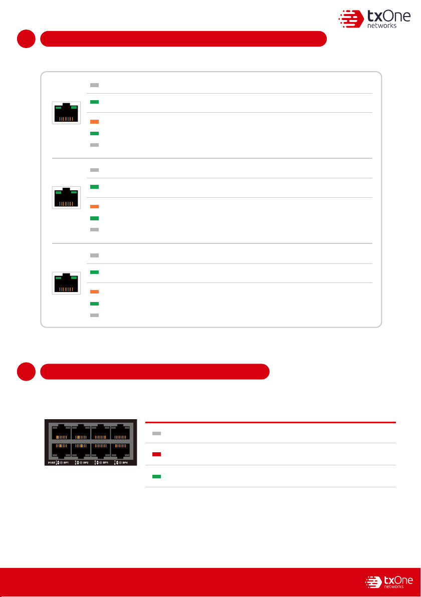
Checking LED Indicators to Confirm Status1
14
The LED on each Ethernet port shows the deployment status.
Hardware Bypass LED Indicators1
15
1
15
The Bypass LED states and device statuses of each IPS port pair are shown below.
1-2 3-4 5-6 7-8 9-10 11-12BP
1
23
4
PORT 5
67
89
10 11
12
Bypass LED State Device Status
No Light
Hardware bypass pair of ports is enabledTurn on RED
Hardware bypass pair of ports is disabled
No Light The EdgeIPS Pro-216 appliance cannot communicate with a network.
MGMT/MR
Right LED 1 Gbps LINK/ACT (on = 1 Gbps link)
Right LED 100 Mbps LINK/ACT (on = 100 Mbps link)
Hardware bypass pair of ports is normalTurn on Green
Right No Light 10 Mbps LINK/ACT (off = 10 Mbps link)
Left LED GE LINK/ACT (off = no link, on = activity)
No Light The EdgeIPS Pro-216 appliance cannot communicate with a network.
HA
Left LED GE LINK/ACT (off = no link, on = activity)
No Light The EdgeIPS Pro-216 appliance cannot communicate with a network.
RJ45
Left LED GE LINK/ACT (off = no link, on = activity)
Right LED 1 Gbps LINK/ACT (on = 1 Gbps link)
Right LED 100 Mbps LINK/ACT (on = 100 Mbps link)
Right No Light 10 Mbps LINK/ACT (off = 10 Mbps link)
Right LED 1 Gbps LINK/ACT (on = 1 Gbps link)
Right LED 100 Mbps LINK/ACT (on = 100 Mbps link)
Right No Light 10 Mbps LINK/ACT (off = 10 Mbps link)