Trevent EL-6-380L User manual
TREVENT EL-6-380L
TREVENT EL-9-380L
TREVENT EL-9-380
TREVENT EL-10,5-380
OPERATION
MANUAL
FOR ELECTRIC FAN HEATERS
TREVENT EL-12-380
TREVENT EL-22,5-380
TREVENT EL-30-380
TREVENT EL-36-380
SAFETY MEASURES
DESIGN AND DIMENSIONS SERVICE
TECHNICAL PARAMETERS
FAN HEATER INSTALLATION

02.
03.
04.
06.
07.
09.
11.
13.
15.
15.
16.
17.
18.
18.
19.
20.
21.
INTRODUCTION
SAFETY MEASURES
CHARACTERISTICS OF ELECTRIC FAN HEATERS SERIES
CONSTRUCTION OF FAN HEATERS
MAIN DIMENSIONS
TECHNICAL DETAILS
AUTOMATICS
POSSIBLE MOUNTING METHODS
CONNECTION OF FAN HEATERS
TREVENT EL-L 6-9 KW
ELECTRIC
FAN HEATERS
OPERATION
MANUAL
REFERENCE INFORMATION
WIRES SECTION CALCULATION TABLE
POTENTIAL PROBLEMS AND
TROUBLESHOOTING METHODS
PASSPORT
WARRANTY
TREVENT EL 9-12 KW
TREVENT EL 22,5-36 KW

02 INTRODUCTION
• This manual is an integral part of the fan heater and must be passed on to the user
together with the fan heater.
• To ensure the correct installation and use of the fan heater, read this manual carefully
before installation.
• We recommend keeping this manual in a safe place so that you can refer to it during
operation.
• We pay special attention to compliance with safety measures when installing this fan
heater, as well as during any actions related to the maintenance service.
• Fan heaters may only be installed and used in the conditions for which they are
intended. Any other use that is not in accordance with this manual may result in property
damage, personal injury or death. Every effort should be made to avoid the possibility of
improper use of the fan heater.
• It is necessary to restrict access to the fan heater by unauthorized persons, as well as to
train the maintenance personnel.
• The manufacturer is not liable for damage caused by the actions of persons unfamiliar
with this manual.
• The manufacturer reserves the right to make changes to this manual without notice.
• The manufacturer reserves the right to make changes to the component parts and
design of fan heaters that do not affect their operation and basic technical parameters.
INTRODUCTION
TREVENT UKRAINE THANKS YOU FOR CHOOSING
TREVENT WATER FAN HEATER.

SAFETY MEASURES
Before carrying out any work related to the maintenance of fan heater, read
the following safety information.
SAFETY MEASURES 03
Foreign objects and liquids must not get inside the fan heater.
Before connecting the power supply source, check if the electrical
network parameters comply with the parameters for which the fan
heater is designed.
The electrical network that powers the fan heater and automatics
must be additionally protected from the phase loss.
Install the fan heater on a solid base that can sustain the weight of the
fan heater.
Check for grounding. Do not use the fan heater without grounding as
this may result in property damage, personal injury or death.
It is not allowed to use the fan heater with fully closed blinds.
The electrical network that powers the fan heater and automatics
must be short-circuit-proof.
Fan heater must be installed and connected to the utility networks
only by qualified personnel with the appropriate access and permits.
Observe all safety rules and regulations when installing, activating,
repairing, and servicing the fan heater.
The principle of operation of the TREVENT fan heaters is based on heating the air that
passes through the electric heater tubes (EHTs) of the fan heater through the use of a fan.
The TREVENT fan heaters are used for heating medium and large-scale facilities, such as
industrial shops, workshops, car showrooms, car washes, warehouses, pavilions, sports
facilities, and so on.
The TREVENT fan heaters are designed for indoor installation and operation in
recirculated air.
04 CHARACTERISTICS OF ELECTRIC FAN HEATERS SERIES
CHARACTERISTICS OF
ELECTRIC FAN HEATERS SERIES
The TREVENT EL-L series includes the fan heaters with smooth EHTs and directional
louvers for optimal warm air flow.
The TREVENT EL-L series includes the following:
• TREVENT EL-6-380L – fan heater with a rated thermal power of 6kW and line supply
of 220V.
• TREVENT EL-9-380L – fan heater with a rated thermal power of 9kW and line supply
of 380V.
Fan heaters have three stages of heating and a control panel with a TREVENT 6-9 L digital
thermostat. After stopping the heating, the fan continues to run for several minutes to
cool the EHTs.
The control panel is powered by a fan heater and is protected against short circuits by
the automatic circuit-breaker in the heater body.
The fan heater is protected from overheating by two self-healing thermal fuses that
temporarily turn off the EHTs when the body overheats, and a thermal fuse with manual
recovery that is activated at a much higher temperature and turns off the EHTs in an
emergency situation.
TREVENT EL-L SERIES
The TREVENT-EL series includes the fan heaters with ribbed EHTs and directional louvers
for optimal warm air flow.
The TREVENT-EL series includes the following:
• TREVENT EL-9-380 – fan heater with a rated thermal power of 9kW and line supply
of 380V;
• TREVENT EL-10,5-380 – fan heater with a rated thermal power of 10,5kW and line
supply of 380V;
TREVENT-EL SERIES
05
• TREVENT EL-12-380 – fan heater with a rated thermal power of 12kW and line supply
of 380V;
• TREVENT EL-22,5-380 – fan heater with a rated thermal power of 22,5kW and line
supply of 380V;
• TREVENT EL-30-380 – fan heater with a rated thermal power of 30kW line supply of
380V;
• TREVENT EL-36-380 – fan heater with a rated thermal power of 36kW line supply of
380V.
Fan heaters have two groups of EHTs and three stages of heating (except for models
with the power of 9kW and 12kW that have two stages of heating). Fan heaters are
equipped with control panels with built-in digital thermostats of ECONOM series for the
TREVENT EL fan heaters with the power of 9–12kW and the TREVENT EL fan heaters with
the power of 22,5-36kW, as well as EL series panels for the TREVENT EL fan heaters with
the power of 22,5-30kW and the PROG series panels for the TREVENT EL fan heaters.
Fan heaters are protected from overheating by two self-healing thermal fuses that
temporarily turn off the EHTs when the body overheats, and a thermal fuse with manual
recovery that is activated at a much higher temperature and turns off the EHTs in an
emergency situation.
After stopping the heating, the fan continues to run for several minutes to cool the EHTs.
In the TREVENT EL models with the power of 22,5-36kW, a ring bolt is provided for safe
lifting of the fan heater to a height.
ХАРАКТЕРИСТИКА СЕРІЙ ТЕПЛОВЕНТИЛЯТОРІВ

TREVENT ELECTRIC FAN HEATER
CONSISTS OF SEVERAL KEY PARTS
DIRECTIONAL LOUVERS with individual adjustment
provide the direction of a warm air stream. Directional louvers
have an aerodynamic profile that allows to receive low coefficient
of air flow resistance and, as a result, the maximum range of warm
air stream.
HEATING ELEMENTS (EHTS) installed in the TREVENT fan
heaters are made of copper and aluminum. For better heat pickup,
ribs that are spirally mounted on EHTs (width of a spiral is 8 mm)
were added to the heating elements. The frame for attaching EHTs
is made of galvanized steel.
Temperature sensors for protection of EHTs from overheating are
mounted in the upper and lower parts of groups of EHTs.
BODY consists of metal elements coated with highly resistant
polymer paint, galvanized fastening and structural elements.
FAN is located in a special diffuser in the rear part of the fan
heater so that the air flow is evenly distributed over the entire
surface of EHTs ensuring their most efficient use. This solution also
reduces the noise level created by the air. The fan is equipped with
a special small intake grille that protects the fan heater from
foreign objects and prevents possible injury to personnel by the
fan blades. Fan protection level IP 54 (EN 60529), insulation class F.
06 CONSTRUCTION OF FAN HEATERS

MAIN DIMENSIONS 07
MAIN DIMENSIONS
TREVENT EL-6-380L / EL-9-380L
TREVENT EL-9-380 / EL-10,5-380 / EL-12-380
480
475
380
478
475
333
458
Ø 10
2 ports
100
Ø 11

08 MAIN DIMENSIONS
MAIN DIMENSIONS
TREVENT EL-22,5-380 / 30-380 / 36-380
730
735
535
707
730
475
745
Ø 11
3 ports
115115
Ø 11
BRACKET MOUNTING DISTANCE. For ease and safety of installation, the ring
bolt must be screwed into the bracket of the fan heater and used for lifting and
securing during installation. Permissible load on the ring bolt according to
GOST 4751-73. When lifting the fan heater, do not deviate from the lifting plane
by more than 45°!

TECHNICAL DETAILS 09
TECHNICAL DETAILS TREVENT EL-L
Model range
Power supply voltage
Power-line frequency
Capacity at heating stages
Rated air capacity
Current
Increase in air temperature
at rated power
Connection wires section
Weight
Main dimensions (LxWxH)
V
Hz
kW
m³/h
А
°С
mm²
kg
mm
EL-6-380L
380
50
2,0
4,0
6,0
1200
3*9
13
5*2,5
17,6
480*380*475
EL-9-380L
380
50
3,0
6,0
9,0
1800
3*13,5
20
5*4
22,5
480*380*475
І
ІІ
ІІІ
TECHNICAL DETAILS TREVENT EL
Model range
Power supply voltage
Power-line frequency
Capacity at heating stages
Rated air capacity
Current
Increase in air temperature
at rated power
Connection wires section
Weight
Main dimensions (LxWxH)
V
Hz
kW
m³/h
А
°С
mm²
kg
mm
EL-9-380
380
50
4,5
9,0
-
1600
3*13,5
18
5*2,5
19
EL-10,5-380
380
50
4,5
6
10,5
1600
3*16
20
5*4,0
19
І
ІІ
ІІІ
EL-12-380
380
50
6
12
-
2500
3*18,5
15
5*4,0
19
EL-22,5-380
380
50
7,5
15
22,5
7000
3*34
19
5*6,0
53,5
EL-30-380
380
50
10
20
30
7000
3*45
16
5*10,0
53,5
EL-36-380
380
50
12
24
36
7000
3*54
22
5*16,0
53,5
730*535*735480*380*475 480*400*475

10 TECHNICAL DETAILS
Δt OF AIR FLOW
Т1 ˚C – air temperature at fan heater inlet.
Т2 ˚C – air temperature at fan heater outlet.
Model Р, kW Т1 ˚C
6
9
9
10,5
0
5
10
15
20
0
5
10
15
20
0
5
10
15
20
0
5
10
15
20
Т2 ˚C
13
18
23
28
33
20
25
30
35
40
18
23
28
33
38
20
25
30
35
45
TREVENT EL-6-380L
TREVENT EL-9-380L
TREVENT EL-9-380
TREVENT EL-10.5-380
Model Р, kW Т1 ˚C
12
22,5
30
36
0
5
10
15
20
0
5
10
15
20
0
5
10
15
20
0
5
10
15
20
Т2 ˚C
14
19
24
29
34
15
20
25
30
35
18
23
28
33
38
21
26
31
36
41
TREVENT EL-12-380
TREVENT EL-22,5-380
TREVENT EL-30-380
TREVENT EL-36-380
•double overheating protection;
•EHTs continue to be aired for some time after switching off;
•two or three stages of heating;
•capability of operation in the fan mode;
•design of fan heater also provides wall mounting;
•thermostat allows to select the desired temperature.
FEATURES OF FAN HEATERS
AUTOMATICS 11
Fan heaters have two groups of EHTs and three stages of heating (except for models with
the power of 9kW and 12kW that have two stages of heating). Control panels with built-in
digital thermostats of ECONOM series for the TREVENT EL fan heaters with the power of
9–12kW and the TREVENT EL fan heaters with the power of 22,5-36kW. As well as EL series
panels for the TREVENT EL fan heaters with the power of 22,5-30kW and the PROG panels
for the TREVENT EL 22,5 fan heaters with the power of 30kW.
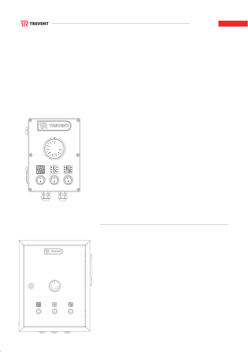
AUTOMATICS
CONTROL PANEL WITH MECHANICAL
THERMOSTAT FOR TREVENT EL-L SERIES
with the power of 6 and 9kW
Designed to control the fan heater for the purpose of
maintaining the set temperature indoors. It is possible
to set the required temperature and operating mode
during working and non-working hours, according to
the weekly schedule, in the scheme of programmable
thermostat during connection. Control panel controls
the operation of two groups of EHTs, which allows to
provide three stages of heating power.
Power supply – 230V/50Hz
Environmental parameters +5…+25°C.
CONTROL PANEL WITH MECHANICAL
THERMOSTAT FOR TREVENT ЕL ECONOM
with the power of 9-12kW and 22,5-36kW
Designed to control the fan heater for the purpose of
maintaining the set temperature indoors. It is possible
to set the required temperature and operating mode
during working and non-working hours, according to
the weekly schedule, in the scheme of programmable
thermostat during connection. Control panel controls
the operation of two groups of EHTs, which allows to
provide two or three stages of heating power.
Power supply – 230V/50Hz
Environmental parameters +5…+25°C.

12 AUTOMATICS
CONTROL PANEL WITH MECHANICAL
THERMOSTAT TREVENT EL AND TREVENT
PROG for the power of 22,5-36 kW
Designed to control the fan heater for the purpose of
maintaining the set temperature indoors. It is possible
to set the required temperature and operating mode
during working and non-working hours, according to
the weekly schedule, in the scheme of programmable
thermostat during connection. Control panel controls
the operation of two groups of EHTs, which allows to
provide three stages of heating power.
Power supply – 230V/50Hz
Environmental parameters +5…+25°C.
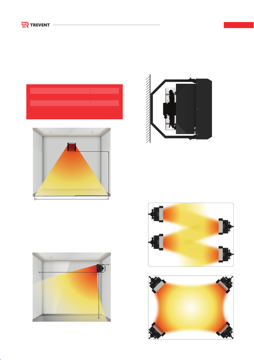
POSSIBLE MOUNTING METHODS 13
POSSIBLE MOUNTING METHODS
TREVENT 6L AND 9L/9/10,5/12 380
WALL MOUNTING
Distance from the wall not less than
Mounting height
Range of air stream
from 0,25 m
2,5-5 m
to 15 m*
* For model with the power of 12kW.
** Directional louvers are installed horizontally.
Recommended distances from the wall and
placement of several fan heaters.
min 0,25m
min 0,5m
2,5-5 m
RECOMMENDED
DISTANCE FROM
WALLS AND CEILING
LACEMENT
OF SEVERAL
DEVICES
5 m
15* m

14 POSSIBLE MOUNTING METHODS
POSSIBLE WAYS OF MOUNTING
TREVENT EL 22,5-36 380
WALL MOUNTING
Distance from the wall not less than
Mounting height
Range of air stream
from 0,25 m
3-8 m
to 25 m
* Directional louvers are installed horizontally.
Failure to observe the minimum distance of
0.25 m from the wall or ceiling will lead to
improper operation of the fan heater, which will
reduce the service life of the fan heater.
min 0,25m
min 0,5m
3-8 m
RECOMMENDED
DISTANCE FROM
WALLS AND CEILING
LACEMENT
OF SEVERAL
DEVICES
3-8 m
25 m
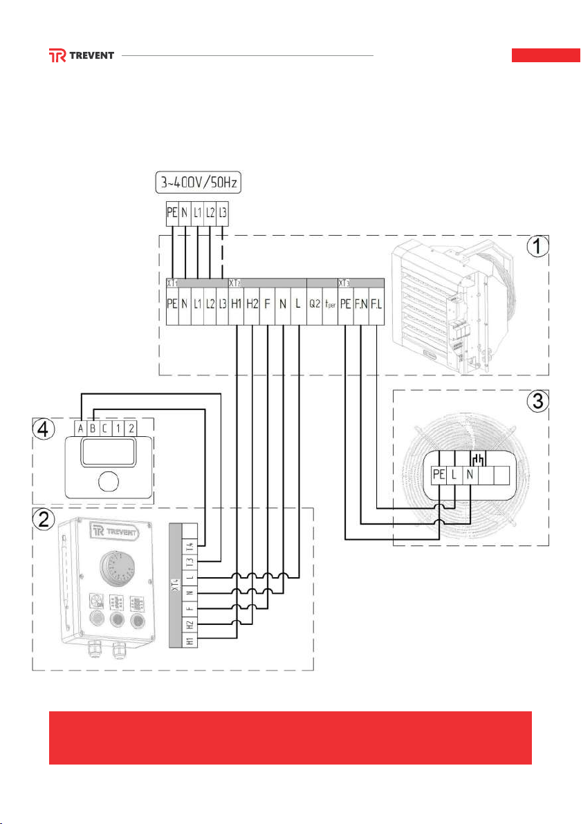
CONNECTION OF FAN HEATERS 15
CONNECTION OF FAN HEATERS
TREVENT EL-6-9-380L
1. EHTS OF FAN HEATER
2. CONTROL PANEL
3. FAN MOTOR
4. THERMOSTAT

16 CONNECTION OF FAN HEATERS
CONNECTION OF FAN HEATERS
TREVENT EL-L 9-12 KW
1. EHTS OF FAN HEATER
2. CONTROL PANEL
3. FAN MOTOR
4. THERMOSTAT
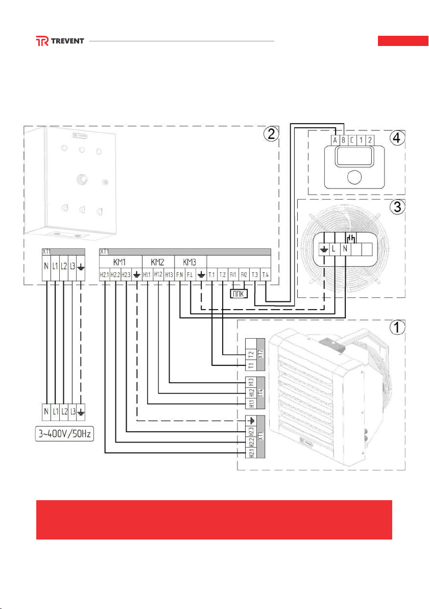
CONNECTION OF FAN HEATERS 17
CONNECTION OF FAN HEATERS
TREVENT EL-L 22,5-36 KW
1. EHTS OF FAN HEATER
2. CONTROL PANEL
3. FAN MOTOR
4. THERMOSTAT

WIRES SECTION CALCULATION TABLE
Section
of power core,
mm² Current, A Power, kW
1,5
2,5
4
6
10
16
25
35
50
70
95
120
19
27
38
46
70
85
115
135
175
215
260
300
4,1
5,9
8,3
10,1
15,4
18,7
25,3
29,7
38,5
47,3
57,2
66,0
16
25
30
40
50
75
90
115
145
180
220
260
10,5
16,5
19,8
26,4
33,0
49,5
59,4
75,9
95,7
118,8
145,2
171,6
Current, A Power, kW
Voltage, 220V Voltage, 380V
Conductor material - copper
Section
of power core,
mm² Current, A Power, kW
2,5
4
6
10
16
25
35
50
70
95
120
20
28
36
50
60
85
100
135
165
200
230
4,4
6,1
7,9
11,0
13,2
18,7
22,0
29,7
36,3
44,0
50,6
19
23
30
39
55
70
85
110
140
170
200
11,6
15,1
19,8
25,7
36,3
46,2
56,1
72,6
92,4
112,2
132,0
Current, A Power, kW
Voltage, 220V Voltage, 380V
Conductor material - aluminum
REFERENCE INFORMATION 18

POTENTIAL PROBLEMS AND
TROUBLESHOOTING METHODS
Problem Possible reason
Fan does not work
Contact a specialized installation
company.
Resolution
Damaged power cord.
Mechanical stop of the fan. Conduct a visual examination.
Remove the foreign object.
Fan works, but the fan
heater does not heat
the air
Find the damaged place,
and repair / replace the wire.
Damaged EHTs power supply wire.
The thermal fuse built in a heater went off. Contact a specialized installation
company.
No power is supplied to
the control panel
Contact a specialized installation
company.
A foreign object fell into the fan blading.
The automatic circuit-breaker built in the
heater went off.
Restore the automatic circuit-breaker
and find out the cause
of its activation.
During operation,
the fan heater makes
unwanted sounds
Conduct a visual examination.
Remove the foreign object.
A foreign object fell into the fan blading.
Non-compliance with installation
recommendations.
Contact a specialized installation
company.
19 REFERENCE INFORMATION
This manual suits for next models
7
Table of contents


