TREX RainEscape User manual

INSTALLATION GUIDE
DECK DRAINAGE SYSTEM
CREATE A
DRY SPACE
below your deck

WATER IS DIRECTED AWAY
FROM YOUR DECK AND INTO
A WATER DRAINAGE SYSTEM
Protect the space below your deck
FROM RAIN, SUN & OTHER ELEMENTS
EXPAND YOUR
OUTDOOR LIVING SPACE

1
This installation guide provides step-by-step instructions on how to install Trex RainEscape
on an elevated deck. Please read through these instructions carefully. For additional information
on how to install Trex RainEscape, please view our videos on the Trex RainEscape
YouTube channel or call a Trex RainEscape Specialist at 1-877-348-1385.
INSTALLATION GUIDE
DECK DRAINAGE SYSTEM

CONTENTS
2
BASIC INSTALLATION
Parts .............................................................................................................................................................. 4
Tools .............................................................................................................................................................. 4
Preparation ................................................................................................................................................... 5
Installing the Trex RainEscape Downspout ................................................................................................ 5
Types of Flashing .......................................................................................................................................... 6
Installing the Trex RainEscape Trough ........................................................................................................ 7
Tape all Seams ............................................................................................................................................. 9
Wall Flash ...................................................................................................................................................... 9
Installing Fascia........................................................................................................................................... 10
Installation of a Gutter System ................................................................................................................. 10
Installing Trex Rainescape Sot Lights...................................................................................................... 11
MODIFICATIONS & SPECIAL CASES
Single Picture Frame or Breaker Board .....................................................................................................14
Double or Triple Picture Frame ..................................................................................................................14
Cantilevered Downspout ........................................................................................................................... 15
Obstructions & Posts ................................................................................................................................. 16
Using the Trex RainEscape Post Flash ...................................................................................................... 16
Surface Post Mount.................................................................................................................................... 17
Installation of a Trough Over a Double or Triple Beam ............................................................................ 17
Modifying Downspouts for Obstructions ................................................................................................. 17
Cutting Around Downspouts and Obstructions ...................................................................................... 18
Double Extended Decks (over 19')............................................................................................................. 18
Installing Can Lighting ............................................................................................................................... 19
Installing Over Deck Steps ......................................................................................................................... 19
INSTALLATION OVER A STEEL JOIST SYSTEM.................................................................... 20
WARRANTY .......................................................................................................................................... 22
FREQUENTLY ASKED QUESTIONS ........................................................................................... 23
*Refer to installation sheet for most current updates
TREX®RAINESCAPE®INSTALLATION GUIDE

HELPFUL TIPS
3
DO'S
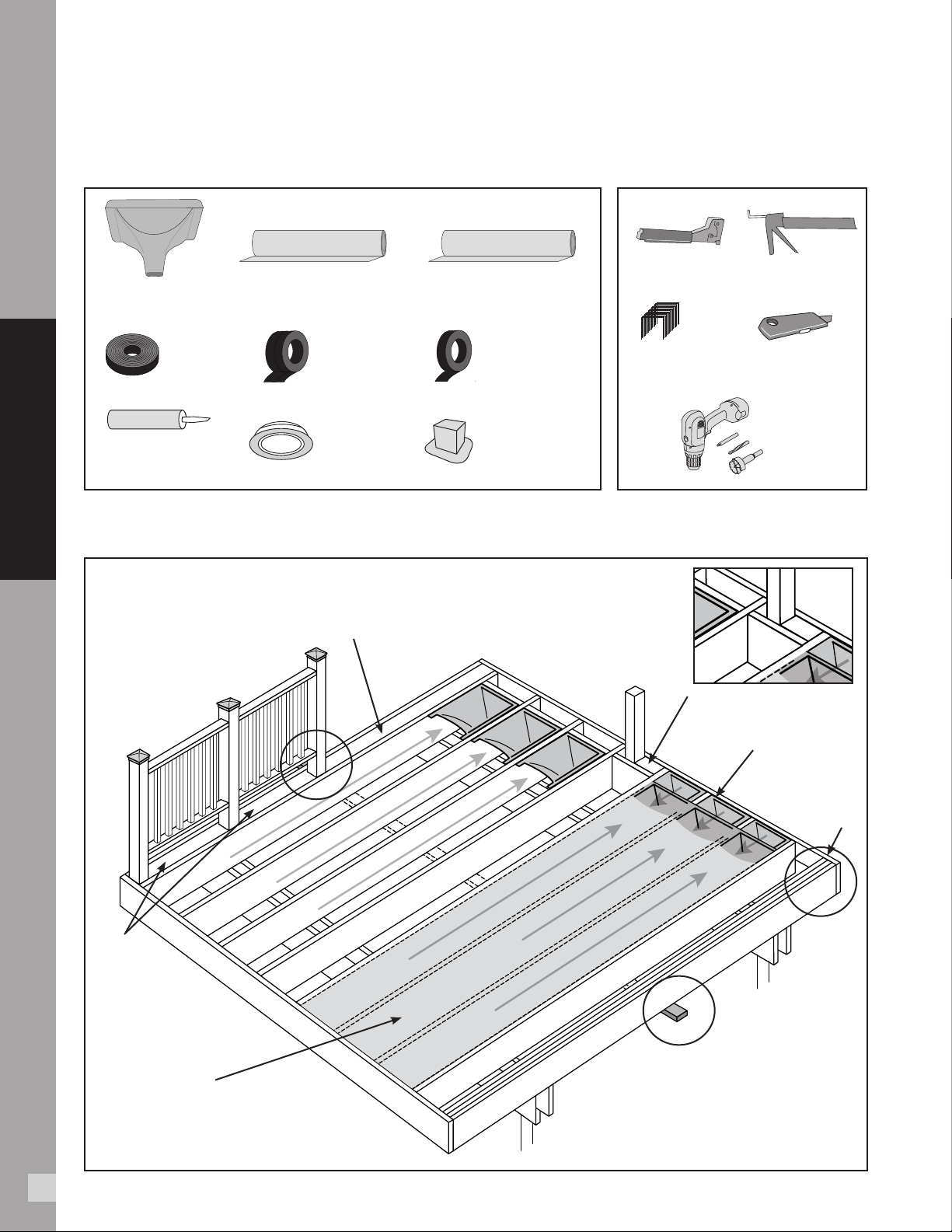
Make all joists straight and square.
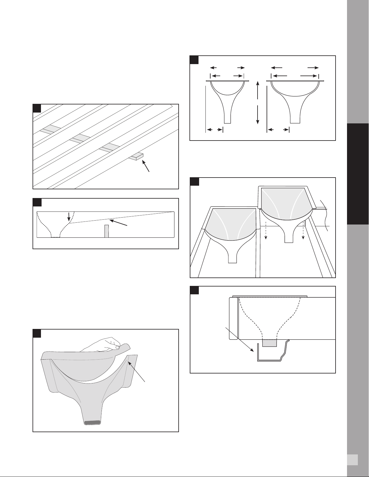
Add outlets to gutter every 12' - 14'.
Cover all joists and blocking with
trough material, then butyl tape.
Cover the Trex RainEscape
system with deck boards.
Ensure the troughs and
downspouts are dry and clear
of debris before applying tape.
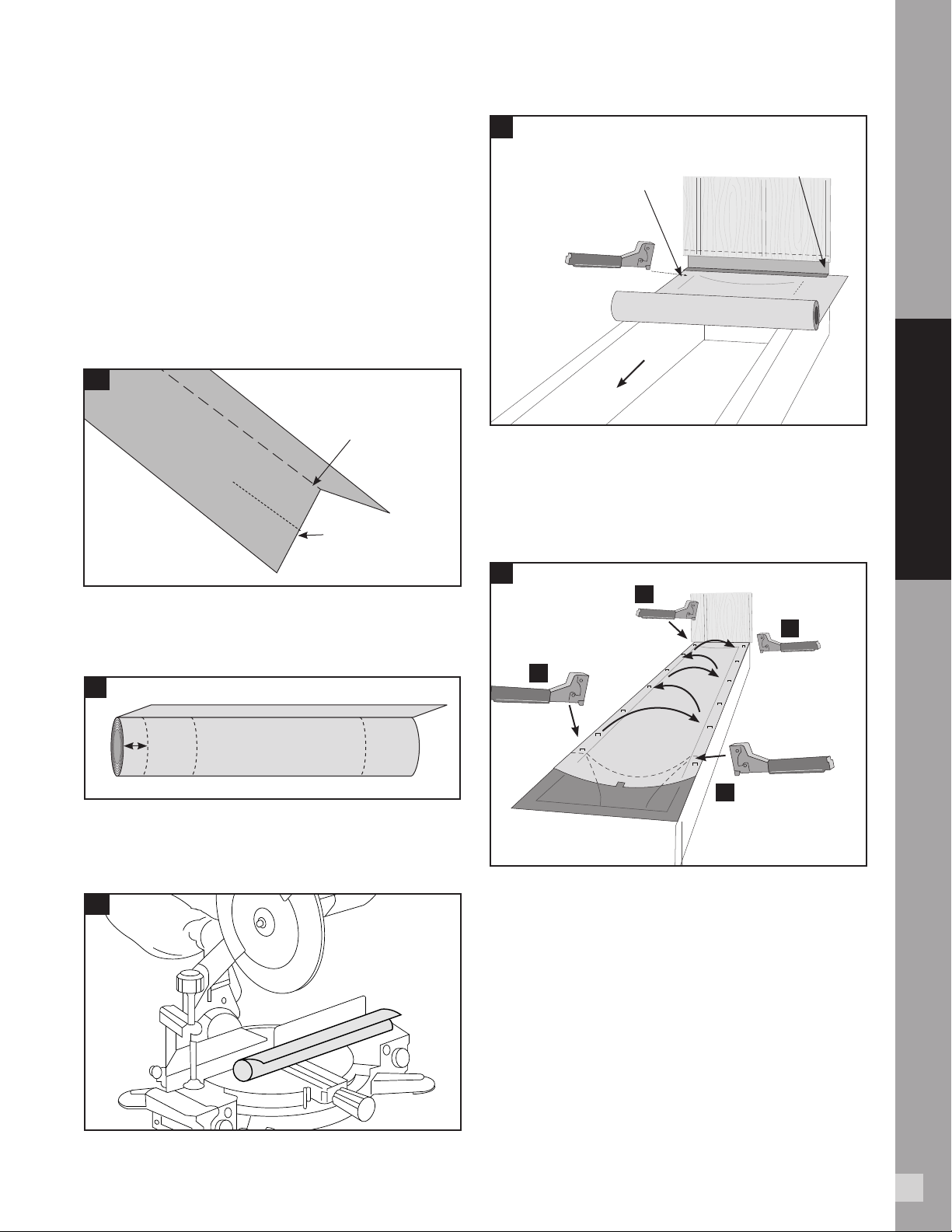
Acclimate the trough
before installing.
Install the trough material
with the shiny side up. Only use
Trex RainEscape branded products.
Scan this QR code to view a video on design
and layout considerations to keep in mind
when installing the Trex RainEscape system.
Always consult with the local building code ocial prior to installing the
system to ensure you are meeting all code and safety requirements.
Trex is not responsible for improper or non-recommended installations.
DON'TS
Do not staple Trex RainEscape products
anywhere other than into or over floor joists,
ledger, rim joists, or headers.
Do not use spiked hidden fasteners, or any
fastener without a flat base to provide pressure
to butyl tape. Call a Trex RainEscape Specialist
at 1-877-348-1385 for recommendations.
Do not over drive double thread screws.
Do not stand anywhere other than the top of
the floor joists, ledger, rim joists, or headers.
The Trex RainEscape system can not support
body weight.
Do not use nails to attach the deck boards
above the Trex RainEscape system.
BEFORE YOU BEGIN
HELPFUL TIPS
THE TREX RAINESCAPE SYSTEM IS MORE EASILY
INSTALLED WITH TWO PEOPLE WORKING TOGETHER
SNOW BUILD-UP
Snow will sit on decking until it melts and then it will run through the system.
LEAVES
If leaves and debris accumulate in the troughs, a standard washing or a hard rain
will clean out the system.
IF THE TAPE WILL NOT STICK
In areas, such as the perimeter, brick or stucco, where the Trex RainEscape tape will
not stick, use the Trex RainEscape butyl caulk to adhere the material.
CAUTION
Do not splice trough material. If the trough material is spliced it must be replaced.
To estimate your materials needs or for questions, visit our website
trexrainescape.com or contact us at 1-877-348-1385

4
PARTS TOOLS
DOWNSPOUT - 40mil
4X4 POST FLASH
(102 mm x 102 mm)
SOFFIT
LIGHT
WALL FLASH
1/4" x 1" x 25'
(6.35 mm x 25.4
mm x 7.62 M)
TROUGH - 20mil
19-5/8" x 16' (49.8 cm x 4.8 M)
TROUGH - 20mil
19-5/8" x 12' 49.8 cm x 3.6 M)
TREX RAINESCAPE BUTYL
CAULK* (10.5 oz tube)
TAPE
4" x 50'
(102mm x 15.24 M)
STAPLE GUN
REGULAR STAPLES
(3/8" or longer)
CAULK GUN
UTILITY KNIFE
WATER FLOW DIRECTION:
1/4" fall per foot
INSTALL
DOWNSPOUTS
(See pg. 5)
INSIDE POSTINSIDE POST
MOUNTMOUNT
2 x 4 FLAT
BLOCK
2 x 4 FLAT
BLOCK
TRIPLE BEAM & FLUSH
MOUNT POST
(See pg. 17)
CANTILEVERED
DOUBLE SIDED TAPE
21/2" x 50'
(63.5 mm x 15.24 M)
BASIC INSTALLATION
FRAMING DETAIL
*One tube covers 25
linear ft. w/1/4" bead
INSTALLATION OF THE
FLAT BLOCKING AND RAILING
(See pgs. 16 & 17)
INSTALLATION
OF THE
TROUGH
(See pg. 7)
PLACE A TEMPORARY
NAILER ATTACHING TO
EACH JOIST
4-5/8" (120 mm)
HOLE SAW
BASIC INSTALLATION

5
1. PREPARATION
»Read all instructions completely before beginning.
»
Place midspan nailer (1) or vertical blocking (1A)
to keep joist straight and prevent rolling.
»
Midspan nailer can be removed when sot or
ceiling is installed.
PLACE A TEMPORARY
NAILER UNDER JOIST
2. INSTALLING THE TREX
RAINESCAPE DOWNSPOUT
»Cut downspouts along one 12" or 16" side of
score mark based on joist spacing.
»Install all downspouts along rim joist and/or
ledger board. Cut-out side should face open
deck bay. DOWNSPOUT
SHOULD EXTEND
ABOUT 1" INTO
THE GUTTER
SIDE VIEW
TEAR OUT OPENING
AS MARKED ON THE
DOWNSPOUT. (IN
COOLER WEATHER USE
A UTILITY KNIFE)
»
Downspout should extend 1" into gutter: cut or
extend as necessary. (2C)
1
2
2A
2B
2C
1A
MAXIMUM DEPTH FOR TROUGH IS 4"
4"
SIDE VIEW
BLOCKING
BLOCK BELOW THE
TROUGH SYSTEM
16" CENTER12" CENTER
10-1/4"
4" 5-1/4"
14-1/2"
10"
BASIC INSTALLATION

8
3. THREE TYPES OF FLASHING:
With Flashing
»When using flashing add a bead of butyl caulk at the
ledger board and between the flashing and trough.
Tape over the flashing to the top of the trough
using the 4" RainEscape butyl tape. (3A)
Flashing with Brick or Stucco
»Cut into mortar or cement joint. (3C) Caulk "Z"
flashing into mortar. Install trough under flashing
as shown in (3A). Tape over flashing to the top
of the trough using the 4" RainEscape butyl tape.
CAULK "Z" FLASHING WITH TREX
RAINESCAPE BUTYL CAULK
CUT MORTAR
3B
WHEN USING FLASHING, ADD
A BEAD OF BUTYL CAULK AT
THE LEDGER BOARD AND
UNDER THE FLASHING. TAPE
OVER THE FLASHING TO THE
TOP OF THE TROUGH.
4" BUTYL TAPE
4" BUTYL TAPE
RECOMMENDED
CAULK LEDGER BOARD INTO HOUSE WITH
TREX RAINESCAPE BUTYL CAULK
CAULK TROUGH
INTO HOUSE WITH TREX
RAINESCAPE BUTYL
CAULK
3C
CAULK WITH COLOR MATCH
SILICONE (NOT SUPPLIED) OR
USE TREX WALL FLASHING
3A
6
BASIC INSTALLATION
No Flashing with Brick or Stucco
»If installing against brick or stucco and you
DO NOT need a 100% water tight seal,
use the caulking method. (3C)
Trex does not endorse installing the system without
flashing. If installation with flashing is not possible, refer
to your local building code official for an exception.

9
4. INSTALLING THE TREX RAINESCAPE
TROUGHS
NOTE: If installing when temperatures fluctuate
drastically, be sure to acclimate trough material before
installing. Especially if you are using black. Here are
two ways.
»
Fold a soft crease down the center of the trough.
Be sure to account for the oset if installing for
a 12" joist bay. (4A)
»
Unroll trough material, giving plastic time to relax
and acclimate to outdoor temperatures.
TO EASE INSTALLATION, FOLD A
SOFT CREASE DOWN THE CENTER OF
THE TROUGH BEFORE INSTALLING.
IF INSTALLING IN A 12" JOIST
BAY THE FOLD NEEDS TO BE
OFFSET TO ACCOMMODATE
THE JOIST BAY
1-1/2" 4" CUT LINE
4C
4A
4B
UNROLL USING
11/2" SCORE MARK
ON INSIDE OF
JOIST AS A GUIDE
SLIDE TROUGH UNDER FLASHING
PLACE FIRST STAPLE
ROLL
UNROLL TO THE DOWNSPOUT
SMOOTH/SHINY SIDE FACES UP
4D
»
When working with the Trex RainEscape trough
material, ensure that the smooth/shiny side
always faces up.
»
If installing the system on 12" o.c. joist, cut the 1 -1/2"
score mark side back 4". Then align the left edge of
the trough with the outside of the joist. (4B)
»Hold roll so 1 -
1/2"
score mark is on the left. (4D)
»Line up the 1 -
1/2"
score with the second joist.
»Place first staple at ledger board on 1 -
1/2"
score
mark side. (4E)
1
2
3
4
PLACE 3RD STAPLE THROUGH
TROUGH AND DOWNSPOUT
PLACE FIRST
STAPLE
AT LEDGER
PLACE SECOND
STAPLE BEFORE
DOWNSPOUT
FINISH STAPLING EVERY
8"TO 10"GOING FROM
SIDE-TO-SIDE UNTIL YOU
REACH THE LEDGER
4E
»Unroll trough to downspout using 1 -
1/2"
score
mark on inside joist as guide.
»Cut trough to length to back wall of downspout.
»To remove memory from sheet, backroll the last
few inches of the trough. (4F)
NOTE: If run is longer than 12', put down second staple
halfway down second joist.
7
»
Measure over 4" on the 1-1/2" score mark side and cut
o for 12" on center joists. (4C)
BASIC INSTALLATION

10
8
BACKROLL LAST FEW INCHES
TO REMOVE MEMORY
FROM TROUGH
CUT A 1" WIDE BY 3/4" TAB
TO PREVENT WICKING
AND FOLD
DOWN TAB
CUT OFF EXCESS TROUGH 1"
AWAY FROM THE BACK OF
THE DOWNSPOUT WALL
4F
»Pull trough tight to ensure memory is released,
and place second staple on inside joist
through downspout. (4E)
»On outside joist, form a trough into downspout
while lining up the edge of the score mark with
inside of joist. Place third staple through trough
and downspout on outside joist. (4E)
»Cut a 1" wide by 3/4" tab at center edge of trough
(fold tab down) to prevent wicking. (4F)
»Pull corner at ledger and outside joist tight
keeping entire length of trough smooth and
wrinkle-free so as not to impede water flow. (4E)
»Place fourth staple on outside joist. (4E)
»Continue stapling every 6"to 8"from downspout
to ledger on both joists to secure. (4E)
»Trough material must cover all exposed
wood on surface of deck
SCORE DOWN THE MIDDLE
OF THE TROUGH TO REMOVE
WRINKLES IF NEEDED WITH A
SCREEN SPLINE ROLLER
4H
RUN A WATER TEST
TO ENSURE WATER RUNS
TO DOWNSPOUT
TROUGH WILL PITCH 1/4"
PER 1' OR MORE
4G
NOTE:
In extreme temperature swings, trough material
will expand and contract. Some wrinkling is acceptable but
should not impede the flow of water.
»To test for correct slope, pour a cup of water on
trough at ledger board ensuring water runs to
the downspout. (4G)
»Follow above step for the remaining troughs.
BASIC INSTALLATION

11
TAPE ALL SEAMS ON
THE TROUGHS AND
DOWNSPOUTS
CUT WALL
FLASHING
TO WIDTH
SNAP A CHALK
LINE DOWN THE
CENTER OF THE
JOIST ON TOP OF
TAPE TO ENSURE
PROPER DECK
FASTENING
TRIM EXCESS TROUGH
AT SEAMS, KEEPING OVERLAP
KEEP KNIFE FLAT TO
AVOID SLICING
INTO TROUGH
TRIM EXCESS
(APPROX. 4"BACK)
TAPE
4'
5A
5B
6A
6B
6C
»Using Trex RainEscape tape, tape all seams, joints
and perimeter making sure the flashing is taped to
the trough. (5B)
NOTE:
Tape works off of compression and must be
pinched between decking and joist to make a tight seal.
NOTE:
The butyl tape should never be put directly on the
board without the trough material or a downspout below it.
5. TAPE ALL SEAMS
»Trim excess trough at seams, keeping overlap so
tape will cover the top of the joist and seams. (5A)
6. WALL FLASHING FOAM STRIP
»Cut a piece of the self-adhesive wall flash the
width of the deck. (6A)
»Peel release paper from the wall flashing and
adhere to edge of decking. (6B)
»Push first deck board up against house to
compress wall flash. Then secure decking. (6C)
PUSH AGAINST HOUSE
(TAPE WILL COMPRESS)
TROUGH
FLASHING
WALL FLASH
9
BASIC INSTALLATION

10
ATTACH A STANDARD GUTTER SYSTEM (NOT
INCLUDED) TO COLLECT THE WATER FROM THE
TREX RAINESCAPE DOWNSPOUTS
FRONT VIEW
CUT A TAB ON THE TOP OF
THE GUTTER AND FOLD OVER
ATTACH TO THE BOTTOM
OF THE JOIST
ATTACH A PIECE
OF L-METAL TO
THE GUTTER, THEN
TO THE BOTTOM
OF THE JOIST
ATTACHING THE GUTTERS
8. INSTALLING A GUTTER SYSTEM
(not included)
»Before installing a gutter system perform a water
test to clean out the system and check for any leaks.
»Attach a standard gutter system to collect the
water from the Trex RainEscape downspouts.
DOWNSPOUT SHOULD
EXTEND ABOUT 1"
INTO THE GUTTER
WE SUGGEST INSTALLING A 2x4 or 2x6 ACCESS PANEL TO CHECK GUTTER
WITHOUT REMOVING SOFFIT
SIDE VIEW
NOTE:
Installing a clean-out trim piece will allow access to
gutter line after installation.
8A
7
8B
8D
8C
FOR 2 x 12 JOIST
EXTEND THE
DOWNSPOUT USING
A STANDARD
GUTTER DOWNSPOUT
AND TRIMMED
TO LENGTH
FOR 2 x 6 OR 2 x 8
JOIST, DOWNSPOUT
NOZZLE CAN BE CUT
TO LENGTH
SCREW GUTTER
TO DOWNSPOUT
DECKING
TROUGH
TROUGH
TAPE
TAPE
FASCIA
SOFFIT
SOFFIT
SOFFIT
SOFFIT
7. INSTALLATION OF FASCIA
»Deck board go over fascia. (7)
2 x 4 ACCESS
PANEL
2 x 4 ACCESS
PANEL
SIDE VIEW
BASIC INSTALLATION
BUTYL
CAULK
BUTYL
CAULK
BUTYL
CAULK
BUTYL
CAULK

13
SOFFIT LIGHT
9A
LIGHTING LAYOUT
TOOLS NEEDED
9. INSTALLING TREX RAINESCAPE SOFFIT LIGHTS
»
Space lights every 6' (1.82 m) or to desired span.
GENERAL INFORMATION
»
ALWAYS consult local codes before beginning a project.
»
USE TREX TRANSFORMER ONLY.
Use of any other transformer voids warranty.
»Lights must be installed in a dry area.
»Allow light to cool before removing.
»
The light requires an unobstructed cooling zone
around and above the light. Under no circumstance
is this 2" zone to be reduced either through
insulation or construction materials.
PLANNING
NOTE: When designing your deck, plan locations of lights,
power supply, timer, and dimmer. These should be accessible
for service. Installing a GFCI outlet is REQUIRED to help
prevent damage to lighting from electrical surges. (9A)
1. The dimmer remote will work in a 30' (9.1 m)
radius of the unit.
2. Dimmer should be installed in a dry location.
3. Timer must be installed vertically with receptacle
facing downwards. Timer must be at least 1' (.30
m) from ground level when installed as per federal
safety code height regulations. Timer must be in
view of the sun to use the dusk/dawn feature.
NOTE:
For installations where the transformer is hardwired
to an AC switch, please consult a licensed electrician.
MEASURING
1. Measure joist length and divide by 5.
2. Measure deck width and divide by 5.
3. Take the answer from #1 and multiply by the
answer of #2 = the total number of lights. (9B)
NOTE: It is better to over light your area. A dimmer
switch can be added later to soften the lighting.
2
2
3
1
6"
(15.2 cm)
Post
Post
Sleeve
1
2
1
2
GFCI
Outlet
Timer
TREX Transformer
To Splitter
Dimmer
(Optional)
6"
(15.2 cm)
1
2
Light
connection Connection
wire
Connection wire
TRANSFORMER CAPACITY BY TYPE
8.3A Transformer
(83 DL TRANSFORMER)
Type of Light
2.5A Transformer
(25 DL TRANSFORMER)
Sot Light
23
7
Above listing is for maximum number of each individual light. If mixing and matching
lighting, contact Trex to determine if more than one transformer is required.
INSTALLING WIRING
NOTE: It is recommended to install wiring and
splitters before decking and railing is installed.
»Use male-to-male connection wire (lengths vary)
that will connect to each required splitter.
1. Wiring must be run through deck joist at desired
location. DO NOT run wires between deck boards
and joists. Staple to frame with cable staples at
least 1/4" (0.6 cm) wide. DO NOT crush wire
insulation with staple.
GFCI
Outlet
TREX
Transformer
4-5/8" (120 mm)
HOLE SAW
JIG SAWHAMMERCAULK GUN
SPLITTER
LIGHT
11
REQUIRED FOR INSTALLATION
Purchase of TREX LED Transformer, TREX
10' Lighting Extension Wire, and TREX Transformer
6-way Splitter for operation. All sold separately.

14
SOFFIT LIGHT
MAKING CONNECTIONS
1. Install splitters to inside of framing using hardware
provided. Install a splitter at every junction where
you will run a row of lights. (9E)
2. Run wire through joist and roll up 1' - 2' (0.30 m -
0.60 m) extra wire in area the light will be installed.
Staple to the side of the joist (making sure
not to staple through the wire).
3.
Cap o all unused female connections on splitters
using caps provided or weather resistant silicone. (9G)
EXAMPLE OF A 2 ROW LIGHT INSTALLATION
FOR JOISTS BETWEEN 9' AND 12' (2.76 - 3.65 M)
EXAMPLE OF A 1 ROW LIGHT INSTALLATION
FOR JOISTS LESS THAN 8'
EXAMPLE OF A 3 ROW LIGHT INSTALLATION
FOR JOISTS BETWEEN 13' AND 16' (3.96 - 4.87 M)
2
2
3
1
6"
(15.2 cm)
Post
Post
Sleeve
1
2
1
2
GFCI
Outlet
Timer
TREX Transformer
To Splitter
Dimmer
(Optional)
6"
(15.2 cm)
1
2
Light
connection Connection
wire
Connection wire
2
2
3
1
6"
(15.2 cm)
Post
Post
Sleeve
1
2
1
2
GFCI
Outlet
Timer
TREX Transformer
To Splitter
Dimmer
(Optional)
6"
(15.2 cm)
1
2
Light
connection Connection
wire
Connection wire
2
2
3
1
6"
(15.2 cm)
Post
Post
Sleeve
1
2
1
2
GFCI
Outlet
Timer
TREX Transformer
To Splitter
Dimmer
(Optional)
6"
(15.2 cm)
1
2
Light
connection Connection
wire
Connection wire
Joist Length
Deck Width
House
9’ - 12’
13’ - 16’
SPLITTER
LIGHT
INSTALLING THE LIGHTS
»Install ceiling of your choice. Make sure to
remember where wire end is located.
»Mark where the light is to be installed and use
4-5/8" or 120 mm hole saw to bore hole,
(a jig saw can be used instead of a hole saw).
»Reach up through the hole and pull out wire end
and attach to light.
» Fold orange springs up and push light into opening.
The springs will fold down and hold light in place.
»If using directional feature, spin light so it
shines on desired area.
9B
9E
9F
9G
9C
9D
ROW 1
ROW 1
ROW 1 ROW 2 ROW 3
ROW 2
12

PICTURE FRAME
(See pg. 14)
CANTILEVERS
(Trex RainEscape can accommodate any angle
or radius – max. of 3') (See pg. 15)
EXTENDED
DECK
(See pg. 18)
DOUBLE OR TRIPLE BEAM
(See pg. 17)
MODIFICATIONS AND SPECIAL CASES
MODIFICATIONS & SPECIAL CASES
13
10A. FLAT BLOCKING, SINGLE PICTURE
FRAME/BREAKER BOARD
»Place a horizontal nailer flush with the top of the
joist from the ledger board to the rim joist.
»Caulk between the blocking and the joists seam.
»Cover nailer with trough, making sure to overlap
adjoining downspout and trough.
»Cover all seams with 4" butyl tape and
anywhere a screw can penetrate.
NOTE:
Do not use larger than 2" x 6" flat blocking.
10B. DOUBLE OR TRIPLE PICTURE FRAME:
2 X 4 SHIMS
»Install the Trex RainEscape system as per
previous instructions. (pp 5-9)
»Tape all joints and seams.
»Screw down 2" x 4" pressure-treated shim blocking
on top of the installed the RainEscape system over
the joists and wherever blocking is needed to
support deck boards.
»Attach decking. (When attaching decking use
fasteners that do not penetrate all the way
through the 2 "x 4" shim).
SINGLE PICTURE FRAME
10A
HORIZONTAL BLOCKING
RUNS THE ENTIRE
LENGTH OF THE JOISTS
TROUGH OVERLAPS
BY AT LEAST 1"
TAPE OVER
SEAMS AND
ANYWHERE
SCREW MAY
PENETRATE
APPLY BUTYL CAULK
BETWEEN THE BLOCKING
AND THE JOISTS SEAM
DOUBLE OR TRIPLE PICTURE FRAME (2 X 4 SHIM)
SCREW DOWN 2 X 4
PRESSURE TREATED
SHIM BLOCKING ON TOP
OF THE INSTALLED DOWN
SPOUT AND TROUGH
DIAGONAL SHIM ON CORNERS
TO ACCEPT DECKING DOWNSPOUTS
TROUGHS
TAPE OVER ALL
JOINTS AND SEAMS
DO NOT USE SCREWS THAT PENETRATE THROUGH THE 2X4 SHIM AND PUNCTURE
HOLES IN THE TROUGH MATERIAL WHERE ITS NOT TAPED OR SEALED
10B

16
MODIFICATIONS & SPECIAL CASES
14
12" O.C.
16" O.C.
4x4 POST FOR RAILING
PUT FLAT BLOCKING TO FILL IN ALL OPEN SPACE TO SUPPORT TROUGH
2x4 BLOCK
DOUBLE OR TRIPLE PICTURE FRAME (LADDER BOX)
2 X 4 LADDER BOX
DOWNSPOUTS DRAIN INTO
COLLECTION GUTTER
DOWNSPOUTS INSTALL IN EACH
LADDER BOX. DO NOT TEAR OUT
OPENING ON DOWNSPOUT
11"BLOCKING
ON ENDS
FLAT BLOCK
FUNNEL IN EACH
COVER BLOCKING WITH
TROUGH AND TAPE
10C
11A
11B
10C. DOUBLE OR TRIPLE PICTURE FRAME:
LADDER BOX
»Place a 11" blocking horizontally on the ends of
the bay to support 45° decking.
»Install a 2 x 4 ladder box to support downspouts.
»Trim o all downspout nozzles to accommodate gutter.
»Place downspouts into ladder box
(DO NOT REMOVE OPENINGS).
»Install a piece of trough material over the 11"
blocking, making sure to overlap downspouts
and the adjoining trough.
»
Tape over blocking, joints and seams making sure that
all screw penetrations go through trough and tape.
11. INSTALLING RAILING USING
THE LADDER BOX METHOD
If installing an inset post with double picture frame
using ladder box method:
»
Decide where each post will need to be attached
»
Use vertical and flat blocking at desired location
as shown. (11A)
»Cover all flat blocking with trough material
and caulk all seams.
»Caulk around all flat blocking. Cover with trough
material and tape all seams.
12A. RAILING POSTS, 6X6 POSTS AND
OBSTRUCTIONS WHEN
NOT
USING
4X4 POST FLASH
»To install a post or obstruction on the inside rim
joist, first mark the edges of the post on the trough
and draw two lines, corner to corner. Cut along the
diagonal lines.
»Pull up tabs and install the post.
»Staple all remaining trough over flat blocking (10A).
»Tape starting at bottom of the trough, up the post
overlapping layers to assure a water tight seal
working up around the post extending down onto
the trough. Cut the tape at a 45-degree angle on all
corners. Place a small piece of tape over the corners
where the trough and post meet, to seal the corners
from any leaks. (12A)
MARK EDGES OF POST ON TROUGH
AND CUT DIAGONAL LINES
FROM CORNER TO CORNER
PULL UP TABS ON ALL FOUR
CORNERS AND INSTALL
THE POST
WRAP TAPE AROUND THE POST EXTENDING
DOWN ONTO THE TROUGH. CUT THE TAPE AT
A 45 DEGREE ANGLE ON ALL CORNERS WHERE
THE TROUGH AND POST MEET TO SEAL THE
CORNERS FROM ANY LEAKS.
12A
FOLLOW "9A" OF THIS INSTALLATION
GUIDE FOR ALL POST INSTALLATIONS

17
12B
12C
15
MODIFICATIONS & SPECIAL CASES
13. USING THE TREX RAINESCAPE
4X4 POST FLASH
»Install the trough as shown in 12A.
»Run a bead of butyl caulk around the post,
no more than 1" above the base of the post.
»Slide the post flash down over the bead of butyl
caulk, and tape the flanges to the top of the trough
and then tape the top of the post flash to the 4x4
post.
»After decking is installed, attach the post sleeve.
»If no post sleeve is used for the final deck, trim the
post flash to the height of the finished deck.
»
NOTE:
Post flash only available for 4 x 4 posts.
See section 12 for other sizes and obstructions.
12B.
RAILING POSTS, 6X6 POSTS & OBSTRUCTIONS
WHEN USING 4X4 POST FLASH
»To install a post or obstruction on the inside rim
joist, first mark the edges of the post on the trough
and draw two lines, corner to corner. Cut along the
diagonal lines. (12A)
»Pull up tabs and install the post.
»Staple remaining trough to cover flat block. (10A)
»Cut the post flash into four even sections. (12B)
»Attach one piece to each corner of the post. (12C)
»Tape starting at bottom of the trough, up the post
overlapping layers to assure a water tight seal
working up around the post extending down onto
the trough. (12A)
13A
13B
13C
13E
13D
POST SLEEVE
BEFORE INSTALLING THE POST FLASHING,
APPLY A BEAD OF BUTYL CAULK 1" ABOVE
THE TROUGH, THEN SLIDE THE POST
FLASHING DOWN
APPLY TAPE TO THE TOP OF THE
TROUGH OVER THE BLOCKING,
OR ANYWHERE THERE MAY BE
A PENETRATION FROM NAILS
OR DECK SCREWS
TOP VIEW SIDE VIEW
APPLY TAPE TO THE FLASHING AND
THE TROUGH MATERIAL
IF USING A POST SLEEVE APPLY TAPE
TO THE FLASHING AND THE POST
IF NOT INSTALLING A POST SLEEVE,
CUT POST FLASHING TO THE TOP
OF THE FINISHED DECK

16
BARRIER STRIPS
MODIFICATIONS & SPECIAL CASES
14. SURFACE MOUNT POST TO SOLID
BEAM OR FLAT BLOCKING
»When using surface mount post, pre-drill holes then
use a small amount of butyl caulk on screw threads
to seal holes.
»DO NOT use too much butyl caulk or it will overflow
on deck and post mount.
NOTE:
Please refer to Trex.com for detailed post
mount instructions.
»Insert the (2) stainless steel barrier strips
under the mounting bolt holes. Barrier strips
are required only if attaching post directly to
pressure treated framing.
»Attach posts using four 3/8" x 6" (1 cm x 15.2
cm) hex cap bolts, washers, and nuts, along with
aluminum back plate on underside of blocking.
14A
14B
CUT 1" OFF THE BACK OF THE DOWNSPOUT
THAT FACES THE CANTILEVER
ATTACH
TROUGHS
ATTACH A SECOND TROUGH
FROM THE BACK OF THE
CANTILEVER AND EXTEND
BEYOND THE EXISTING
DOWNSPOUT
TRIM OFF EXCESS
TROUGH MATERIAL
15. CANTILEVERED DOWNSPOUT
»Tear o the cut-out on the front panel of
the downspout.
»On the back side of the downspout draw a line
from corner to corner extending down 1".
Cut the downspout following the line. (Some
downspouts may have this line pre-indicated).
»Staple the trough material from the end of the
cantilever over the existing trough. Repeat all the
steps as necessary for trough installation.
»Tape over all joists and seams.
15

17
18. MODIFIED DOWNSPOUTS
»
For odd joist spacing you must modify the downspout.
»Tear or cut out the front opening.
»Cut through the back of the downspout half way
down, so that downspout fits bay opening.
»Adjust the downspout to fit in the bay and
staple to secure.
»Finish by taping the seam from top to bottom.
CUT DOWNSPOUT
THROUGH THE BACK
TOP TO BOTTOM
ADJUST SIZE AND STAPLE
TO THE BACK OF THE BAY
IF USING 12 & 16 O.C. FUNNELS,
MAKE SURE TO ALIGN DOWNSPOUTS
TAPE SEAM
TOP TO BOTTOM
18
RUN A BEAD OF BUTYL CAULK
BETWEEN BEAMS
FINISH BY TAPING
OVER ENTIRE BEAM
AND TROUGH TO
ENSURE PROPER
SEALING WHEN
ATTACHING
DECKING
17. INSTALLING A TROUGH OVER
A DOUBLE OR TRIPLE BEAM
»Caulk between each beam to ensure a water tight
seal between the beams.
»
Cover the top of the beam with the trough material
that overlaps into both adjacent bays. Tape seams and
trough material where screw penetration may occur.
»Tape over the top of the triple beam and trough
material that sits on top of the beam.
NOTE:
All wood must be covered with trough material
and taped wherever decking will be screwed.
If installing a post in this location, consult with the local
building code official prior to installation to ensure
all code and safety requirements are met.
17
TROUGH
TROUGH
TROUGH
INSTALL ENOUGH TROUGH
MATERIAL TO COVER THE TRIPLE
BEAM AND EXTEND AT LEAST 2"
INTO THE ADJOINING TROUGHS.
TAPE THE SEAMS OF THE
TROUGH MATERIAL TOGETHER
MODIFICATIONS & SPECIAL CASES
DOWNSPOUT
DOWNSPOUT
SECOND STORY GUTTER DUMPS INTO FUNNEL
TROUGH FLOW
TROUGH FLOW
16A
16B
16. DRAINING SECOND STORY GUTTER
ON DECK
»Block out a 14" x 16" o.c. rectangle where the second
story gutter discharges onto the deck. (16B)
»Place downspout in rectangle (do not
remove openings).
»Tape downspout in place.

18
TROUGH
TROUGH
WIRE
WIRE
SIDE VIEW
DECKING
SIDE VIEW
JOIST JOIST
JOIST JOIST
21B
21A
20. DOUBLE EXTENDED DECKS (OVER 19')
»Place downspouts on the opposite ends from where
the existing deck and the deck extension meet.
»Install a trough from the blocking of the extension
to the downspout.
»
Tape all seams & edges as per previous instructions.
PLACE DOWNSPOUTS ON THE ENDS
PLACE BLOCKING BETWEEN JOIST TO BEST
UTILIZE 12' OR 16' TROUGH MATERIAL
20
21. RUNNING WIRES OR OBSTRUCTIONS
THROUGH TROUGH OR DOWNSPOUT
»
Two ways to run wire through Trex Rainescape system:
#1 PENETRATION THROUGH TROUGH
»Pick bay for penetration. Poke hole large enough
for wire.
»Mark near joist where wire will penetrate. Keeping it
close to joist helps with connection point and hole is
at highest point of trough. (21A)
CUT OUT THE END OF DOWNSPOUT
AROUND THE POST
SLIDE A SCRAP PIECE OF TROUGH
MATERIAL OVER THE CUT-OUT
TAPE AROUND POST
AND PATCH AREA
CREATE TABS
ON THE PATCH
19. MODIFYING DOWNSPOUT
FOR OBSTRUCTIONS
»Trace the obstruction on the downspout and
remove the material with a knife. (19A)
»Cut a patch of trough material 2" larger than the
opening and create flaps on patch as per previous
instructions (obstructions and posts) and slide over
the top of the obstruction. (19B)
»Tape over trough material, using caulk if
necessary. (19C)
19A
19B
19C
MODIFICATIONS & SPECIAL CASES
Table of contents
Other TREX Lawn And Garden Equipment manuals
Popular Lawn And Garden Equipment manuals by other brands

Everbloom
Everbloom E281719 installation guide

MK Diamond Products
MK Diamond Products MK SG-2 Owners and operation manual

Simplicity
Simplicity 1691788 Operator's manual

Craftsman
Craftsman 842.242560 owner's manual

Mosquito Magnet
Mosquito Magnet PATRIOT PLUS Operation manual

Poulan Pro
Poulan Pro 967027201 user manual