Tri-Clover Tri-Flo CL Series User manual

Tri-Flo CL Series
Centrifugal Pumps
®
Service & Installation Manual
CLSM-98a

- 2 -
CONTENTS
Thank you for purchasing a Tri-Clover Product!
This manual contains disassembly and assembly instructions, maintenance procedures,
troubleshooting, and a complete parts list for all CL Series Centrifugal Pumps designed and
manufactured by Tri-Clover Inc., Kenosha, Wisconsin.
READ THIS MANUAL
carefully to learn how to service these pumps. Failure to do so could
result in personal injury or equipment damage.
SAFETY
DO'S AND DON'TS ........................................................................................................................... 3
IMPORTANT SAFETY INFORMATION ............................................................................................ 4
TECHNICAL INFORMATION
TECHNICAL DATA ............................................................................................................................ 5
INSTALLATION
UNPACKING EQUIPMENT............................................................................................................... 6
INSTALLATION ................................................................................................................................. 7
OPERATIONAL CHECK ................................................................................................................... 8
MAINTENANCE
CLEANING AND REPAIR ................................................................................................................. 9
MAINTENANCE
DISASSEMBLY ................................................................................................................................. 10
INSPECTION .................................................................................................................................... 15
ASSEMBLY ....................................................................................................................................... 15
TROUBLESHOOTING
TROUBLESHOOTING ...................................................................................................................... 26
PARTS LIST
ORDERING INFORMATION............................................................................................................. 28
EXPLODED VIEW ............................................................................................................................ 29
CROSS SECTIONAL VIEW.............................................................................................................. 30
CL PUMP REPLACEMENT PARTS.................................................................................................. 32
CL PUMP REPLACEMENT PARTS.................................................................................................. 33
CL PUMP REPLACEMENT PARTS.................................................................................................. 34
CL PUMP REPLACEMENT PARTS.................................................................................................. 35
SEAL REPLACEMENT PARTS - TYPE DG (EXTERNAL BALANCED SEAL)................................ 36
SEAL REPLACEMENT PARTS - TYPE FG (WATER COOLED SINGLE SEAL) ............................ 37
SEAL REPLACEMENT PARTS - TYPE EG (WATER COOLED, BALANCED DOUBLE SEAL)..... 38
SEAL REPLACEMENT PARTS - JOHN CRANE DOUBLE 8 SEAL ................................................ 39

- 3 -
DO read and understand these instructions before installing or using the pump.
DO NOT modify the pump. Modifying the pump creates unsafe conditions and voids all
warranties.
DO use Tri-Clover spare parts when replacing a component of the pump.
DO NOT place the pump in an application where the service ratings are exceeded.
DO NOT service the pump while it is running.
SAFETY PRECAUTIONS WHEN INSTALLING PUMP
DO use an authorized electrician when connecting the pump.
DO observe the mechanical limits of the pump (refer to the pump performance sheet).
DO NOT lift the Motor and Pump by the pump casing or wingnuts.
If it is necessary to regulate flow out of the pump, DO install a throttling valve in the discharge
outlet line. DO NOT install a throttling valve in the suction inlet line.
SAFETY PRECAUTIONS WHEN OPERATING PUMP
DO NOT touch the pump or the lines when pumping hot fluids or when performing Clean In Place
(CIP) procedures.
DO NOT run the pump with BOTH the suction inlet and discharge outlet blocked. Running the
pump with the inlet blocked will cause serious damage to the pump.
DO NOT check pump rotation with liquid in the pump.
DO NOT run the pump with the impeller rotating in the wrong direction. Rotating the impeller in
the wrong direction may cause damage to the pump.
DO NOT operate the pump without the seal guard in place.
SAFETY PRECAUTIONS WHEN SERVICING PUMP
DO ensure the pump is cool to touch before performing service.
DO relieve all pressure and drain all fluids from pump and connected piping before performing
service.
DO ENSURE POWER TO THE UNIT HAS BEEN UNPLUGGED PRIOR TO PERFORMING ANY
PUMP MAINTENANCE OR CLEANING.
DO exercise caution and wear protective clothing when using lye or acid for cleaning.
These instructions contain operating and service information for the pump only. Motor
information is provided separately by the motor manufacturer.
SAFETY
DO'S AND DON'TS
- 4 -
SAFETY
The following DANGER, WARNING, AND CAUTION signs and their meanings are used within
these instructions.
IMPORTANT SAFETY INFORMATION
DANGER
WARNING
Indicates an imminently hazardous situation
which, if not avoided,
will
result in death or
serious injury. The word Danger is used in
the most extreme cases.
Indicates a potentially hazardous situation
which, if not avoided,
may
result in minor
or moderate injury. May also be used to
alert against an unsafe operating or
maintenance practice.
CAUTION
Indicates a potentially hazardous situation
which, if not avoided,
could
result in death or
serious injury.
!

- 5 -
TECHNICAL INFORMATION
TECHNICAL DATA
SPECIFICATIONS
Maximum Inlet Pressure ........................................................................ 145 PSI (1000 kPa) (10 bar)
Temperature Range............................................................................. 14oF - 284oF (-10oC to 140oC)
Typical Motor Noise Level .............................................................................................60 - 80 dB(A)
MATERIALS
Product Wetted Steel Parts ................................................................................................ AISI 316L
Product Wetted Seals............................................................................................. EPDM (standard)
Alternative Seals.............. BUNA-N, SFY (Fluoroelastomer), PTFE Encapsulated Fluoroelastomer
Finish .....................................................................................................................Polished Standard
SHAFT SEALS
Seals Type........................................................................ Single External or Single/Double Flushed
Maximum Water Pressure (single flushed seal)............................ Maximum 14 PSI (1 bar) of water
Water Consumption (flushed seal) .......................................... 2 - 4 GPM (0.13 to 0.25 liter/second)
Stationary Seal Ring Material................................... AISI 316L with Silicon Carbide sealing surface
Rotating Seal Ring Material ..................................................... Carbon (standard) or Silicon Carbide
O-ring Material........................................................................................................ EPDM (standard)
O-ring Alternate Material ............. BUNA-N, Fluoroelastomer, PTFE Encapsulated Fluoroelastomer
MOTOR INFORMATION
Uses standard NEMA C-flange lock bearing close coupled motors. Options include drip proof,
explosion proof, energy efficient, chemical casings, and IEC B5 flange motors.
CL4311 pumps with frame size 320 and larger use motors with special Duplex thrust bearings,
which ensure longer bearing life.
Voltage and Frequency
3 phase, 50Hz, 220/380 VAC................................................................................... 1500/3000 RPM
3 phase, 60Hz, 208-230/460 VAC............................................................................ 1800/3600 RPM
3 phase, 60Hz, 575 VAC.......................................................................................... 1800/3600 RPM
Available Motor Sizes
60 Hz: 1, 1.5, 2, 3, 5, 7.5, 10, 15, 20, 25, 30, 40, 50, 60, 75, 100 (Horsepower)
50 Hz: .75, 1.1, 2.2, 3, 4, 5.5, 7.5, 11, 15, 18.5, 22, 30, 37, 45, 55, 75 9 (Kilowatts)

- 6 -
INSTALLATION
UNPACKING EQUIPMENT
✔The following items are included with the pump:
• Delivery Notes
• Pump Service/Instruction Manual
• Motor Service/Instruction Manual
• Test Certificate certifying the performance of the pump. (if pump is supplied with a
motor from Tri-Clover)
✔Remove all packing materials from the pump and motor.
✔Check the suction inlet and discharge outlet for any pieces of packing.
✔Inspect the pump, motor and motor mounting frame for signs of damage.
✔Check all nuts, bolts, and set screws, and retighten as necessary.
✔Report any damage to the carrier.
✔Carefully lift the motor and pump.
• Use a hoist or other lifting means if necessary.
•DO NOT lift motor and pump by the pump.

- 7 -
INSTALLATION
INSTALLATION
Ensure sufficient clearance around
the motor and pump.
Allow sufficient access for inspection
and cleaning.
Pump should be located as near as
possible to the source being
pumped.
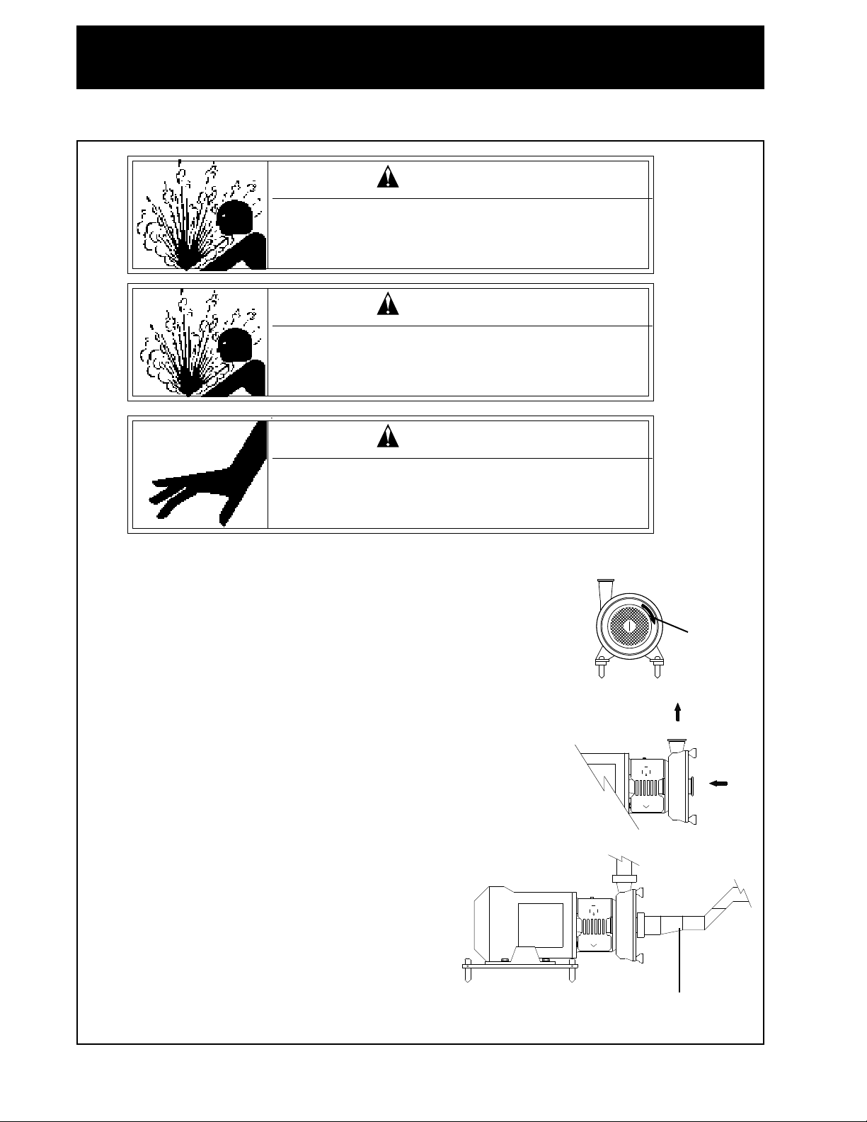
WARNING
Only authorized electricians should connect
the pump.
Mounting surface should be flat and
level.
Legs are adjustable. Legs are not
available on NEMA 300/IEC200
frames and above.
Piping should be supported to avoid
strain on pump casing and front
cover. Pump is designed for either
vertical or horizontal discharge.
If pump is horizontal, mounting the
discharge outlet on top is preferred.
- 8 -
Before starting, bump the motor to check if the motor fan is rotating
clockwise when seen from the motor back. If the motor fan cannot be
seen, look through the seal guard to view the stub shaft. (Bump
means to momentarily apply power to the motor and then immediately
remove power.)
Check the following:
• Flow direction is correct.
• Suction inlet and discharge outlet lines are hooked up correctly.
• All connections are tightened.
Whenpractical,aneccentrictaperedreducershouldbeusedto prevent
air pockets from forming in the lines or in the pump.
Pay attention to circumstances that could lead to pump cavitation:
• Low pressure in the suction line due to line restrictions.
• Air in the suction inlet line.
• Temperature of the fluid being pumped is too
high.
• Pump is oversized for the fluid being pumped.
Ensure that there is a sufficient supply of fluid to
be pumped.
Check the motor for vibration, unusual noises, or
any other abnormalties.
INSTALLATION
OPERATIONAL CHECK
Never run the pump with both the suction side and the
pressure side blocked. This will cause serious
damage to the pump.
Eccentric Tapered
Reducer
Do not operate the pump without the
seal guard in place.
Always check rotation without liquid in
the pump.
WARNING
WARNING
WARNING
Fan Rotation
Motor Back

- 9 -
CLEANING AND REPAIR
Do Not touch the pump when running
the Clean-In-Place procedure.
Lye and nitric acid are poisonous
and can cause burns to skin.
WARNING
WARNING
If the pump is installed in a processing piping system designed for Clean-In-Place (CIP), pump
disassembly is not required. A recommended CIP procedure is included in these instructions.
If CIP is not available, disassemble the pump according to the disassembly instructions provided.
Once disassembled, clean pump parts in an approved cleaning solution(s).
During disassembly and cleaning, inspect all parts for serviceabilty. Replace all parts which show
signs of wear to prevenrt pump failure. Discard all replaced parts in accordance with local, state, or
federal regulations.
The following instructions are for complete pump disassembly and assembly. Use these instructions
as a gude when partial disassembly or assembly is required.
Disassembly/assembly of the pump for repair is identical to disassembly/assembly of the pump for
cleaning. Removal of the pump adapter may not be required.
RECOMMENDED CLEAN-IN-PLACE PROCEDURE
Mixing Cleaning Solution
Only use clean, fresh water to mix nitric acid (HNO3) or caustic soda (NaOH).
Examples:
1% caustic soda (by weight) at 150°F (70°C).
2.5 lbs (1 kg) caustic soda + 30 gal (100 l) water = cleaning solution
1 gal (3.81 l) 33% caustic soda and water + 45 gal (170 l) water = cleaning solution
0.5% nitric acid (by weight) at 150°F (70°C).
0.2 gal (0.751 l) 53% nitric acid and water + 28 gal (105 l) water = cleaning solution
Avoid excessive amounts of cleaning solution.
Adjust the solution flow to the pumping process.
For example, when pumping viscous fluids, increase the flow of cleaning solution.
Always rinse the ump as well as the suction inlet and discharge outlet lines well with clean fresh
water after performing CIP.
MAINTENANCE
- 10 -
MAINTENANCE
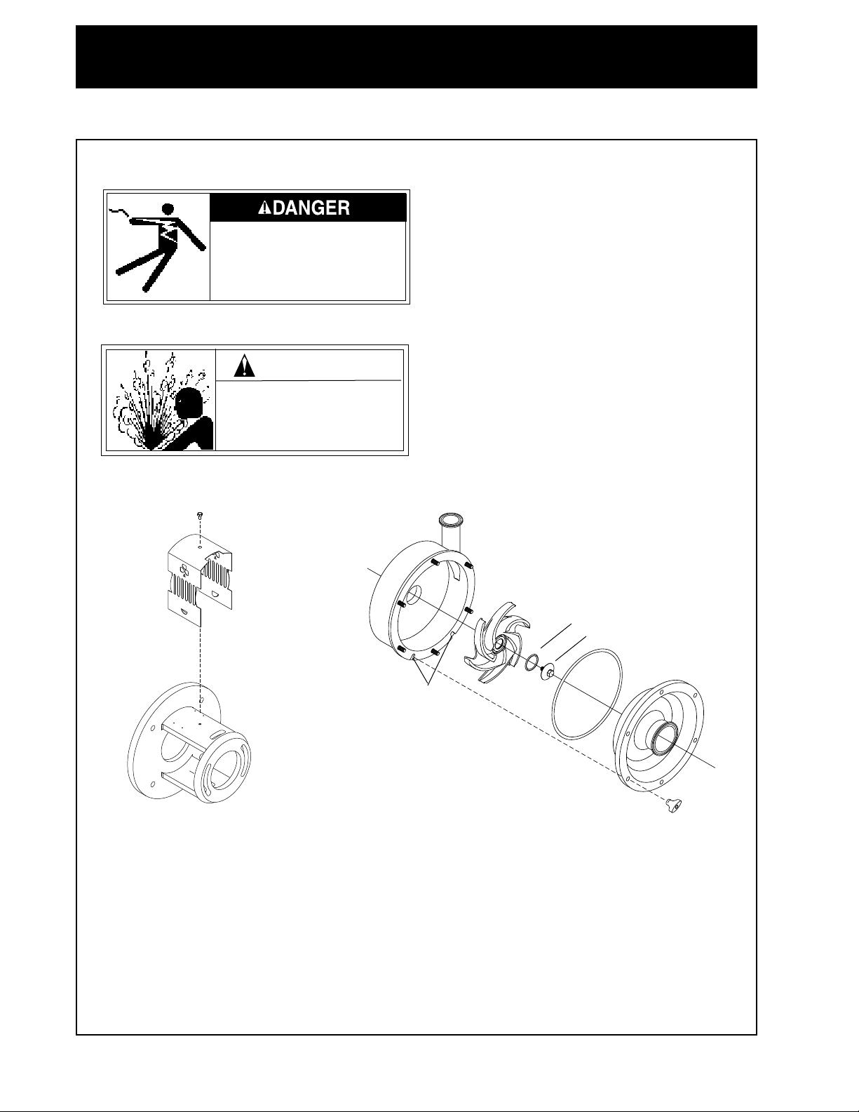
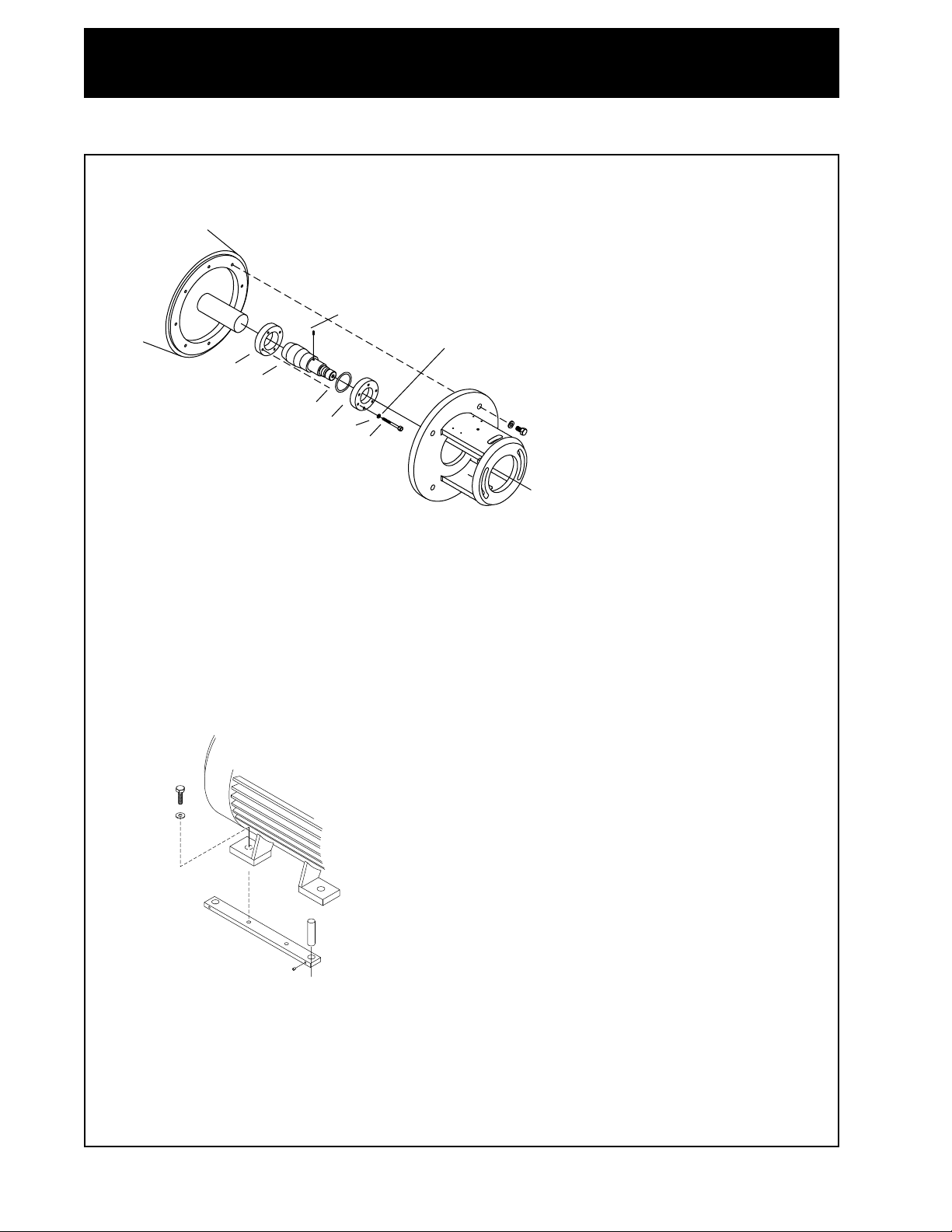
REMOVING PUMP PARTS
DISASSEMBLY
1. Remove seal guard (32) by removing screw (33).
2. Remove wingnuts (6) securing cover (3) to casing (1).
3. Remove front cover (3). Use the two slots in casing (1) and a screwdriver to pry cover off.
4. Remove impeller screw (4) from stub shaft.
5. Unscrew impeller (2) from stub shaft.
6. Remove o-ring (5) on impeller (2) and o-ring (8) on cover as required.
8
3
6
Slot
Relieve pressure and
remove all fluid from pump
prior to disassembly.
4
5
2
1
32
33
WARNING
High voltage. Only an
authorized electrician
should disconnect the
pump.

- 11 -
MAINTENANCE
If disassembling pump with stuffing box and flushing pipes, remove as follows:
1. Remove flushing pipes (24) from stuffing box (22 or 28).
2. Remove casing (1) by removing nuts (13) and washers (14).
3. Remove stuffing box (22 or 28) from casing by removing two screws (23) securing stuffing
box to casing.
STATIONARY SEAL DISASSEMBLY
Disassemble casing as follows:
1. Remove seal gland (10) on back of casing by removing allen screws (9) and washers (38).
2. Remove rear gasket (11), stationary seal (12), and front gasket (11) as required. NOTE: A
rear elastomer gasket is required when using a front PTFE gasket.
1314
1
23
24
22, 28
10
11
12
11
9
1
38

- 12 -
MAINTENANCE
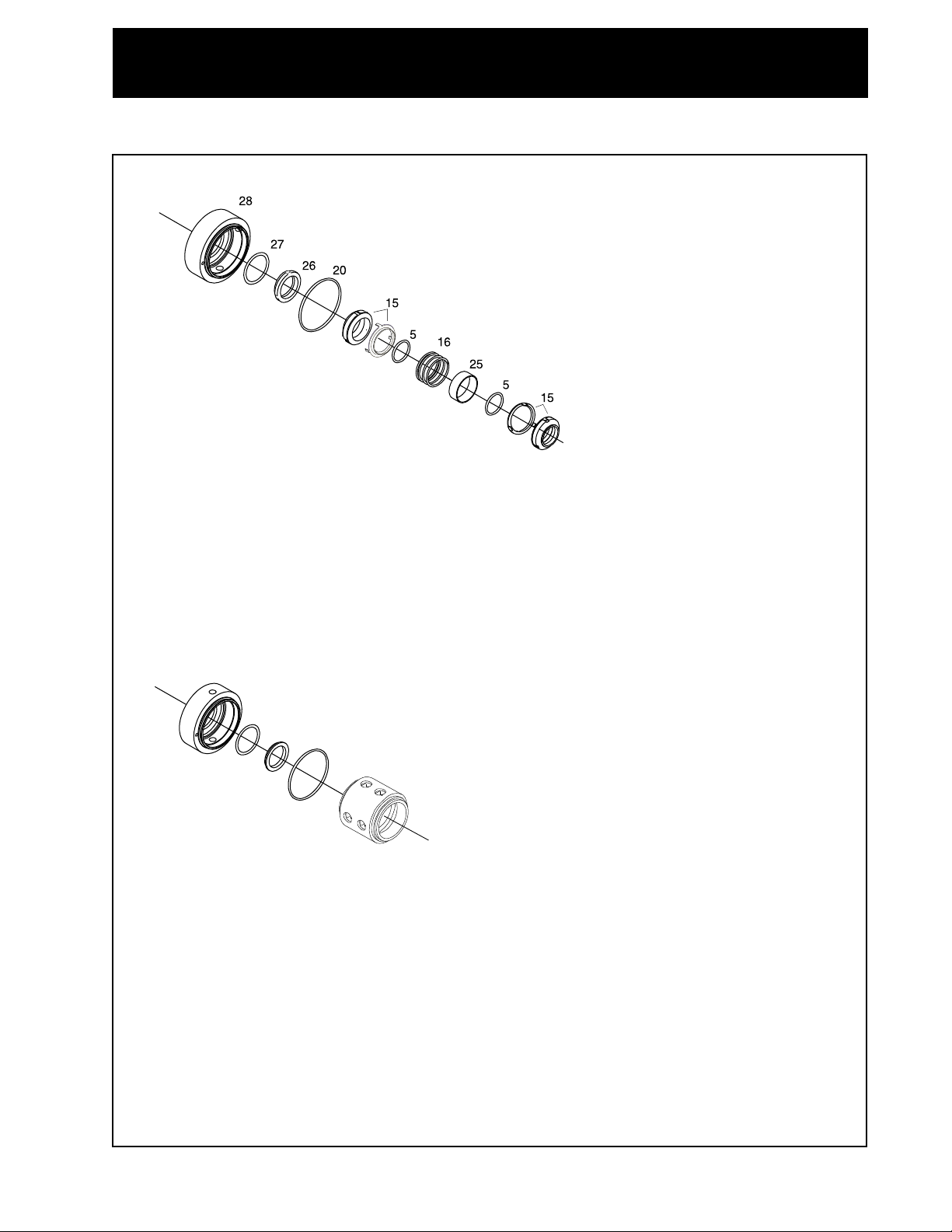
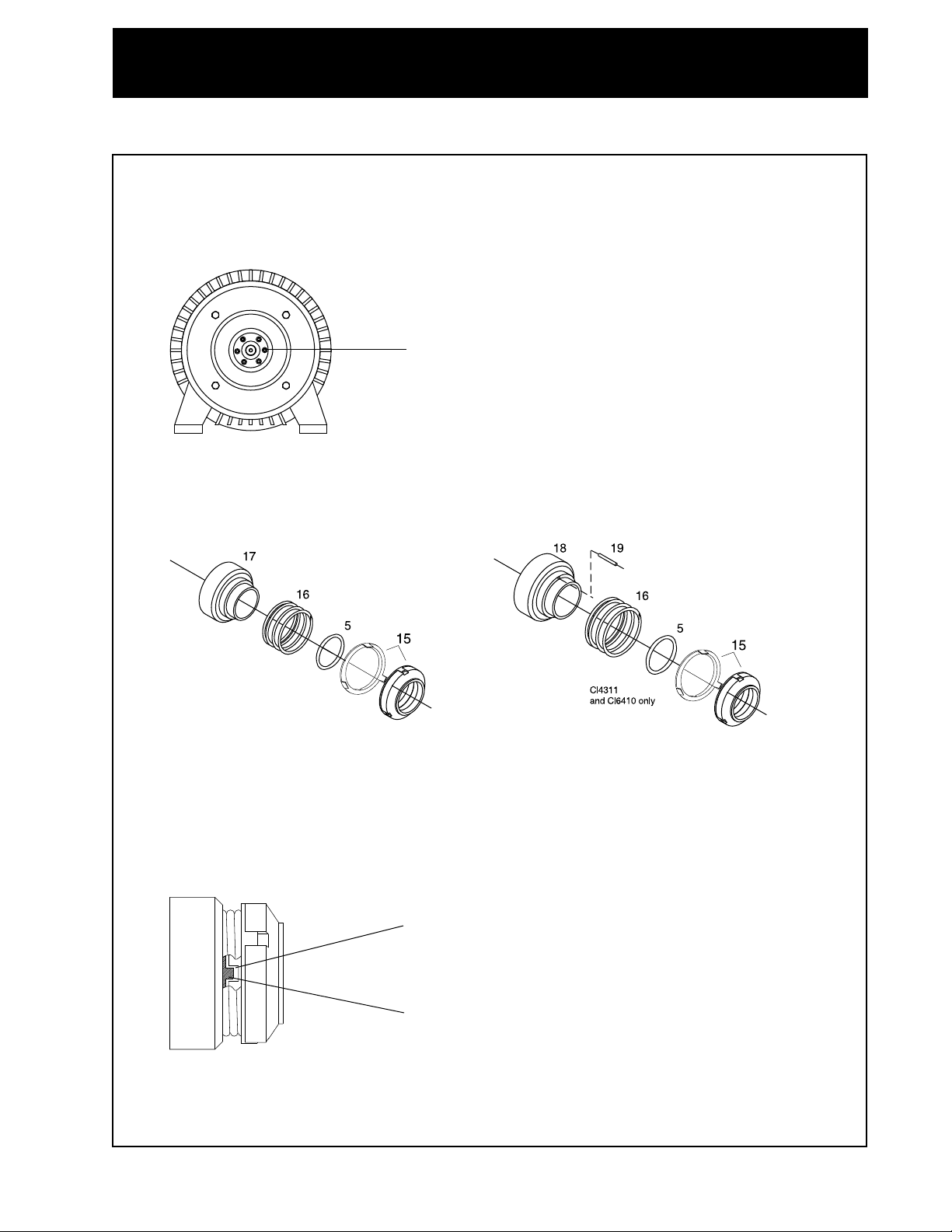
ROTATING SEALS DISASSEMBLY
1. Remove and disassemble seals according to the appropriate configuration shown and described.
Type DG - External Balanced Seal
2. Remove the rotating seal (15), o-ring (5), spring (16) and drive collar (17) from stub shaft.
CL4311 and CL6410: Remove 15, 5, 16, and 18 from the stub shaft. Remove pin (19) as
needed.
Type FG - Water Cooled Single Seal
3. Remove rotating seal (15), o-ring (5), spring (16), and stainless steel drive collar (18) from
stub shaft.
4. Remove pin (19) from stainless steel drive collar as required.
5. Remove o-ring (5) from stainless steel drive collar.
6. Remove o-ring (20) from stuffing box (22).
7. Remove single flush lip seal (21) from stuffing box (22).
- 13 -
Type EG - Water Cooled Balanced Double Seal
1. Remove front rotating seal (15), o-ring (5), spacing ring (25) spring (16), o-ring (5), and rear
rotating seal (15) from stub shaft.
2. Remove rear stationary seal (26) o-ring (27), and o-ring (20) from stuffing box (28).
John Crane Double 8 seal
1. Remove John Crane seal (48) from the from the stub shaft.
2. Remove rear stationary seal (26) o-ring (27), and o-ring (20) from stuffing box (47).
MAINTENANCE
20
26
27
47
48
- 14 -
PUMP PARTS DISASSEMBLY
After the seals are removed and disassembled, remove the following:
1. Remove pump adapter (29) from motor by removing hex head cap screws (30) and washers
(31).
2. Remove compression ring (36), threaded compression ring (35) and retaining ring (40) (used
on 1.5 HP and 2 HP motors only) by removing screws (37) and washers (38). Note that hex
head screws are metric (wrench size is 10mm).
3. Remove pin (39) from stub shaft (34) as required.
4. Remove stub shaft from motor shaft as required.
1. Remove leg brackets (41) from motor (46) by removing hex head cap screws (42) and
washers (43).
2. Remove adjustable legs (45) from leg brackets (41) by removing set screws (44).
MAINTENANCE
30
31
39
34
Screws are metric.
Wrench size is 10mm.
29
38 37
36
40
46
42
43
45
41
44
35

- 15 -
MAINTENANCE
INSPECTION
• Inspect o-rings, seals and gaskets for reuse. Worn o-rings, seals and gaskets should be
replaced.
• Inspect seal faces for scoring or cracks. Replace any seal faces that are damaged.
• Inspect stub shaft and other metal parts for wear or damage.
• Inspect impeller for damage from cavitation. Cavitation damage appears as pitting on the
impeller surfaces.
1. Before assembly, lubricate o-rings and
gaskets with a food grade silicone spray (Tri-
Clover part number L-1011B) or equivalent.
2. It is important that the surface of the rotating
seal be wiped clean of any foreign matter
(dirt, dust, oil from fingers, etc.) prior to
assembly. Clean surface in accordance with
good shop practice.
LEG AND BRACKET ASSEMBLY
Assemble frame parts in reverse order of
disassembly. (See page 14).
PUMP PARTS ASSEMBLY
1. Assemble compression ring (36),
retaining ring (40) (used on 1.5 and 2
HP motors only), and threaded
compression ring (35) onto stub shaft
(34).
2. Place hex head screws (37) and
washers (38) in compression ring.
Start, but do not tighten screws.
3. Place pin (39) in stub shaft as
required. (Pin is not used with the
Type EG and John Crane Double 8 Seal).
Use only Tri-Clover spare parts when
replacing any component of the CL
pump. Use of non-Tri-Clover parts
could result in pump damage or
malfunction.
Rotating Seal Surface
3
/
8
" to
3
/
4
"
35
34
39
40 36
37
38
ASSEMBLY
- 16 -
MAINTENANCE
4. Place stub shaft with parts assembled on motor shaft.
5. Stub shaft should be placed so after the pump adapter is installed, the distance between the
end of the stub shaft and the motor flange on the pump adapter is between3/8” and3/4”.
6. Tighten hex head cap screws evenly but not more than to allow the stub shaft to be moved by
gently tapping with a rubber or plastic tipped mallet. This will allow for possible adjustment
during setting of impeller clearance.
7. Assemble pump adapter (29) to motor with hex head cap screws (30) and washers (31).
Tighten hex head cap screws until tight.
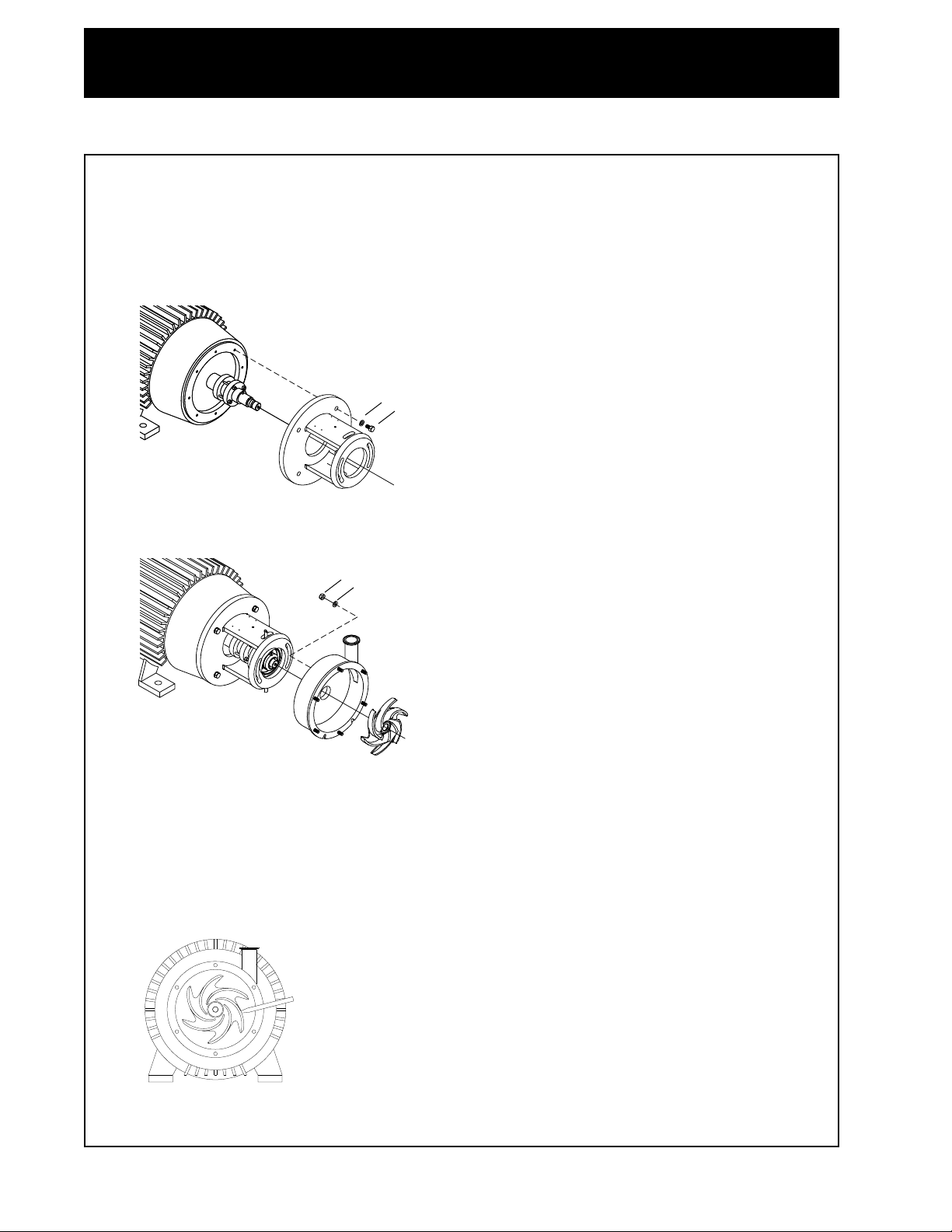
8. Assemble casing (1) to pump adapter with nuts (13) and washers (14). Do not assemble
stationary seal components into casing. These parts should be assembled into casing
after the impeller clearance has been adjusted. Perform impeller clearance adjustment
without seals to prevent any damage to the seals.
9. Screw impeller (2) to stub shaft.
SETTING IMPELLER CLEARANCES WITHOUT SEALS
1. Using a feeler gauge, set the clearance between impeller back and casing to 0.025” - 0.027"
(0.6mm - 0.7mm). CL4311 and CL6410: Set clearance to 0.040" to 0.043" (1mm to 1.1mm).
30
31
29
14
13
1
2
Set clearance to 0.025" - 0.027" (0.4mm - 0.46mm)
CL4311 and CL6410: Set clearance to 0.040" to 0.043" (1mm to 1.1mm)
- 17 -
MAINTENANCE
2. Remove impeller.
3. Remove casing (1) by removing nuts (13) and washers (14).
4. Torque hex head screws (37) securing the compression ring and threaded compression ring to
132 lb-in or 11 lb-ft (15 Nm). Note that hex head screws are metric (wrench size is 10mm).
ROTATING SEALS AND PUMP CASING ASSEMBLY
Type DG - External Balanced Seal
1. If assembling DG type seals, install o-ring (5) into rotating seal (15). Then assemble the rotating
seal (15) and spring (16) onto the drive collar (17).
For the CL4311 or CL6410 pump, insert the pin (19) into the drive collar, and install the o-ring
(5) into the rotating seal (15). Then assemble the rotating seal (15) and spring (16) onto the
drive collar (18).
2. Place the assembled seal on the stub shaft. The drive collar notch must align with the pin on the
stub shaft.
Ensure the drive collar pin enters the notch on the rotating seal cup when the spring is
compressed.
Drive Collar Pin
Notch in Cup
Torque 6 compression ring screws to 132 lb-in or 11 lb-ft
(15Nm). Screws are metric. Wrench size is 10mm.

- 18 -
MAINTENANCE
14
13
9
10 11
12 11
1
2
54
Torque screw to 180 lb-in or 15 ft-lb
(21 Nm).
For the CL4311 and CL6410, torque
screws to 30 ft-lb (41 Nm).
3. Install front gasket (11), stationary seal (12), rear gasket (11) and seal gland (10) into casing
(1) using allen screws (9). Torque the screw to 72 lb-in (8 Nm). For the CL4311 and the
CL6410, torque the screw to 60 lb-in (7 Nm). NOTE: A rear elastomer gasket is required
when using a front PTFE gasket.
4. Install casing (1) to pump adapter with nuts (13) and washers (14). Tighten nuts and
washers.
5. Screw impeller (2) to stub shaft.
6. Install o-ring (5) in impeller.
7. Install impeller screw (4) on stub shaft. Torque impeller screw to 180 lb-in or 15 lb-ft (21Nm).
For the CL4311 and CL6410, torque the impeller screw to 30 ft-lb (41Nm).
Type FG - Water Cooled Single Seal
1. Using a proper press fitting tool, (OD should be 2.913”), install single flush lip seal (21) into
stuffing box (22) with beaded edge up. Make certain the lip seal is completely seated in
the gland in the stuffing box.
Note: It is not necessary to use a press fitting tool to install the lip seal on the 4311 and 6410
pumps. Install the lip seal beaded edge up, making certain the seal is completely seated in
the gland in the stuffing box.
2. Install o-ring (20) into stuffing box (22).
22
21
20
2.913" OD press
fitting tool
Torque screw to 72 lb-in (8 Nm).
For the CL4311 and CL6410,
torque screws to 60 lb-in (7 Nm).

- 19 -
3. Install front gasket (11), stationary seal (12), rear gasket (11) and seal gland (10) into
casing (1) using Allen screws (9) and washers (38). Torque the screws to 72 lb-in (8
Nm). For the CL4311 and the CL6410, torque the screws to 60 lb-in (7 Nm). NOTE: A
rear elastomer gasket is required when using a front PTFE gasket.
4. Install two screws (23) securing stuffing box (22) to casing.
5. Install pin (19) into stainless steel drive collar (18) as required.
6. Install o-ring (5) into stainless steel drive collar (18).
7. Install o-ring (5) into rotating seal (15).
8. Install spring (16) onto rotating seal (15) and onto stainless steel drive collar (18).
MAINTENANCE
38
9
20
22
10
11
12
11
1
23
Torque screws to 72 lb-in (8 Nm).
For the CL4311 and 6410, torque screws to 60 lb-in (7 Nm).

- 20 -
MAINTENANCE
9. Install the stainless steel drive collar (18) with the spring (16) and rotating seal (15) onto the
stub shaft.
Ensure the drive collar pin enters the notch on the rotating seal cup when the spring
is compressed.
10. Slide the seal installation tool (50) over the stub shaft, tapered end out, until it abuts with
the shoulder of the stub shaft. (This tool can also be used for disassembly to protect the
seals.)
11. Check to make certain lip seal is still seated correctly. Slide casing (1) with the assembled
seals over installation tool and onto the stub shaft.
12. Remove seal installation tool (50).
13. Install casing (1) to pump adapter with nuts (13) and washers (14). Tighten nuts and
washers.
14. Screw impeller (2) to stub shaft.
15. Install o-ring (5) in impeller.
16. Install impeller screw (4) on stub shaft. Torque impeller screw to 180 lb-in or 15 lb-ft (21
Nm). For the CL4311 and the CL6410, torque the impeller screw to 30 lb-ft (41 Nm).
17. Install flushing pipes (24) to stuffing box.
Notch in Cap
Drive Collar Pin
This manual suits for next models
10
Table of contents
Other Tri-Clover Water Pump manuals


Popular Water Pump manuals by other brands


Wilo
Wilo Wilo-E 15/1-5 Installation and operating instructions

Interpump Group
Interpump Group Pratissoli WK Series Repair manual

Blue Angel
Blue Angel DF12VSM Operating instructions and parts manual

GUSHER PUMPS
GUSHER PUMPS Vortex Series instruction manual
 Use and maintenance instruction manual")
Aqua
Aqua HC151+ pH (RX) Use and maintenance instruction manual

Goulds Pumps
Goulds Pumps DWT Installation, operation and maintenance instructions