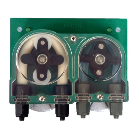
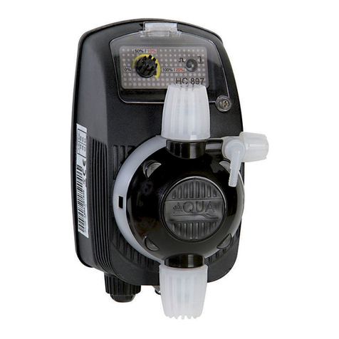
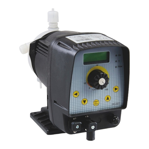
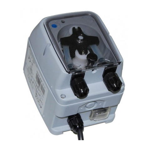
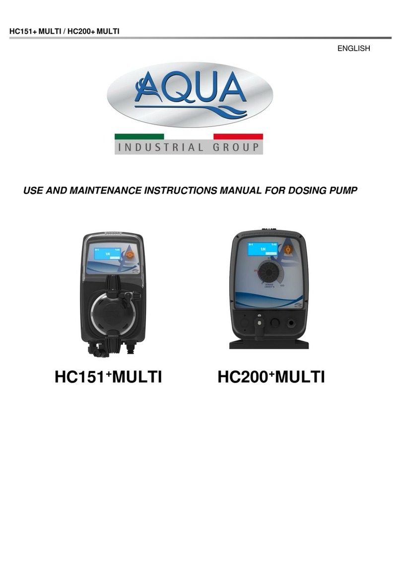
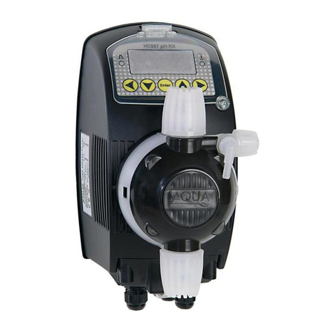
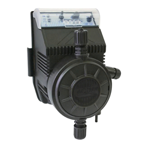
Aqua HC151+ pH (RX) User guide

HC151+ pH(Rx)-Cl(J) / HC200+ pH(Rx)
ENGLISH
USE AND MAINTENANCE INSTRUCTIONS MANUAL
FOR DOSING PUMP
HC200+pH(Rx)

HC151+ pH(Rx)-Cl(J) / HC200+ pH(Rx)
ENGLISH

HC151+ pH(Rx)-Cl(J) / HC200+ pH(Rx)
ENGLISH
INDEX
1. GENERAL RULES..................................................................................................................................... 4
1.1 INSTALLATION STANDARDS ........................................................................................................... 4
2. OPERATION .............................................................................................................................................. 5
2.1 OVERALL DIMENSIONS.................................................................................................................... 5
2.2 TECHNICAL FEATURES.................................................................................................................... 5
2.3 HYDRAULIC FEATURES ................................................................................................................... 6
2.4 PERFORMANCE GRAPHS................................................................................................................ 7
2.5 CONTENT OF THE PACKAGE (Standard version) ........................................................................... 7
3. HC151+pH(Rx)-Cl(J) / HC200+pH(Rx) .................................................................................................... 8
3.1 HC151+/HC200+PUMP CONTROLS................................................................................................. 8
3.2 HOW TO NAVIGATE THROUGH THE MENUS................................................................................. 9
3.3 FIRST PUMP INITIALIZATION......................................................................................................... 10
3.4 GETTING STARTED......................................................................................................................... 11
3.4.1 Priming....................................................................................................................................... 11
3.4.2 Pump calibration ........................................................................................................................ 12
3.5 PUMP SETUP................................................................................................................................... 13
3.5.1 SETPOINT menu....................................................................................................................... 13
3.5.2 CALIBRATION menu................................................................................................................. 15
3.6 CORRELATION BETWEEN FREE CHLORINE, pH e REDOX ....................................................... 18
3.7 SETTINGS ........................................................................................................................................ 19
3.7.1 General e Security ..................................................................................................................... 19
3.7.2 General > Proximity sensor ....................................................................................................... 20
3.7.3 Generals > Temperature probe ................................................................................................. 21
3.7.4 Generals > Measure startup delay............................................................................................. 22
3.7.5 General > Energy saving ........................................................................................................... 22
3.7.6 Security > Password.................................................................................................................. 23
3.7.7 Security > Level Input Polarity ................................................................................................... 23
3.7.8 Security > Low Level Delay ....................................................................................................... 24
3.7.9 Security > Over Feed Alarm (OFA)............................................................................................ 24
3.7.10 Security > Factory Settings restore............................................................................................ 25
3.8 STATISTICS...................................................................................................................................... 26
4. DOSING PUMPS INSTALLATION RULES............................................................................................. 27
5. ELECTRICAL CONNECTIONS............................................................................................................... 28
5.1 HC151+ PImA model pump .............................................................................................................. 28
6. TROUBLESHOOTING............................................................................................................................. 29
6.1 PROBLEM –CAUSE –SOLUTION.................................................................................................. 29
7. MAINTENANCE....................................................................................................................................... 29
8. WARRANTY............................................................................................................................................. 29
EXPLODED VIEWS ........................................................................................................................................ 30

HC151+ pH(Rx)-Cl(J) / HC200+ pH(Rx)
ENGLISH
1. GENERAL RULES
Carefully read the warnings listed below as they provide important information regarding the rules for
installation, use and maintenance.
Please keep this manual carefully for further reference.
1.1 INSTALLATION STANDARDS
Install the dosing pump so that it is easily accessible whenever maintenance is required. Never
obstruct the place where the dosing pump is located.
The servicing and maintenance of the dosing pump and all its accessories must always be carried out
by qualified personnel.
AQUA SpA cannot be held responsible for damage to persons or things caused by poor installation or
incorrect use of the dosing pump.
Check that the ground is fully functional and corresponds to the regulations in force. Make sure
there is a high sensitivity differential switch (0.03 A). Check that the pump ratings are compatible
with those of the mains supply. Never install the pump directly in parallel with inductive loads
(eg motors / solenoid valves) but if necessary use an "insulation relay". Inside the pump there
are two protections: a varistor and a fuse.
THE EQUIPMENT, SUBJECT TO THIS DOCUMENT, ARE NOT INTENDED TO BE
INSTALLED AND USED IN EXPLOSIVE ATMOSPHERE ENVIRONMENTS. IT ISN’T
AN ATEX PUMP.
P: dosing pump
R: relay
I : Switcher or multi-pole
security device
E: Motor or generally
inductive charge
A: supply voltage

HC151+ pH(Rx)-Cl(J) / HC200+ pH(Rx)
ENGLISH
2. OPERATION
The HC151+ / HC200+ pH(Rx)-CL(J) digital pumps are solenoid dosing pumps with integrated measuring
controller that can monitor and modify the chemical-physical parameters (such as pH, redox or chlorine) of the
water to be treated. The pumps have two BNC connectors: one for pH or Redox electrode connection, the
other for connecting a level sensor. For the connection of a Chlorine sensor, the pump is equipped with a 4-
way connector. The pump is also designed to connect a PT100 temperature sensor and a proximity sensor
(not included in the package) to monitor the temperature and the presence of flow inside an electrode holder.
2.1 OVERALL DIMENSIONS
HC151+
HC200+
2.2 TECHNICAL FEATURES
Power supply: 100÷240VAC ± 10% –50/60Hz
Insulation Class: CLASS I
Absorbed power: see “2.3 - Hydraulic Features”
Fusible: 2 A –RIT
Protection Grade: IP65
Environmental conditions: Closed environment, altitude up to 2000m, room temperature from
5°C up to 40°C, maximum relative humidity 80% (linearly decreases
until it is reduced to 50% at 40°C).

HC151+ pH(Rx)-Cl(J) / HC200+ pH(Rx)
ENGLISH
2.3 HYDRAULIC FEATURES
SOLENOID
TYPE
FLOW RATE
PRESSURE
STROKES
INJECTION
VALUE
ABSORBED
POWER
l/h
bar
spm
ml/stroke
Watt
60
A
1
7
100
0,17
14
5
1
0,83
14
B
3
7
150
0,33
14
9
1
1
14
C
5,5
6
180
0,51
14
10
1
0,93
14
70
A
1,8
20
75
0,40
16
4
1
0,89
16
B
4
12
120
0,56
16
7
1
0,97
16
C
5,8
9
180
0,54
16
14
1
1,30
16
80
(only HC151)
A
4
20
150
0,44
22
8
1
1,11
22
B
8
12
200
0,54
22
15
1
1,08
22
C
13,5
5
300
0,75
22
24
1
1,11
22
The above data refer to tests carried out with water at room temperature. Values can fluctuate by 10%.
Chemicals with viscosity different than water or with supply voltages and / or frequencies other than 230Vac
/ 50Hz, the flow rate may also have significant variations.

HC151+ pH(Rx)-Cl(J) / HC200+ pH(Rx)
ENGLISH
2.4 PERFORMANCE GRAPHS
2.5 CONTENT OF THE PACKAGE (Standard version)
▪HC151+or HC200+pump
▪User’s manual
▪Injection valve PVDF-CE-VT
▪Foot filter PVDF-PTFE-VT
▪2 meters PE discharge tube
▪2 meters PVC suction tube
▪2 meters PVC bleed valve tube (2 m)
▪Fixing bracket (only for HC151+)
▪Set of screws and plugs for wall mounting

HC151+ pH(Rx)-Cl(J) / HC200+ pH(Rx)
ENGLISH
3. HC151+ pH(Rx)-Cl(J) / HC200+ pH(Rx)
3.1 HC151+/HC200+PUMP CONTROLS
The control panel of the HC151+ pH(Rx)-Cl (J) and HC200+ pH(Rx) pump is composed of a graphic
display (1) and an encoder knob (2) which allow you to navigate through the various menus and select
/ modify the parameters of the pump. The figures below, show what the control panel looks like:
HC151+
A. Active function;
B. Configured parameters;
C. Time;
D. Warnings messages
E. Setpoint
HC200+
1. 132x56 pixel graphic display;
2. Encoder;
3. Mechanical stroke lenght adjustment
(only for HC200+)
Press to: confirm
a value or access
a submenu. If it is
kept pressed for 2
seconds, it returns
to the previous
menu or activates
/ deactivates the
Stand-by.
Turn to: navigate
the menus or
change a numeric
value.

HC151+ pH(Rx)-Cl(J) / HC200+ pH(Rx)
ENGLISH
3.2 HOW TO NAVIGATE THROUGH THE MENUS
The pump has been designed so the programming phases are user friendly, for this purpose the control
area has a large backlit graphic display and a rotary encoder with an integrated button function.
A navigation diagram of the menus on the pump is shown below:
From the Homescreen:
This is the menu where all the main
configurations for a correct pump
operation are performed.
This is the menu in which basic
operations are performed, such as
choosing the language or setting the
system time.
This is the menu where information on
pump operation, such as stroke count
calibration stats can be viewed.
3.5
3.7
3.8

HC151+ pH(Rx)-Cl(J) / HC200+ pH(Rx)
ENGLISH
3.3 FIRST PUMP INITIALIZATION
The first time the pump is switched on, some basic parameters must be set, such as the language in
which the programming menus will be displayed, the date and time of the system and other basic
settings.
Below is a diagram of what appears when the unit is first turned on:
Choose mode
A, Bor C
performance
you want
according to the
table on
Paragraph 2.3.

HC151+ pH(Rx)-Cl(J) / HC200+ pH(Rx)
ENGLISH
3.4 GETTING STARTED
3.4.1 Priming
Once the basic parameters of the pump have been set, it is suggested to carry out the priming: this
operation is used to "prime" the metering pump (i.e. fill the chamber between the membrane and the
pump body and remove any air bubbles present inside the suction and discharge tubes) and make it
ready to dose the chemical in the plant.
Before proceeding with priming, make sure you have connected the delivery and suction tubes to the
pump body as well as the air purge tube included in the supply (for the connection, follow the image
shown below:
For priming, follow the steps below:

HC151+ pH(Rx)-Cl(J) / HC200+ pH(Rx)
ENGLISH
3.4.2 Pump calibration
Once the priming procedure is complete, the quantity of ml (milliliters) per stroke that the pump is able
to supply must be defined, this information is necessary for a correct dosage of the chemical and
essential if you want to use the PPM function described in the "PUMP SETUP" paragraph.
ATTENTION: in order to use this function, the pump MUST be primed.
To calibrate the pump, follow the steps below:
1. Make sure that the pump has
been installed on the plant and
it has been primed using the
function described in the
previous paragraph (§
3.4.1)
2. Connect the suction tube
(complete with foot filter) into a
BEKER-type test tube
graduated in ml (milliliters);
3. Fill the test tube until reaching
the maximum limit with the
chemical product that will be
used during the normal
operation of the pump;
4. Power up the pump, enter the
SETTINGS > GENERAL
MENU, follow the instructions
on the display: enter the
maximum value of the beker by
turning the encoder knob, then
press the knob to confirm;
5. Set the number of strokes the
pump will perform;
6. Once the button has been
pressed to confirm, the pump
will start for the number of
strokes set;
7. At the end, check how much
chemical is left in the beker and
write down this value on the
display using the knob, finally
press to confirm this value;
8. the next screen will show the
value calculated by the pump in
ml per stroke.
9. To exit the calibration
function, keep the button
pressed for 2 seconds.

HC151+ pH(Rx)-Cl(J) / HC200+ pH(Rx)
ENGLISH
3.5.1
3.5.2
3.5 PUMP SETUP
Within this menu, you can choose whether to set the working point (setpoint) or calibrate the probes
connected to the pump.
The complete list of available functions is shown below:
3.5.1 SETPOINT menu
This function allows you to program the working point (Setpoint) and to program the proportional
dosage according to the value of the measurement read.
Here are the steps to set up this feature:
This menu allows you to program the
operating point (setpoint) and the
intervention mode to which the pump
must refer.
This menu allows you to calibrate the
probes connected to the pump and to
know the operating status of the probe
itself.
Eg pH: dosing of an ACID chemical:
Setpoint: 7.20 pH
Window width limit: 7.60 pH (e.g. 120
strokes / min);
For values equal to or lower than the
Setpoint, the pump is stopped;
The pump works at maximum frequency for
values equal to or greater than the set
window width limit, the frequency
decreases as the pH value decreases until
it stops at the Setpoint.
ATTENTION: the pump can also be programmed for the
dosage of an Alkaline chemical product but it is necessary to
check that the seals in the pump body (in Viton for the standard
version) are chemically compatible with the product to be
dosed.

HC151+ pH(Rx)-Cl(J) / HC200+ pH(Rx)
ENGLISH
Setpoint Redox:
Setpoint of Chlorine:
Es. Chlorine:
Setpoint: 1.20 ppm
Window width limit: 0.80 ppm (es. 120 strokes/minute);
For values equal to or higher than the Setpoint, the pump is stopped;
The pump works at maximum frequency for values equal to or lower than
the set window width limit, the frequency decreases as the Setpoint value
approaches.
ATTENTION: the pump can also be programmed for the
dosage of a Reductive chemical product but it is necessary to
check that the seals in the pump body are chemically
compatible with the product to be dosed.
Es. Redox: dosing of an OXIDANT
chemical:
Setpoint: 750 mV
Window width limit: 650 mV (es. 120
strokes/minute);
For values equal to or higher than the
Setpoint, the pump is stopped;
The pump works at maximum frequency for
values equal to or lower than the set
window width limit, the frequency
decreases as the setpoint value
approaches.

HC151+ pH(Rx)-Cl(J) / HC200+ pH(Rx)
ENGLISH
3.5.2 CALIBRATION menu
In order to obtain a precise measurement of the chemical-physical parameters of the water of the
plant to be treated, it is necessary, during the installation, to calibrate the probes (pH, Redox or
Chlorine).
pH probe calibration
For proper calibration follow the steps described below:
To calibrate the pH electrode, you need
two buffer solutions, one at pH 7 and the
other at pH 4 or pH 9.
It would be important to measure the
temperature of the buffer solution and
check the corresponding value on the
label of the solution itself; if this
measurement cannot be made, skip this
step and proceed to the next;
Connect the BNC connector of the
electrode to the relative input on the
bottom of the pump (refer to the drawing
on paragraph 5 to identify its position);
Remove the protective cap of the
electrode then wash it with water and dry
it;
Enter in Calibration menu and follow the
instructions on the display: dip the
electrode in the first buffer solution at pH
7, wait for the measurement to stabilize,
if necessary, modify the value read on
the display with one on the solution (it
can happen that the measurement does
not correspond perfectly to the solution,
this is perfectly normal). Press on the
encoder to confirm this value;
Remove the electrode from the first
solution and wash it with water, dry it
then dip in the second buffer solution at
pH 4 (or pH 9); wait for the measurement
to stabilize, if necessary, modify the
value read on the display with the one on
the on the solution. Press on the
encoder to confirm the value;
At the end of the procedure, the quality
of the electrode will be shown on the
display.
For values between 25% and 0% we
suggest replacing the electrode.

HC151+ pH(Rx)-Cl(J) / HC200+ pH(Rx)
ENGLISH
Redox probe calibration
For proper calibration follow the steps described below:
To calibrate the Redox electrode it is
necessary to have a buffer solution with
a known value (for this example the
475mV solution was used).
Connect the BNC connector of the
electrode to the relative input on the
bottom of the pump (refer to the drawing
on paragraph 5 to identify its position);
Remove the protective cap of the
electrode then wash it with water and dry
it;
Enter in Calibration menu and follow the
instructions on the display: dip the
electrode in the 475mV buffer solution,
wait for the measurement to stabilize, if
necessary, modify the value read on the
display with the one on the solution (it
may happen that the measurement does
not correspond perfectly to solution, this
is perfectly normal). Press on the
encoder to confirm this value;
At the end of the procedure, the quality
of the electrode will be shown on the
display.
For values between 25% and 0% we
suggest replacing the electrode.

HC151+ pH(Rx)-Cl(J) / HC200+ pH(Rx)
ENGLISH
Chlorine probe calibration (HC151 + only)
For a correct calibration follow the steps described below:
To calibrate the Chlorine probe it is
necessary to have a photometer and a
DPD test kit.
Connect the 4-pole connector of the
probe to the relative input on the bottom
of the pump (refer to the drawing on
paragraph 5 to identify its position);
Install the probe inside the modular
probe holder and regulate the flow of
water with a constant flow rate of not
more than 60 l / h and not less than
30 l / h;
Wait for the polarization of the probe
(this can also take several hours: from 1
to 24), the probe manufacturer suggests
to wait up to 6 hours before performing
the calibration;
ATTENTION: if the Pt-Cu probe is
used to determine the free chlorine,
the polarization times are reduced to
about 1 hour.
Access the Calibration menu and follow
the instructions on the display: take a
water sample and use the DPD test kit
and photometer to determine the
Chlorine value, modify the value read on
the pump display with the value detected
by the photometer. Press on the
encoder to confirm this value;
ATTENTION: for the membrane
chlorine probe (ppm-mV or ppm-mA)
follow the probe manufacturer's
instructions for the mandatory
preliminary operations before being
able to connect it to the pump;

HC151+ pH(Rx)-Cl(J) / HC200+ pH(Rx)
ENGLISH
3.6 CORRELATION BETWEEN FREE CHLORINE, pH e REDOX
The graph shown below is useful for understanding the correlation between the measurement of free
Chlorine the pH and Redox. In a swimming pool system this information is very useful to verify that there
is an "alignment” of all the measures to ensure that the chemical-physical parameters are respected; to
better understand the graph, a typical example is described:
The area highlighted in light blue is the one that indicates the ideal values in a swimming pool system.
For example: for pH value of 7.2 (ideal), a Redox value of 725mV corresponds, corresponding to a free
Chlorine value of 1.2ppm.

HC151+ pH(Rx)-Cl(J) / HC200+ pH(Rx)
ENGLISH
3.7 SETTINGS
3.7.1 General e Security
The settings menu is divided into two categories: General Settings and Security Settings: in General
Settings you will find all those basic settings encountered during the pump initialisation, such as the
choice of language, the setting of the date / time, the pump performance, etc.
In the Security settings, on the other hand, there are settings such as the choice of the protection
password, the delay in activating the level alarm, etc.
All possible settings are listed below:

HC151+ pH(Rx)-Cl(J) / HC200+ pH(Rx)
ENGLISH
3.7.2 General > Proximity sensor
This function allows you to enable / disable the proximity sensor (not supplied with the pump) which
provides, if enabled, the presence or absence of the passage of water inside the electrode holder
modules (which need to function correctly of an adequate flow). If there is no flow, the display will
show the flashing * FLOW * message.
Here are the steps to set up this feature:
Proximity sensor connection
This manual suits for next models
2
Table of contents
Other Aqua Water Pump manuals

Aqua
Aqua HC 201 Installation manual

Aqua
Aqua HC 200 Installation manual

Aqua
Aqua HC150 Series User manual

Aqua
Aqua HC151 PH-RX Installation manual

Aqua
Aqua LIPARI Manual

Aqua
Aqua TEC-2VV User manual

Aqua
Aqua DET 2 User manual

Aqua
Aqua GERMAC G650 User manual

Aqua
Aqua HC151+ CI(J) User manual

Aqua
Aqua APP-C Series User manual