TriangleTube PSRKIT38 User manual

Burner Head Replacement Kit
for PRESTIGE SOLO 399
1
Kit Part Number: PSRKIT38
Parts List (Fig.1)
1. Burner Head
2. Burner Head Gasket
3. 8 -Stainless Steel Phillips Screws. (For attach-
ing the new burner head to the burner mounting
plate.)
Recommended tools:
A. Pipe
Wrench.
B. Phillips Screw Driver.
C. 10 mm Socket and/or 10 mm Wrench.
D. Flat Blade Putty Knife.
Indicates a potentially hazardous situation
which, if ignored, can result in serious
injury or substantial property damage.
For your safety, turn off electrical power
supply at service panel and allow unit to cool
before proceeding. Failure to do so can cause
severe personal injury or death.
Indicates special instructions on installa-
tion, operation or maintenance, which are
important to equipment but not related to
personal injuryhazards.
Failure to follow instructions below can result
in severe personal injury or damage if ignored.
•Instructions are for a qualified installer/ ser-
vice technician.
• Read all instructions before proceeding.
•Follow instructions in proper order.
WARNING
NOTICE
WARNING
WARNING
3
2
1
Fig. 1: Burner Head & Gasket

Burner Head Replacement Kit
for PRESTIGE SOLO 399
Instructions:
1. Turn power to the unit “OFF” and allow unit
to cool.
2. Shut off gas supply to the inlet of the unit at
the external main manual shutoff valve to
the unit.
3. Remove front door and disconnect the gas
supply piping to the PRESTIGE at the brass
union near inlet of the gas valve.
4. Disconnect the solenoid wiring from the gas
valve
5. Disconnect the ignition cable and remove
the ground wire at the ignitor.
To ease the removal of the blower, venturi
and gas valve assembly, remove the top jack-
et access panel.
6. Remove the two electrical quick connects on
blower and four 10 mm nuts securing the
blower to the burner mounting plate. Remove
blower, venturi and gas valve by lifting up
and pulling forward on the assembly.
7. Remove the six 10 mm nuts securing the
burner mounting plate to the heat exchanger
body. Remove the burner, blower and gas
valve from the heat exchanger all as one
unit.
Use care in removing the burner assembly
not to crack or damage the combustion
chamber insulation. See WARNING on page
5for instructions on handling the combus-
tion chamber insulation.
8. Loosen the eight Phillips head screws
attaching the burner head to the burner
mounting plate. Remove and discard the
old burner head and burner head gasket.
If the gasket “sticks” to the burner plate use
aflat blade putty knife to remove any gasket
material. Ensure not to scratch or score the
mating surface.
NOTICE
NOTICE
NOTICE
2
Burner
Head
Burner
Mounting Plate
Burner Head
Gasket
10 mm
Mounting
nuts
Ignitor with
ground wire
Gas Piping
Union
Combustion
Chamber Insulation
Fig. 2: Burner Assembly
Fig. 3: Burner Head and Gasket Assembly

Burner Head Replacement Kit
for PRESTIGE SOLO 399
3
For the reassembly process do not use adhe-
sives on ANY gasket surface.
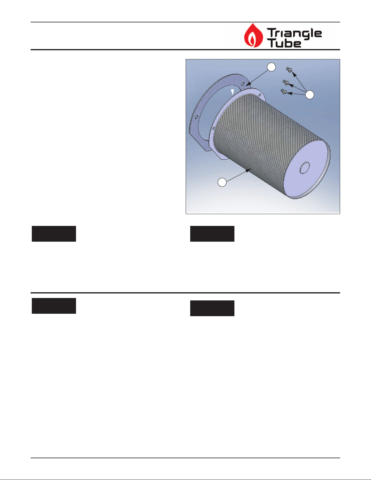
9. With the new gasket in place attach the new
burner head to the burner mounting plate,
using the 8 screws supplied in the kit.
10. Re-insert the burner plate and burner assem-
bly onto the heat exchanger body. Carefully
align the burner assembly and ignitor with
the combustion chamber insulation to avoid
insulation damage, as shown in Fig. 2.
11. Hand tighten the 10 mm nuts to hold the
burner assembly in place.
12. Using a wrench tighten each nut until gasket
is slightly compressed.
Do not over tighten. Pinching or tearing of the
burner plate gasket may occur causing the
possible escape of combustion gases from the
combustion chamber resulting in death, seri-
ous injury or substantial property damage.
13. Re-install the blower,venturi and gas valve
assembly by reconnecting the two electrical
quick connects on blower. Re-attach and
tighten the assembly to the burner mounting
plate using the four 10 mm nuts removed in
step 6.
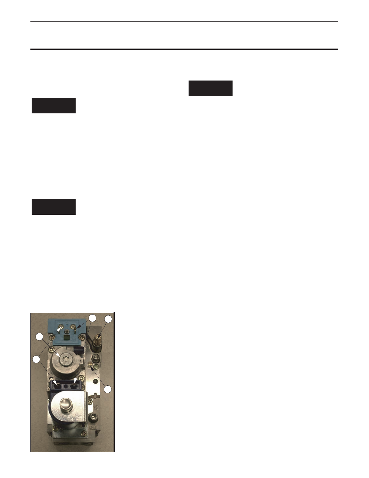
14. Re-attach the ignition cable and the ground
wire to the ignitor.
15. Reconnect the solenoid wiring to the gas
valve. As shown in Fig. 4
16. Reconnect and tighten the gas pipe union
before placing the PRESTIGE unit back
into operation. Check and test all gas con-
nections for leaks. Repair leaks if found.
Do not check for gas leaks with an open flame.
Use a bubble test. Failure to check for gas
leaks can cause severe personal injury, death
or substantial property damage.
17. Turn on gas supply to the inlet of the unit at
the external main manual shutoff valve to
the unit.
18. Turn power to the unit “ON”. The unit is
now ready to be placed back into service.
19. It is recommended that the installer per-
forms a complete combustion test to ensure
the combustion levels, in Table 1. are met at
HIGH fire and the burner is operating at
optimum conditions.
The combustion testing and adjustments
must be performed by a qualified installer,
service agency or the gas supplier.All com-
bustion measurements must be perform with
calibrated equipment to ensure proper read-
ings and accuracy.
Failure to perform a complete combustion
test at high input rate may result in incom-
plete combustion and the production of car-
bon monoxide, which can cause severeper-
sonal injury,death or substantial property
damage.
WARNING
WARNING
WARNING
WARNING
NOTICE
Table 1: Recommended Combustion Levels
Natural Gas Propane
O2 Min. 2.30% 3.70%
O2 Max. 4.50% 5.20%
CO2 Min 9.30% 10.00%
CO2 Max 10.50% 11.00%
CO Max 100 ppm 100 ppm

20. Manually place the boiler into HIGH fire mode
by pressing the MODE button with “+” button
simultaneously on the control panel display
while in the STANDBY (STBY) mode.
The control panel will display a H followed
by the current boiler temperature when
placed into high fire test mode.
21. If the combustion levels during high fire are out-
side the recommended combustion settings
adjust the THROTTLE SCREW (see Fig. 4)
using a flat-blade screwdriver.
The throttle screw is highly sensitive and
requires the use of a combustion analyzer for
adjustment. An adjustment as small as an 1/8 of
aturn can produce a large change in combustion
levels.
22. Once the combustion level is set at high fire,
manually place the boiler into LOW fire mode
by pressing the “MODE” and “-” buttons simul-
taneously on the control display while in the
STANDBY (STBY) mode.
The control panel will display a L followed by the
current boiler temperature when placed into low
fire test mode.
23. If the combustion level during low fire is not
within +/-0.4% of the combustion level mea-
sured at high fire, adjust the offset screw below
the cap on the gas valve.
Counter-clockwise adjustment of the Offset
Screw at High Fire:
O2 increases and CO2 decreases
Clockwise adjustment of the Offset Screw at
High Fire:
O2 decreases and CO2 increases
24. Reverify combustion level measurements at
both high and low fire, readjust if necessary.
NOTICE
WARNING
NOTICE
Burner Head Replacement Kit
for PRESTIGE SOLO 399
4
3
4
2
1
6
Fig. 4: Gas Valve Wiring &
Combustion Adjustment
1. Brown wire
2. Blue wire
3. Throttle screw
4. Offset screw
5. Ground, “Open”
6. Offset Screw (under cap)

Burner Head Replacement Kit
for PRESTIGE SOLO 399
5
The combustion chamber insulation contains
ceramic fibers, which are classified as a pos-
sible human carcinogen. When exposed to
extremely high temperatures, the ceramic
fibers, which contain crystalline silica, can be
converted into cristobalite.
Avoid Breathing and Contact with Skin and
Eyes
When removing or repairing the combustion cham-
ber insulation follow these precaution measures:
1. Use a NIOSH approved respirator which meets
OSHA requirements for cristobalite dust, simi-
lar to N95. Contact NIOSH at 1-800-356-4676
or on the web at www.cdc.gov/niosh for latest
recommendations.
2. Wear long sleeved, loose fitting clothing, gloves
and eyes protection.
3. Assure adequate ventilation.
4. Wash with soap and water after contact.
5. Wash potentially contaminated clothes sepa-
rately from other laundry and rinse washing
machine thoroughly.
6. Discard used insulation in an air tight plastic
bag.
Niosh Stated First Aid:
Eye/Skin: Immediately irrigate
Breathing: Clean fresh air
WARNING
Handling of Previously Fired Combustion Chamber Insulation
Revised 10/9/07 2007-28 Burner Head Repl. Kit Prestige 399
Table of contents
Other TriangleTube Burner manuals
Popular Burner manuals by other brands

Enertech
Enertech Bentone ST50 ST 120 KA Installation and maintenance instruction

Ecoflam
Ecoflam MAX GAS 170 PAB manual

Krom Schroder
Krom Schroder ZIC Series operating instructions

Air Burners
Air Burners T-400 operating manual

ECOSTAR
ECOSTAR ECO 75 NG Installation, operating and maintenance manual

Air Burners
Air Burners T24 operating manual

Riello
Riello 40 F10 A Installation & operating manual

Riello
Riello RDB3 Setup

Riello
Riello RDB 2.2R BG 24 kW Installation, use and maintenance instructions

Bull
Bull 60010 Assembly & operating instructions

White Rodgers
White Rodgers 668-451 installation instructions

Brentwood
Brentwood TS-300 Operating and safety instructions