manuals.online logo
Brands
  1. Home
  2. •
  3. Brands
  4. •
  5. TriangleTube
  6. •
  7. Burner
  8. •
  9. TriangleTube PSRKIT11 User manual

TriangleTube PSRKIT11 User manual

Burner Head Replacement Kit
for PRESTIGE 60 through 250
1
Kit Part Numbers:
PSRKIT11 - Prestige 60 Natural or Propane Gas
PSRKIT11 - Prestige 110 Propane Gas
PSRKIT10 - Prestige 110 Natural Gas
PSRKIT31 - Prestige 175/250 Natural Gas /Propane Gas
Parts List
1. Burner Head
2. Burner Head Gasket
3. Stainless Steel Phillips Screws. (For attaching the
new burner head to the burner mounting plate.)
Recommended tools:
A. Pipe Wrench.
B. Phillips Screw Driver.
C. 10 mm Socket and/or 10 mm pen Ended
Wrench and/or Adjustable Wrench.
D. Flat Blade Putty Knife.
Indicates a potentially hazardous situation
which, if ignored, can result in serious
injury or substantial property damage.
For your safety, turn off electrical power
supply at service panel and allow unit to cool
before proceeding. Failure to do so can cause
severe personal injury or death.
Indicates special instructions on installa-
tion, operation or maintenance, which are
important to equipment but not related to
personal injury hazards.
Failure to follow instructions below can result
in severe personal injury or damage if ignored.
• Instructions are for a qualified installer/ ser-
vice technician.
• Read all instructions before proceeding.
• Follow instructions in proper order.
WARNING
N TICEWARNING
WARNING
Burner Head Replacement Kit
for PRESTIGE 60 through 250
Instructions:
1. Turn power to the unit “ FF” and allow unit
to cool.
2. Shut off gas supply to the inlet of the unit at
the main manual shutoff valve to the unit.
3. Remove front door and disconnect the gas
supply piping to the PRESTIGE at the brass
union near the gas valve.
4. Disconnect the gas valve rectifier plug from
the gas valve
5. Disconnect the ignition cable and remove
the ground wire at the igniter.
To ease the removal of the burner assembly,
remove the top jacket access panel.
6. Remove the 10 mm mounting nuts and
remove the burner assembly from the HEAT
EXCHANGER body.
Use care in removing the burner assembly
not to crack or damage the combustion
chamber insulation. See warning on page 4.
7. Remove the Phillips head screws attaching
the burner head to the burner mounting
plate. Remove and discard the old burner
head and burner head gasket.
If the gasket “sticks” to the burner mounting
plate use a flat blade putty knife to remove
any gasket material. Ensure not to scratch or
score the mating surface.
For the reassembly process do not use adhe-
sives on AN gasket surface.
8. With the new gasket in place attach the new
burner head to the burner mounting plate,
using the screws supplied in the kit, as
shown in Fig. 2.
9. Re-insert the burner assembly onto the heat
exchanger body. Carefully align the burner
assembly and igniter with the combustion
chamber insulation to avoid insulation
damage, as shown in Fig. 2.
10. Hand tighten the 10 mm nuts to hold the
burner assembly in place.
11. Using a wrench tighten each nut approxi-
mately 2 additional full turns past hand
tight.
N TICE
N TICE
N TICE
N TICE
2
Burner Head
Burner Mounting
Plate
Burner Head
Gasket
Gas Piping
Union Connection
Combustion
Chamber Insulation
10 mm
Mounting Nuts
Ignition Cable
Fig. 1: Burner Assembly
Fig. 2: Burner Head and Gasket Assembly
Burner Head Replacement Kit
for PRESTIGE 60 through 250
3
Do not over tighten. Pinching or tearing of the
burner plate gasket may occur causing the
possible escape of combustion gases from the
combustion chamber resulting in death, seri-
ous injury or substantial property damage.
12. Re-attach the ignition cable and the ground
wire to the ignitor.
13. Reconnect the gas valve rectifier plug.
14. Reconnect and tighten the brass gas pipe
union before placing the PRESTIGE unit
back into operation.
15. Turn on gas supply to the inlet of the unit at
the main manual shutoff valve to the unit.
Check and test all gas connections for leaks.
Repair leaks if found.
Do not check for gas leaks with an open flame.
Use a bubble test. Failure to check for gas
leaks can cause severe personal injury, death
or substantial property damage.
16. Turn power to the unit “ N”. The unit is
now ready to be placed back into service.
17. It is recommended that the installer per-
forms a complete combustion test to ensure
the combustion levels, in table 1 on page 4.
are met at high input and the burner is oper-
ating at optimum conditions.
The combustion testing and adjustments
must be performed by a qualified installer,
service agency or the gas supplier. All com-
bustion measurements must be perform with
calibrated equipment to ensure proper read-
ings and accuracy.
Failure to perform a complete combustion
test at high input rate may result in incom-
plete combustion and the production of car-
bon monoxide, which can cause severe per-
sonal injury, death or substantial property
damage.
18. Manually place the boiler into high fire mode
by pressing the M DE button with “+” button
simultaneously on the control panel display
while in the standby (STBY) mode.
The control panel will display an H followed
by the current boiler temperature when
placed into high fire test mode.
If the combustion levels during high fire is outside
the recommended combustion settings adjust the
THR TTLE SCREW (see Fig. 3) as follows:
Counter-clockwise adjustment of the throttle
screw at high fire:
2decreases and C02increases
Clockwise adjustment of the throttle screw at
high fire:
2increases and C 2decreases
19. Reinstall Top jacket panel and front door.
WARNING
N TICE
WARNING
WARNING
WARNING
Throttle
Screw
Fig. 3: Combustion Adjustment - Prestige Burner
Burner Head Replacement Kit
for PRESTIGE 60 through 250
4
The combustion chamber insulation contains
ceramic fibers, which are classified as a pos-
sible human carcinogen. When exposed to
extremely high temperatures, the ceramic
fibers, which contain crystalline silica, can be
converted into cristobalite.
Avoid Breathing and Contact with Skin and
Eyes
When removing or repairing the combustion cham-
ber insulation follow these precaution measures:
1. Use a NI SH approved respirator which meets
SHA requirements for cristobalite dust, simi-
lar to N95. Contact NI SH at 1-800-356-4676
or on the web at www.cdc.gov/niosh for latest
recommendations.
2. Wear long sleeved, loose fitting clothing, gloves
and eyes protection.
3. Assure adequate ventilation.
4. Wash with soap and water after contact.
5. Wash potentially contaminated clothes sepa-
rately from other laundry and rinse washing
machine thoroughly.
6. Discard used insulation in an air tight plastic
bag.
Niosh Stated First Aid:
Eye/Skin: Immediately irrigate
Breathing: Clean fresh air
WARNING
Handling of Previously Fired Combustion Chamber Insulation
Revised 3/23/11 2008-15 Burner Head Replacement Kit Prestige 60 THRU 250
Table 1: Recommended Combustion Levels

This manual suits for next models

2

Other TriangleTube Burner manuals

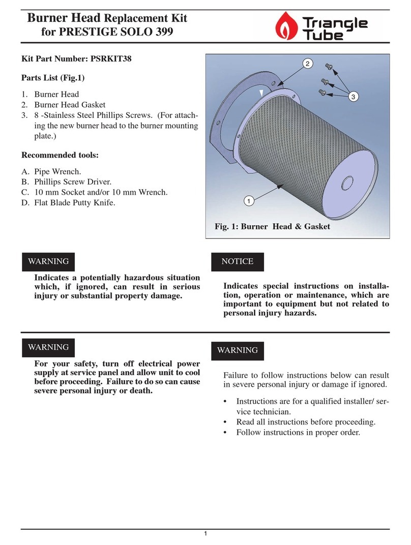
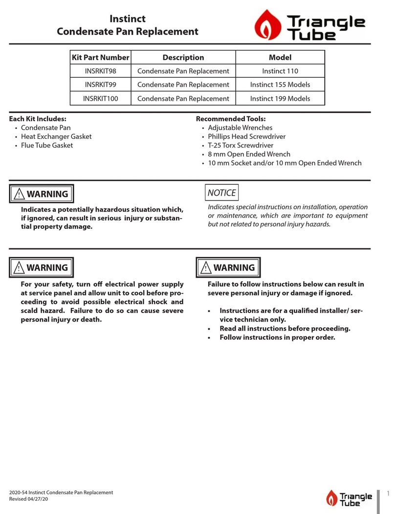
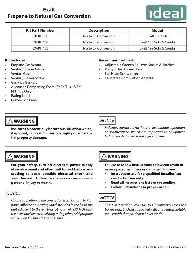
TriangleTube EXRKIT131 Manual

TriangleTube

TriangleTube EXRKIT131 Manual

TriangleTube INSRKIT98 User manual

TriangleTube

TriangleTube INSRKIT98 User manual

TriangleTube PSRKIT38 User manual

TriangleTube

TriangleTube PSRKIT38 User manual

Popular Burner manuals by other brands

Giersch M10-AE Technical information and installation instructions

Giersch

Giersch M10-AE Technical information and installation instructions

Unigas HTP90A Installation, user's, and maintenance guide

Unigas

Unigas HTP90A Installation, user's, and maintenance guide

Beckett AF instruction manual

Beckett

Beckett AF instruction manual

Outland Firebowl 863 Series owner's manual

Outland Firebowl

Outland Firebowl 863 Series owner's manual

Carlisle Machine Works Welder instruction sheet

Carlisle Machine Works

Carlisle Machine Works Welder instruction sheet

Bentone B 30 A Installation and maintenance  instruction

Bentone

Bentone B 30 A Installation and maintenance instruction

Riello RLS 810/E FGR Installation, use and maintenance instructions

Riello

Riello RLS 810/E FGR Installation, use and maintenance instructions

AOG IRB-18 instructions

AOG

AOG IRB-18 instructions

baltur BTL 14P instruction manual

baltur

baltur BTL 14P instruction manual

Honeywell Q349A Series instruction sheet

Honeywell

Honeywell Q349A Series instruction sheet

Erato GP20+ instruction manual

Erato

Erato GP20+ instruction manual

elco P2.190 L-Z/LMO operating instructions

elco

elco P2.190 L-Z/LMO operating instructions

Riello 3898350 Installation, use and maintenance instructions

Riello

Riello 3898350 Installation, use and maintenance instructions

Unigas IDEA NG280 Instructions for installation, use and maintenance manual

Unigas

Unigas IDEA NG280 Instructions for installation, use and maintenance manual

MUT FIREPOT Series Technical data

MUT

MUT FIREPOT Series Technical data

BENTOFLEX ST120KA Installation and maintenance  instruction

BENTOFLEX

BENTOFLEX ST120KA Installation and maintenance instruction

Riello RLS Series Installation, use and maintenance instructions

Riello

Riello RLS Series Installation, use and maintenance instructions

Riello G3BF 490T53 Installation, use & maintenance manual

Riello

Riello G3BF 490T53 Installation, use & maintenance manual

manuals.online logo
manuals.online logoBrands
  • About & Mission
  • Contact us
  • Privacy Policy
  • Terms and Conditions

Copyright 2025 Manuals.Online. All Rights Reserved.