manuals.online logo
Brands
  1. Home
  2. •
  3. Brands
  4. •
  5. TriangleTube
  6. •
  7. Burner
  8. •
  9. TriangleTube INSRKIT98 User manual

TriangleTube INSRKIT98 User manual

Instinct
Condensate Pan Replacement
1
WARNING
!
Indicates a potentially hazardous situation which,
if ignored, can result in serious injury or substan-
tial property damage.
NOTICE
Indicates special instructions on installation, operation
or maintenance, which are important to equipment
but not related to personal injury hazards.
WARNING
!
For your safety, turn off electrical power supply
at service panel and allow unit to cool before pro-
ceeding to avoid possible electrical shock and
scald hazard. Failure to do so can cause severe
personal injury or death.
WARNING
!
Failure to follow instructions below can result in
severe personal injury or damage if ignored.
• Instructions are for a qualified installer/ ser-
vice technician only.
• Read all instructions before proceeding.
• Follow instructions in proper order.
Kit Part Number Description Model
INSRKIT98 Condensate Pan Replacement Instinct 110
INSRKIT99 Condensate Pan Replacement Instinct 155 Models
INSRKIT100 Condensate Pan Replacement Instinct 199 Models
Each Kit Includes:
• Condensate Pan
• Heat Exchanger Gasket
• Flue Tube Gasket
Recommended Tools:
• Adjustable Wrenches
• Phillips Head Screwdriver
• T-25 Torx Screwdriver
• 8 mm Open Ended Wrench
• 10 mm Socket and/or 10 mm Open Ended Wrench
2020-54 Instinct Condensate Pan Replacement
Revised 04/27/20
Instinct
Condensate Pan Replacement
2
1. Preliminary Instructions
1. Verify that the replacement kit is correct for the
model of boiler. See table on page 1.
2. Carefully open and unpack the PARTS BOX from its
shipping carton.
3. Carefully remove and check for any damage.
NOTICE
Installing damaged components will cause malfunction of
the boiler. Contact Triangle Tube right away if the repair kit
is damaged in any way.
4. Turn o the electrical power supply to the boiler.
5. Close the manual gas shut o valve to the unit.
2. Drain Boiler
1. Make sure the power to the unit “OFF” and allow
unit to cool.
2. Close all isolation valves on the system piping to
the boiler. Close the ll valve line to the system.
3. Connect a garden hose to the boiler drain.
4. Direct the hose to a suitable place of drainage. En-
sure boiler drain connection is between the boiler
and the closed isolation valve.
5. Open the drain valve and begin draining the boiler.
NOTICE
To assist in the draining of the boiler, remove the air vent at
the top of the unit or manually lift open the pressure relief
valve.
WARNING
!
Water from the boiler drain connection may be ex-
tremely hot. To avoid personal injury, death or sub-
stantial property damage:
- Tighten all drain hose connections to avoid leakage.
- Direct hot water away from all persons.
3. Removal of the Burner Assembly
1. Remove front jacket panel of the boiler by loos-
ening the one phillips screw on the bottom of the
front jacket. Do not discard this screw as it will be
reused.
2. Disconnect all the wires from the gas valve, blower
and igniter.
NOTICE
Mark the proper location of all wires before removing them.
3. Remove the silicone tube from the air inlet elbow.
Keep the silicone tube attached to the gas valve.
WARNING
!
Inspect the silicone tube to ensure it is not damaged.
Contact Triangle Tube right away if the tube is dam-
aged in any way.
4. Remove the air inlet elbow from the venturi.
5. Unscrew the nut on both sides of the gas valve. Do
not discard the gaskets as they will be reused.
Air Inlet
Elbow
Blower
Gas Valve
Igniter
2 in 1 Insulation
Venturi Inlet Pipe
Burner
Fig. 1: Instinct 110 Burner Assembly
Instinct
Condensate Pan Replacement
3
Air Inlet Elbow
Blower
Gas Valve
Igniter
2 in 1 Insulation
Venturi
Inlet Pipe
Burner
Fig. 2: Instinct 155 Burner Assembly
Air Inlet
Elbow
Blower
Gas Valve
Igniter
2 in 1 Insulation
Venturi
Inlet Pipe
Burner
Fig. 3: Instinct 199 Burner Assembly
6. Remove the two screws on securing the gas valve
bracket to the heat exchanger mounting plate. Do
not discard these screws as they will be reused. Re-
move the gas valve and bracket from the boiler.
WARNING
!
Inspect the gas valve to ensure they are not damaged.
Contact Triangle Tube right away if damaged in any
way.
Fig. 4: Blower Bolt Holes
7. The two hard to reach bolt holes under the blower
housing are slotted, see Fig. 4. Fully remove the two
other 8mm bolts securing the blower to the burner
mounting plate. Unscrew the other two bolts only
as much as is needed to remove the blower/venturi
assembly.
8. Slide the blower/Venturi forward to disengage the
rear bolts and remove the blower/venturi from the
boiler. Do NOT discard the blower gaskets. Do NOT
discard the bolts as they will be reused.
WARNING
!
Inspect the blower and venturi to ensure they are not
damaged. Contact Triangle Tube right away if either is
damaged in any way.
9. Remove the two Phillips head screws securing the
burning mounting plate to the rear jacket panel.
These screws are for shipping protection and can
be discarded.
10. Remove the 10 mm burner plate mounting nuts
mounting the plate to the heat exchanger. Do not
discard the nuts as they will be reused.
11. Lift the combustion chamber insulation and burn-
er mounting plate together. Remove the insula-
tion/burner straight up from the heat exchanger
body to ensure the igniter and burner head are not
damaged.
Instinct
Condensate Pan Replacement
4
Fig. 5: Instinct 110
Fig. 6: Instinct 155 Solo
Fig. 7: Instinct 199 Solo
Fig. 8: Instinct 155 Combi
Instinct
Condensate Pan Replacement
5
Fig. 9: Instinct 199 Combi
4a. Removal of Condensate Trap (Solo Models)
Fig. 10: Condensate Trap
1. External to the boiler cabinet, pinch and remove
the retention clip securing the condensate trap.
See Fig. 10.
2. Unscrew the retaining nut securing the conden-
sate trap and pull down from nipple.
3. Pull the retaining nut and seals o the drain nipple.
Do not discard the seals as they will be reused.
4b. Removal of Condensate Trap (Combi Models)
1. Remove the access panel on the bottom of the
boiler cabinet. Do not discard the three screws as
they will be reused.
2. Unscrew the retaining nut securing the conden-
sate trap.
3. Pull the condensate trap down to disengage it from
the heat exchanger.
4. Pull the retaining nut and seals o the drain nipple.
Do not discard the seals as they will be reused.
5. Removal of Flue Tube
1. Disconnect the molex plug connected to the ue
temperature sensor in the ue tube.
2. Remove the ue temperature sensor by pulling it
straight out of the ue tube. Inspect the ue sensor
for any damage.
3. Use a at head screw driver to loosen the banding
clamp located on the ue vent outlet adapter
4. Unscrew the four screws securing the ue vent
adapter to the top jacket panel. Do not discard
these screws as they will be reused.
5. Disconnect the vent piping from the ue vent
adapter.
6. Twist and lift the vent adapter up to disengage
from the ue tube and remove.
7. Twist and lift the ue tube up and out of the ue
tube seat.
8. Remove the ue tube out of the boiler by pulling
it straight up out the vent adapter hole in the top
jacket panel.
6. Disconnect Boiler Piping
1. Loosen the two nuts securing the boiler piping to
the heat exchanger. See Fig. 5 - Fig. 9.
2. Do not discard the gaskets as they will be reused.
Instinct
Condensate Pan Replacement
6
7. Removal of Heat Exchanger
1. Unscrew the two T25 Torx screws securing the heat
exchanger to the back jacket panel. Do not discard
these screws as they will be reused. See Fig. 11.
Fig. 11: Heat Exchanger Bracket Screws
2. Lift the heat exchanger up to disengage from the
brackets on the back jacket panel. Once disen-
gaged, remove heat exchanger from the boiler.
8. Remove Condensate Pan
1. Loosen and remove all nuts securing the conden-
sate pan to the bottom of the heat exchanger. Do
not discard the nuts as they will be reused.
2. Remove the condensate pan from the heat ex-
changer. Mark the orientation of the condensate
pan on the heat exchanger.
NOTICE
If the condensate pan is install in the incorrect orientation,
the nal t up of all the connections will not be possible and
it will be necessary to remove the pan and correct the orien-
tation.
3. Remove and discard the gaskets in the top open-
ing and in the ue tube seat.
9. Install New Condensate Pan
1. Seat the new ue tube gasket in the ue tube seat.
2. Seat the new condensate pan gasket in the recess
as shown in Fig. 12 with the side with less ribs fac-
ing upward.
3. Install the condensate pan onto the bottom of the
heat exchanger in the same orientation as the pre-
vious pan.
Fig. 12: Condensate Pan Gasket
WARNING
!
Ensure the gasket is in place before reassembly. Fail-
ure to do so can result serious injury or substantial
property damage.
4. Hand tighten all nuts on the condensate pan. Once
all of the nuts are hand tight, fully torque all nuts in
a star pattern.
10. Installation of Heat Exchanger
1. Lift the heat exchanger with the new pan and care-
fully engage both brackets in the rear jacket panel.
Gently tug the boiler to ensure both brackets are
engaged.
2. Tighten both T25 torx screw in the top bracket. See
Fig. 11.
11. Attach Boiler Piping
1. Reinstall the gaskets into the boiler nuts.
WARNING
!
Ensure the gasket is in place before reassembly. Fail-
ure to do so can result serious injury or substantial
property damage.
2. Tighten both boiler piping nuts.
12. Install Flue Tube
1. Install the ue tube through the hole in the top
Instinct
Condensate Pan Replacement
7
jacket panel.
2. Push and twist the ue tube into the ue tube seat.
Ensure the rubber seal is in place in the ue tube
seat. Orient the ue tube so that the ue sensor is
facing forward.
3. Ensure the rubber seal is in place in the top of the
ue tube. Reinstall the vent outlet adapter, pushing
it down rmly to secure it to the ue tube.
WARNING
!
Ensure the gasket is in place before reassembly. Fail-
ure to do so can result death, serious injury or sub-
stantial property damage.
4. Reinstall the four screws to secure the vent adapter.
WARNING
!
Ensure the screws are in firmly installed prior to start-
ing the boiler. Failure to do so can result death, seri-
ous injury or substantial property damage.
5. Reconnect the vent piping to the vent outlet
adapter. Tighten the banding clamp with a at-
head screwdriver to secure the vent piping to the
adapter.
WARNING
!
Ensure the venting is tight and secure prior to start up.
Failure to do so can result death, serious injury or sub-
stantial property damage.
6. Reinstall the ue temperature sensor by pushing it
into the rubber boot.
7. Plug in the molex plug into the ue sensor.
11a. Installation of Condensate Trap (Combi Models)
1. Install the retaining nut and both seals onto the
drain nipple. See Fig. 10.
2. Push the condensate trap onto the condensate
nipple as far as it will go.
3. Tighten the retaining nut to the condensate trap to
secure the condensate trap.
4. Pull the condensate drain hose out the bottom of
the boiler.
5. Install the access panel and tighten the three Phil-
lips screw.
11b. Installation of Condensate Trap (Solo Models)
1. Push the retaining nut and both seals onto the
drain nipple. See Fig. 10.
2. Push the condensate trap onto the drain nipple as
far as it will go.
3. Tighten the retaining nut to the condensate trap to
secure the condensate trap.
4. Pinch and install the retention clip to secure the
condensate trap.
12. Install Burner Assembly
1. Align the burner/combustion chamber insulation
with the gas valve facing the front of the boiler. See
Fig. 1, Fig. 2, Fig. 3.
2. Align the bolt holes in the insulation and burner
mounting plate. Carefully install the assembly into
the heat exchanger, pushing the heat exchanger
studs through the bolt holes.
WARNING
!
Ensure the burner/gas valve/igniter are not damaged.
Contact Triangle Tube right away if any item is dam-
aged in any way.
3. Reinstall the burner plate nuts. Make all nuts hand
tight. Once all nuts are nger tight, torque all nuts
to 44-53 in-lbs in a star pattern.
4. Place the blower gasket in place onto the burner
mounting plate.
5. Place the blower/venturi assembly onto the mount-
ing plate by sliding the two slotted holes onto the
two partially installed bolts. Tighten all four 8mm
Instinct
Condensate Pan Replacement
8
bolts to secure the blower in place.
WARNING
!
Ensure the gasket is in place before reassembly. Fail-
ure to do so can result in death, serious injury or sub-
stantial property damage.
6. Install the gaskets and tighten the gas piping nuts
to the gas valve.
WARNING
!
Ensure the gasket is in place before reassembly. Fail-
ure to do so can result in death, serious injury or sub-
stantial property damage.
7. Push the air inlet elbow into the venturi and vent
adapter.
8. Reinstall the silicon tube onto the brass tting on
the air inlet elbow.
WARNING
!
Ensure the silicon tube is secure on both ends. Failure
to do so may cause the boiler to malfunction and can
result in death, serious injury or substantial property
damage.
9. Reconnect all wires to the igniter, gas valve, and
blower.
13. Return to Service
1. If previously removed, reinstall the air vent at the
top of the boiler.
2. Open all isolation valves to rell the boiler.
3. Carefully inspect all joints for water leaks. Tighten
any loose connections.
4. Turn on gas supply to the inlet of the unit at the
main manual shuto valve to the unit. Check and
test all gas connections for leaks. Repair leaks if
found.
WARNING
!
Do not check for gas leaks with an open flame. Use a
bubble test. Failure to check for gas leaks can cause
severe personal injury, death or substantial property
damage.
5. Turn power to the unit “ON”. Run a combustion
analysis test prior to returning to service.
14. Combustion Test and Adjustments
NOTICE
The installer MUST perform a complete combustion check
to ensure the following combustion levels are met at high
and low input ring rates and the burner is operating at op-
timum conditions.
Table 1: Recommended Combustion Settings
NG
110, 155
NG
199
Propane
High Fire
CO2Range 9.0 to
10.5%
8.5 to
10.5%
10.4 to
11.0%
O2Range 4.85 to
2.15 %
5.75 to
2.15 %
5.1 to
4.2 %
CO Max 150 ppm 200 ppm
Low Fire
CO2Range 9.0 to
10.0 %
8.5 to
10.0 %
10.4 to
11.0 %
Lower than or equal to High Fire
CO2level
O2Range 4.85 to
3.0 %
5.75 to
3.0 %
5.1 to
4.2 %
Higher than or equal to High Fire
CO2level
CO Max 10 ppm
WARNING
!
The combustion testing and adjustments must be per-
formed by a qualified installer, service agency or the
gas supplier. All combustion measurements must be
performed with calibrated equipment to ensure prop-
er readings and accuracy.
Instinct
Condensate Pan Replacement
9
WARNING
!
Failure to perform a complete combustion test at both
high and low input rates may result in incomplete
combustion and the production of carbon monoxide,
which can cause severe personal injury, death or sub-
stantial property damage.
1. Touch simultaneously on the up and down soft
keys (as high lighted by the wrench icon) for 3 sec-
onds to access the functions for the installer. See
Fig. 13.
2. Enter the installer access code “054” by using the
LEFT and RIGHT buttons to select a digit and the UP
and DOWN buttons to change the digit. Press the
center button to enter the access code.
Fig. 13: CTRLMax Navigation Control
Fig. 14: Controls display
3. Press the RIGHT button to highlight the Manual
Operation icon then press the OK button.
4. Press the center button while the FAN icon is high-
lighted to manually re the burner and power the
CH circulator. See Fig. 14
NOTICE
An adequate CH load must be present to dissipate the heat
generated during the combustion test. If an adequate CH
load is not available, an indirect water heater can be used to
dissipate the heat by creating a DHW call which will enable
the DHW circulator.
5. Press the RIGHT button to adjust the ring rate to
100% (high re). Hold down the RIGHT button to
rapidly increase the ring rate.
6. If the combustion levels during high re are outside
the recommended combustion settings, adjust the
THROTTLE SCREW using a at-blade screwdriver as
follows:
Counter-clockwise adjustment of the THROTTLE
SCREW at High Fire (100% firing rate):
Increase CO2 & Decrease O2
Clockwise adjustment of the THROTTLE SCREW at
High Fire (100% firing rate):
Decrease CO2 & Increase O2
7. Once the combustion level is set at high re, manu-
ally place the boiler into low re mode by pressing
the LEFT button to adjust ring rate down to 0%
(low re).
8. If the combustion level (O2 or CO2) during low re
is not within +/-0.2 of the combustion level mea-
sured at high re, shut down the boiler and contact
Triangle Tube Tech Support at 856-228-3584, ext.
500

This manual suits for next models

2

Other TriangleTube Burner manuals

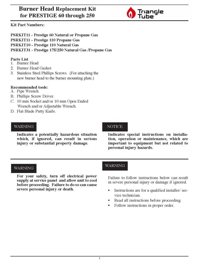
TriangleTube PSRKIT11 User manual

TriangleTube

TriangleTube PSRKIT11 User manual

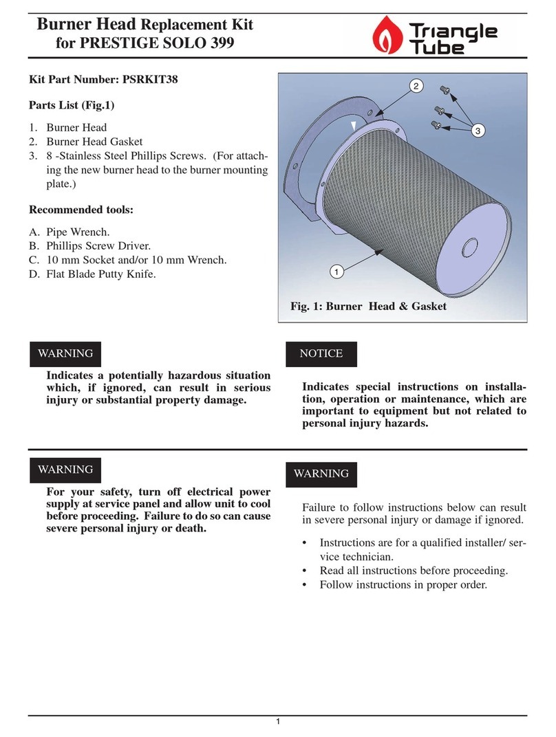
TriangleTube PSRKIT38 User manual

TriangleTube

TriangleTube PSRKIT38 User manual

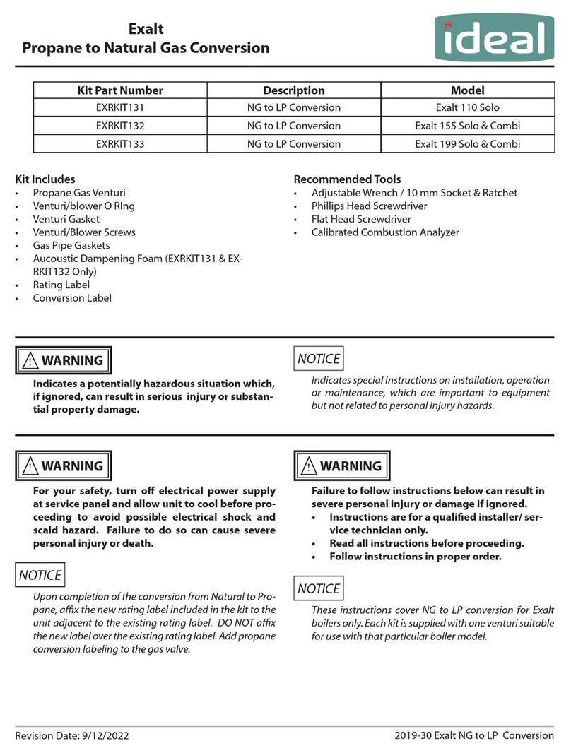
TriangleTube EXRKIT131 Manual

TriangleTube

TriangleTube EXRKIT131 Manual

Popular Burner manuals by other brands

Berner BAWH1 manual

Berner

Berner BAWH1 manual

Riello RS5F Installation, use and maintenance instructions

Riello

Riello RS5F Installation, use and maintenance instructions

Ecoflam Multiflam 300.1 manual

Ecoflam

Ecoflam Multiflam 300.1 manual

Duraflame illuma 61000 owner's manual

Duraflame

Duraflame illuma 61000 owner's manual

Riello DB 4 LSM C13 Installation, use and maintenance instructions

Riello

Riello DB 4 LSM C13 Installation, use and maintenance instructions

Dabos Prity Instructions for installation and operation

Dabos

Dabos Prity Instructions for installation and operation

Primus Lite XL Piezo manual

Primus

Primus Lite XL Piezo manual

Solus Halo Installation & operation manual

Solus

Solus Halo Installation & operation manual

Riello 40 GS20 TL Installation, use and maintenance instructions

Riello

Riello 40 GS20 TL Installation, use and maintenance instructions

Ecoflam MAIOR P 15 AB manual

Ecoflam

Ecoflam MAIOR P 15 AB manual

Riello RLS 68/E MX Installation, use and maintenance instructions

Riello

Riello RLS 68/E MX Installation, use and maintenance instructions

Riello RS 70 Installation, use and maintenance instructions

Riello

Riello RS 70 Installation, use and maintenance instructions

Adams SPEEDFLAME operating manual

Adams

Adams SPEEDFLAME operating manual

Riello RS BLU Series Installation, use and maintenance instructions

Riello

Riello RS BLU Series Installation, use and maintenance instructions

Riello RL 250 TL Installation, use and maintenance instructions

Riello

Riello RL 250 TL Installation, use and maintenance instructions

Pit Boss PB5BGD1 manual

Pit Boss

Pit Boss PB5BGD1 manual

Hotsy 1800 Series Service manual

Hotsy

Hotsy 1800 Series Service manual

Weishaupt WL40/1-A Z-1LN-A Installation and operating instruction

Weishaupt

Weishaupt WL40/1-A Z-1LN-A Installation and operating instruction

manuals.online logo
manuals.online logoBrands
  • About & Mission
  • Contact us
  • Privacy Policy
  • Terms and Conditions

Copyright 2025 Manuals.Online. All Rights Reserved.