TriangleTube INSRKIT53 Use and care manual

Instinct
Display Module Replacement
1
WARNING
!
Indicates a potentially hazardous situation which,
if ignored, can result in serious injury or substan-
tial property damage.
NOTICE
Indicates special instructions on installation, operation
or maintenance, which are important to equipment
but not related to personal injury hazards.
WARNING
!
For your safety, turn off electrical power supply
at service panel and allow unit to cool before pro-
ceeding to avoid possible electrical shock and
scald hazard. Failure to do so can cause severe
personal injury or death.
WARNING
!
Failure to follow instructions below can result in
severe personal injury or damage if ignored.
• Instructions are for a qualified installer/ ser-
vice technician only.
• Read all instructions before proceeding.
• Follow instructions in proper order.
Kit Part Number Description Model
INSRKIT53 Display Module Replacement Instinct
Each Kit Includes:
• Display Module with cover
Recommended Tools:
• Adjustable Wrenches
• Phillips Head Screwdriver
• Flat Head Screwdriver
2019-45 Instinct Display Module Replacement
Revised 10/23/2109

Instinct
Display Module Replacement
2
1. Preliminary Instructions
1. Verify that the replacement kit is correct for the
model of boiler. See table on page 1.
2. Carefully open and unpack the PARTS BOX from its
shipping carton.
3. Carefully remove and check for any damage.
NOTICE
Installing a damaged equipment will cause malfunction
of the boiler. Contact Triangle Tube right away if the
display module is damaged in any way.
4. Close the manual gas shut o valve to the unit.
2. Save Settings
NOTICE
Prior to replacing the control module and/or display module,
it is important to access and document the boiler’s settings.
This will ensure any settings revised from factory defaults are
transferred to the new module(s). Use Table 1 to record the
existing settings. Do not revise any settings when recording
settings.
1. To access the Installer screen, touching simultane-
ously the up and down soft keys for 3 seconds as
shown in Fig. 1.
Fig. 1: Installer Button
2. Enter the installer access code “054” by using the
LEFT and RIGHT buttons to select a digit and the
UP and DOWN buttons to change the digit. Press
the OK button to enter the access code.
Fig. 2: Installer Access Code
3. Press the OK button while the CH & DHW Settings
icon is highlighted.
Fig. 3: CH & DHW Settings
4. Press the OK button while the CH Settings icon is
highlighted.
Fig. 4: CH Settings
5. Press the UP and DOWN buttons to scroll thru the
various settings.
Fig. 5: Heating Settings

Instinct
Display Module Replacement
3
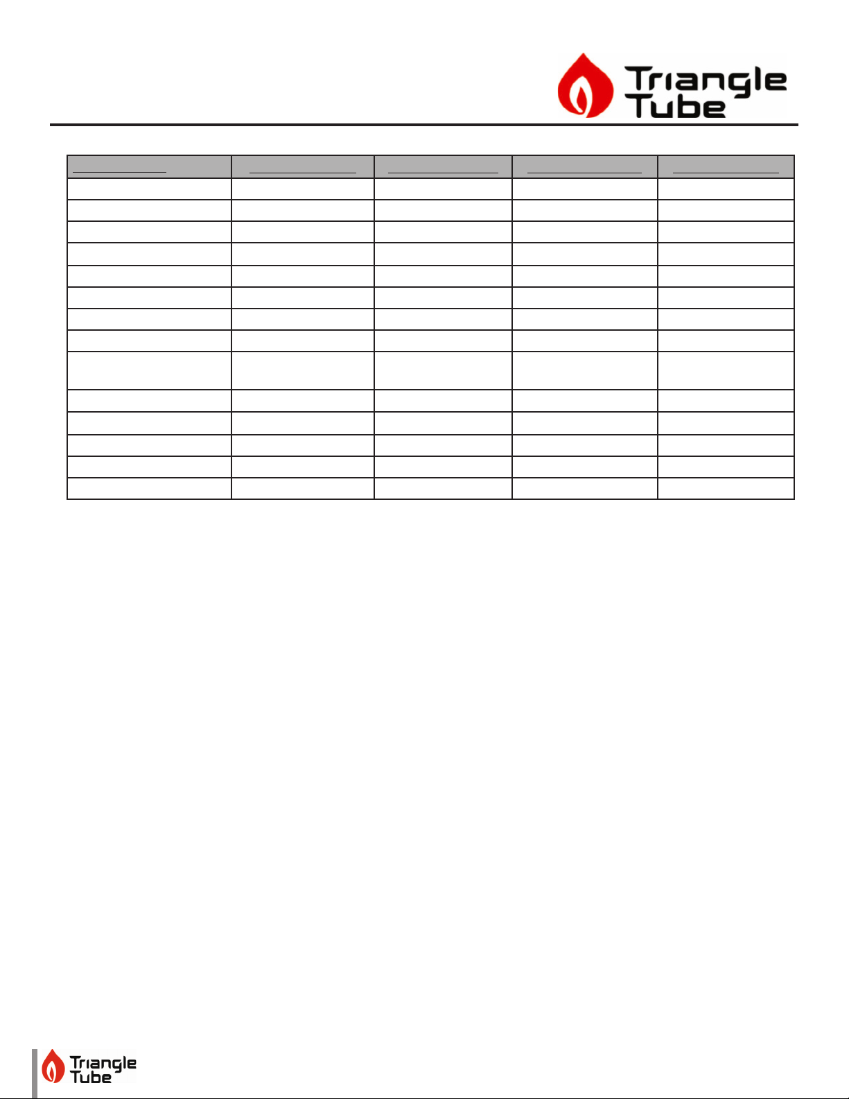
6. Record all CH Settings in Table 1. Once completed,
press the RIGHT button to highlight the Previous
Screen icon, then press the OK button.
7. Press the RIGHT button to highlight the DHW Set-
tings icon then press the OK button.
Fig. 6: DHW Settings
8. Press the UP and DOWN buttons to scroll thru the
various settings and record all DHW Settings in Ta-
ble 1. Once completed, press the RIGHT button to
highlight the Previous Screen icon, then press the
OK button.
Fig. 7: DHW Settings
9. Press the DOWN button to highlight the Boiler Set-
tings icon if present icon, then press the OK button.
10. Press the UP and DOWN buttons to scroll through
the various settings and record all Boiler Settings
in Table 1. Once completed, press the RIGHT but-
ton to highlight the Previous Screen icon, then
press the OK button.
NOTICE
Perform the following steps if the Instinct is part of a Cascade
System or the System Temperature Sensor is being used on a
single HeatMaster.
11. Press the RIGHT then DOWN buttons to highlight
the Previous Screen icon, then press the OK button.
12. Press the RIGHT then DOWN buttons to highlight
the Cascade icon, then press the OK button.
13. Press the RIGHT button to highlight the Cascade
Settings icon, then press the OK button.
14. Press the UP and DOWN buttons to scroll thru the
various settings, and record all Cascade Settings in
Table 1.
3. Replace Display Module
1. Turn the electrical power“OFF”.
NOTICE
The display module comes preinstalled in the front red dis-
play enclosure as shown in Fig. 8.
Fig. 8: Display Module
2. Remove the front jacket by removing the screw on
the bottom. Lift and remove the front cover. Do not
discard this screws as they will be reused.
3. Pull the retaining clip on top of the enclosure and
pull the front cover o.
4. Disconnect the yellow cables by squeezing the clip
on the back of the plug in and pulling rmly out
from the back of the display module. Use care not
to damage the plug.
5. Remove the rubber grommet holdind the yellow
cables from the old display ensloure.
6. Install the rubber grommet with the yellow cables
onto one of the tabs in the bottom of the new dis-
play ensloure.

Instinct
Display Module Replacement
4
7. Reconnect the yellow cables by pushing the plug
into the terminal. The clip on the back of the plug
will lock the plug into place. Use care not to dam-
age the cable or display module.
8. Close the front cover onto the back cover by insert-
ing the two tabs on the bottom of the front cover
into the appriopriate holes in the back cover and
close, engaging the tab in the top. Give the cover a
light tug to make sure the top retaining clip is tight.
4. Programming new Display Board
1. Follow the instructions in step 2 to gain access to
the installer menu.
2. Go to boiler settings and click appliance setting, as
seen in Fig. 9 and Fig. 10.
Fig. 9: Installer Menu
Fig. 10: Appliance setting
3. The required code is written on the data plate lo-
cated at the side of the boiler. Use the code for the
gas type, either Natural Gas or Propane.
4. Increase/decrease the value (from 0 to 9, then A to
Z) using the UP or DOWN keys to, then change po-
sition with the LEFT or RIGHT keys.
5. Follow the instructions on the screen to enter the
appliance code for your boiler.
6. The boiler will now be factory set for that particular
model. Return to step 2 and enter settings record-
ed in Table 1 back into the controls to return the
boiler to the customized settings of the old control.
7. Return to step 2 and enter settings recorded in Ta-
ble 1 back into the controls.

Instinct
Display Module Replacement
5
Table 1: Controls Settings
HEATINGSETTING FACTORYDEFAULT MINIMUMSETTING MAXIMUMSETTING EXISTINGSETTING
Heating Operation Enabled
Demand Type Thermostat & Outd.
Curve
Absolute Max CH Setpoint 185°F [85°C] 68°F [20°C] 188°F [87°C]
CH1 Maximum Setpoint 180°F [82°C] 68°F [20°C] 188°F [87°C]
CH1 Minimum Setpoint 80°F [27°C] 60°F [15°C] 188°F [87°C]
Outdoor Curve Coldest Day 10°F [-12°C] -30°F [-34°C] 50°F [10°C]
Outdoor Curve Warmest Day 64°F [18°C] 60°F [15°C] 78°F [25°C]
CH2 Circuit Enabled
CH2 Maximum Setpoint 140°F [60°C] 68°F [20°C] 194°F [90°C]
CH2 Minimum Setpoint 80°F [27°C] 60°F [15°C] 190°F [88°C]
Warm Weather Shutdown O O 78°F [25°C]
Circulation Pump
Permanent
Disabled
CH Post Pump Time 5 Minutes O 20 Minutes
Freeze Protection Enabled
Frost Protection Setpoint -22°F [-30°C] -22°F [-30°C] 50°F [10°C]
Parallel Shift Value 0°F [0°C] 0°F [0°C] 144°F [80°C]
CH Call Blocking 2 Minutes 0 Minutes 30 Minutes
DOMESTICSETTING SOLO
FACTORY
DEFAULT
COMBI
FACTORY
DEFAULT
MINIMUM
SETTING
MAXIMUM
SETTING
EXISTING
SETTING
DHW Operation Enabled Enabled
Demand Type Thermostat N/A
DHW Boiler Setpoint 168°F [76°C] 168°F [76°C] 96°F [35°C] 188°F [87°C]
DHW Setpoint 140°F [60°C] 140°F [60°C] 68°F [20°C] 168F [75°C]
DHW Warmstart Setpoint N/A 125°F [52°C] 86°F [30°C] 140°F [60°C]
DHW Warmstart Hysteresis N/A 30°F [17K] 9K 36K
DHW On Dierential 6°F [3°C] N/A 4°F [2°C] 18°F [10°C]
DHW Storage Adder 27°F [15°C] 18°F [10°C] 10°F [5°C] 54°F [30°C]
DHW Post Pump Time 2 Minutes 2 Minutes O 30 Minutes
DHW Priority Timeout O O O 120 Minutes
DHW Priority Enabled Enabled
DHW Call Blocking 1 Minute 1 Minute 0 Minute 30 Minutes
DHW to CH Call Blocking 1 Minute 1 Minute 0 Minute 30 Minutes
Antilegionella Function Disabled Enabled

Instinct
Display Module Replacement
6
Table 1 Cont:
BOILERSETTING FACTORYDEFAULT MINIMUMSETTING MAXIMUMSETTING EXISTINGSETTING
Lockout Temp. 210°F [99°C]
Modbus Address 0=BCST 0=BCST 247
Flex. Relay 1(CH) CH1
Flex. Relay 2(DHW) DHW
Flex. Relay 3(P3) CH1/CH2/DHW
Flex. Relay 4(ERR) ERROR
Flex. Relay 5(Flame) FLAME
Flex. Relay 6(P4) CH2
Error Relay On Lockout, Blocking
andWarning
Pump PWM Minimum 30% 1% 100%
Ignition Level Varies by model
Mix Zone High Limit 114°F [45°C] 68°F [20°C] 176°F [80°C]
Appliance Setting Varies by model
Altitude Setting 0 ft 0 ft 20,000 ft
Table of contents