Triarchy Technologies VSG6G1 User manual
Page 1 of 33
Triarchy®VSG6G1/VSG2G1/TSG4G1
USB Vector RF Signal Generator
Operating Manual
CW signal Analog modulation GMSK modulation 64 QAM NB RF noise generator
Pulse modulation Frequency sweeping Hopping with data Mod GSM signal arbitrary signal generator

Page 2 of 33
USB Vector RF Spectrum Analyzer Operating Manual
Copyright Notice
Copyright © 2015 Triarchy Technologies, Corp. All rights reserved.
Initial Version August 2015
Documentation version 1.0
No part of this publication may be reproduced, transmitted, transcribed, stored in a retrieval system, or translated into
any language or computer language, in any form or by any means, electronic, mechanical, magnetic, optical, chemical,
manual, or otherwise, without the prior written permission of Triarchy Technologies, Corp.
Technical Support
For technical support, please call 1-604-637-2167, send email to info@triachytech.com, or visit our website at
http://www.triarchytech.com

Page 3 of 33
Contents
1 Introduction 4
1.1 Product Package Overview 4
1.2 USB Device Overview 4
1.3 TSG PC Application Overview 5
1.4 Electrical Requirements 7
2 Getting Started 9
2.1 Install PC Application 9
2.2 Uninstall PC Application 11
2.3 First Working Example 11
2.4 TSG Utility keys setting 11
3 Operations 13
3.1 CW Signal Output 13
3.2 Pulse modulation Signal Output 14
3.3 AM Signal Output 14
3.4 FM Signal Output 15
3.5 Frequency shift 16
3.6 Analog Modulation with I&Q raw data file 16
3.7 GMSK signal Output 17
3.8 FSK signal Output 18
3.9 Digital Modulation with I&Q Engine 18
3.10 QPSK Signal output 19
3.11 8PSK Signal output 20
3.12 16QAM Signal output 20
3.13 Phase Modulation with I&Q Engine 21
3.14 Frequency Sweeping without Pulse Modulation 22
3.15 Frequency Sweeping with Pulse Modulation 23
3.16 Frequency hopping without Pulse Modulation 23
3.17 Frequency Hopping with Pulse Modulation 24
3.18 S11/S21 measurement 25
3.19 Example for GSM signal output 26
3.20 Pulse modulation signal output 27
3.21 SIN/Triangle/Spiral waveform signal output 27
3.22 Clock selection 27
3.23 I&Q Selection 28
3.24 Hardcopy Operation 28
4 I&Q Engine 28
4.1 I&Q Engine principle 28
4.2 I&Q file configuration 31

Page 4 of 33
1 Introduction
VSG6G1/VSG2G1/TSG4G1 is a USB RF signal generator that plugs on PC and works using PC or tablet application.
For VSG6G1: the RF frequency range is from 1MHz to 6.2GHz, amplitude output range will be -60dBm~10dBm.
For VSG2G1: the RF frequency range is from 30MHz to 2.2GHz, amplitude output range will be -60dBm~10dBm.
For TSG4G1: frequency range is from 35MHz to 4.4GHz, and amplitude is from -60dBm to 0dBm.
VSG6G1 /VSG2G1/TSG4G1 will be very easy to use. The application's user interface is designed to be just like
the front panel of normal desktop signal generators, allowing signal generator users to easily pick up and use the
application intuitively without a high learning curve. If your PC or tablet support touch screen, the user
experience will be even more realistic to a desktop signal generator.
VSG6G1 have additional functions: such as the generation of modulation signal with I&Q engine and Pulse
modulation so that it can simulate a lot of wireless systems.
1.1 Product Package Overview
VSG6G1/VSG2G1/TSG4G1 product package will be:
1: USB signal generator device (25x25x100mm) one piece
2: mini USB cable one piece
3: SMA to MMCX cable one piece
4: N to SMA adapter one piece
5: 30 dB attenuator one piece
6: CD with PC application program and document one piece
7: 160x110x40mm product case one piece
1.2 USB Device Overview
RF output
N connector (female)
RF signal output
USB connector
Mini-B USB connector
interface with PC
IP
MMCX connector
I port positive Output/Input
IN
MMCX connector
I port negative Output/Input
QP
MMCX connector
Q port positive Output/Input
QP
MMCX connector
Q port negative Output/Input
Clock
MMCX connector
Clock Output/Input
Pulse
MMCX connector
Pulse signal Output
Page 5 of 33
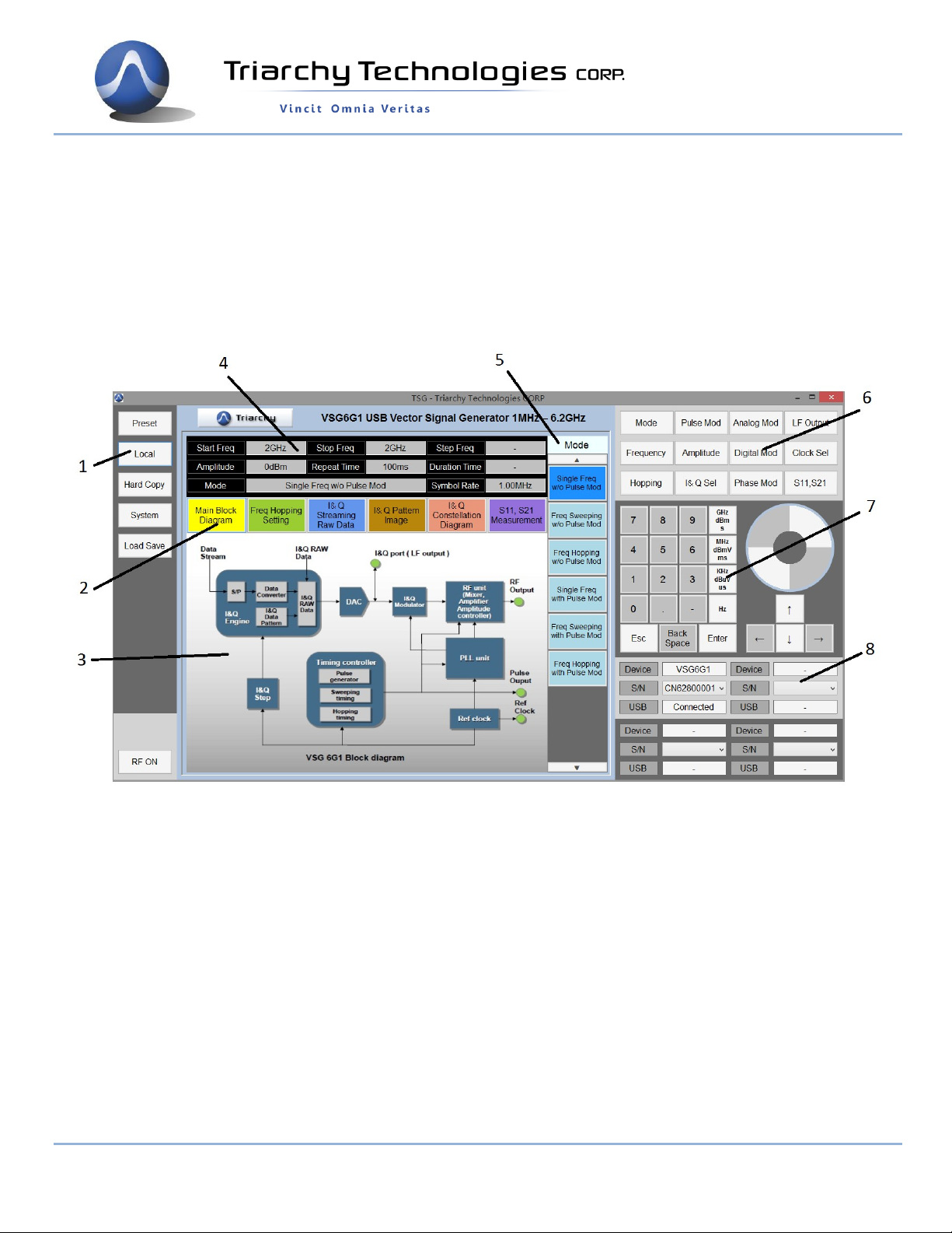
1.3 TSG PC Application Overview
1: utility keys
Allows user to access the system level function. Function detail will be shown on second function keys
2: Message selection keys
Click the Message selection key, the Message display area will change according to selection.
3: Message display area
Message display area shows detailed information about output signal.
Main Block Diagram illustrates how the RF vector signal generator working, how the signal is output.
Freq Hopping setting shows a table of hopping frequency points.
I&Q Streaming Raw Data is waveform of I&Q raw data, it will be same as real waveform signal from I&Q
port.
I&Q pattern image shows I&Q pattern if I&Q raw data is generated based on the I&Q pattern.
I&Q constellation diagram is shown, it will be selected depending on Raw data or I&Q pattern.
S11, S21 Measurement shows the waveform of S11 and S21 test result.
4: Status block
Status block shows the main parameter of output signal: such as frequency, amplitude, repeat time,
duration, symbol rate and working mode.

Page 6 of 33
5: Second functions keys
Second function keys will extend secondary functions relative to the primary function keys and utility
key. It is similar to soft key in most of equipment which is location on side of screen.
6: Function keys
Most of major the equipment settings are done by the Function keys. General setting for signal
generator will be: Select mode: such as frequency selection for single, sweeping and hopping and pulse
modulation selection.
Input frequency: such as setting for signal frequency, frequency sweeping and frequency hopping
Input amplitude: such as level setting, external attenuator selection and setting.
Input timing: for pulse modulation.
Adding I&Q modulation: to setup a lot of different kind of modulation to meet each application
requirements.
7: Digital input keys
Digital input keys will input digital and units for frequency, amplitude and timing. This standalone input
key is similar to desktop equipment
Frist select the digital at second function, frequency, amplitude and timing.
Then operate keypad , navigation keys and Knob to change the input value.
Knob Operation
When the mouser cursor hovers over each of the four buttons on the knob: ++, +, --, - icon will display.
Click and hold on each icon to increase or decrease value:
++ fast increase
+ slowly increase
-- fast decrease
- Slowly decrease
After input digital, it need to input unit to finish all setting.
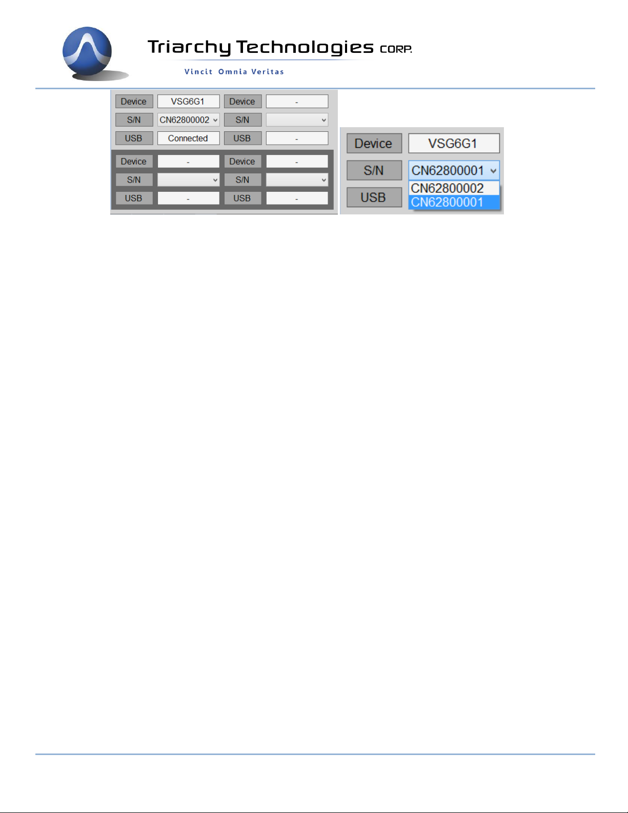
8: USB connection area
When VSG6G1/VSG2G2/TSG4G1 is plugged in the PC, USB connection area will display the product
model name, S/N and connection status. A device is properly connected to and recognized by the
application program when Model number, S/N and connected status are all displayed.
Page 7 of 33
9248 163 Street
Surrey, BC V4N 3C9
604-637-2167
info@triarchytech.com
One PC can connect multiple VSG6G1/VSG2G1/TSG4G1 device. Select S/N item to choose which device
will is used. When multiple TSG application are opened, each TSG can connected to each hardware
device by choice proper the S/N.
1.4 Electrical Requirements
1.41 Specification for Frequency
Frequency range for VSG6G1:
Band 0: 1MHz ~30MHz Band
1: 30MHz ~2200MHz Band 2:
2200MHz ~6200MHz
Frequency range for VSG2G1:
Band 1: 30MHz ~2200MHz
Frequency range for TSG4G1:
Band 1: 35MHz ~4400MHz
Frequency resolution: 1 KHz with PLL setting
Frequency offset: +/-2Hz to +/-1KHz with I&Q Freq Shift +/- setting
* frequency offset can only be setup at single frequency mode without any modulation ( not working at TSG4G1)
Frequency stability: +/-2.5PPM over temperature -20~+60 degree
Frequency aging per year: +/-1PPM
Frequency reference output: 12MHz
Frequency reference input: 10MHz/5dBm
1.4.2 Specification for power
Output level range for VSG6G1 :
Band 0: -21dBm~10dBm
Band 1: -21dBm~10dBm
Band 2: -31dBm~0dBm
Output level range for VSG2G1 :
Band 1: -21dBm~10dBm
Output level range for TSG4G1 :
Band 1: -31dBm~0dBm
Output level resolution: 1dB
Output level error: <3dB
Phase noise:
-90dBc/Hz offset 10 KHz at 1GHz
-105dBc/Hz offset 100 KHz at 1GHz
-120dBc/Hz offset 1MHz at 1GHz

Page 8 of 33
9248 163 Street
Surrey, BC V4N 3C9
604-637-2167
info@triarchytech.com
1.4.3 Specification for Pulse modulation
Pulse repeat time: 400uS to 20s
Pulse duration time: 10us to 5S
Multiple pulse number: 2~250
Multiple pulse delay: 100us~5s (last pulse cannot be overlay with first pulse)
On/off ratio: >90dB
1.4.4 Specification for Frequency sweeping with/ without pulse modulation
Span range: 1 KHz to full span
Scan points range: 2 to 50000
Frequency step range: 1 KHz to 1GHz
Pulse period ( set at Pulse Mod): repeat time 400uS to 20s
Pulse width ( set at Pulse Mod): duration time 10us to 10s
* If it is in “Freq sweeping w/o Pulse mod”, this parameter is no function
1.4.5 Specification for Frequency hopping with/ without pulse modulation
Frequency hopping range: 1MHz to 6.2GHz (30MHz to 2.2GHz for VSG2G1/
35MHz to 4.4GHz for TSG4G1)
Frequency hopping number: 2~4000
hopping times(Pulse period): 2500 hop/s to 0.05 hop/s (or repeat time 400uS to 20s)
Pulse width ( set at Pulse Mod): duration time 10us to 10s
* If it is in “Freq hopping w/o pulse mod”, this parameter is no function
1.4.6 Specification for I&Q unit for analog modulation (not suit for TSG4G1)
FM modulation in Demo key: Modulation frequency range: 1.5Hz to 3.3KHz; Modulation index 20
FM modulation by defined the file, load different file:
Modulation frequency range: 1.5Hz to 33KHz
Modulation index 0.5 to 20
AM modulation in Demo key: Modulation frequency range: 30.7Hz to 66.7KHz; Modulation index 90%
AM modulation by defined the file, load different file:
Modulation frequency range: 1.5Hz to 66.7KHz
Modulation index 10%to90%
PM modulation in Demo key: Modulation frequency range: 30.7Hz to 66.7 KHz;
Modulation index 180 degrees
PM modulation by defined the file, load different file:
Modulation frequency range: 30.7Hz to 66.7KHz
Modulation index 36 degree to 288 degree
*Define the I&Q RAW data file, any kind of analog modulation can be achieved. Such as RF narrow band noise
generator.
1.4.7 Specification for I&Q unit for Digital modulation (not suit for TSG4G1)
MSK modulation in Demo key: Data rate rage: 110b/s to 240Kb/s; Data depth: 400 bit
GMSK modulation in Demo key: Data rate rage: 110b/s to 240Kb/s; Data depth: 400 bit; BT=0.3
FSK modulation in Demo key: Data rate rage: 27.7b/s to 60Kb/s; Data depth: 25 bit
* Define the I&Q data file, study different I&Q pattern, internal I&Q engine will generate the most of digital
modulation; Such as SFSK.
1.4.8 Specification for I&Q unit for phase modulation (not suit for TSG4G1)
QPSK modulation in Demo key: Data rate rage: 2.2kb/s to 4.8Mb/s; Data depth: 4000 bit
8PSK modulation in Demo key: Data rate rage: 3.3kb/s to 7.2Mb/s; Data depth: 4000 bit
Page 9 of 33
9248 163 Street
Surrey, BC V4N 3C9
604-637-2167
info@triarchytech.com
16QAM modulation in Demo key: Data rate rage: 4.4kb/s to 9.6Mb/s; Data depth: 4000 bit
* Define the I&Q data file, study different I&Q pattern, internal I&Q engine will generate the most of digital
modulation; Such as 64QAM.
1.4.9 Specification for I&Q external modulation (not suit for TSG4G1)
Baseband signal bandwidth: 500MHz
I&Q signal level: 1Vpp
I&Q port impedance: 200 ohm
* any kind of modulation will be depended on the input of I&Q signal
1.4.10 Specification for LF output
SIN Waveform in Demo: Waveform pattern length: 72 point.
Frequency range: 15.4Hz to 33.3 KHz
Signal level: 1VPP
Triangle Waveform in Demo: Waveform pattern length: 36 point
Frequency range: 30.8Hz to 66.6 KHz
Signal level: 1VPP
Spiral waveform in Demo: Waveform pattern length: 720 point
Frequency range: 1.5Hz to 3.3 KHz
Signal level 1VPP
Total I&Q raw data length: 4Kb
I&Q points range: 30 to 65000
*Define the I&Q data file, study different pattern. internal I&Q engine will generate most of the signal waveform.
1.4.11 Specification for Pulse signal output
Pulse output level: 3.3V
Pulse repeat time: 400uS to 20s
Pulse duration time: 10us to 5S
Multiple pulse number: 2~250
Multiple pulse delay: 100us~5s (last pulse cannot be overlaid with first pulse)
2 Getting Started
2.1 Install PC Application
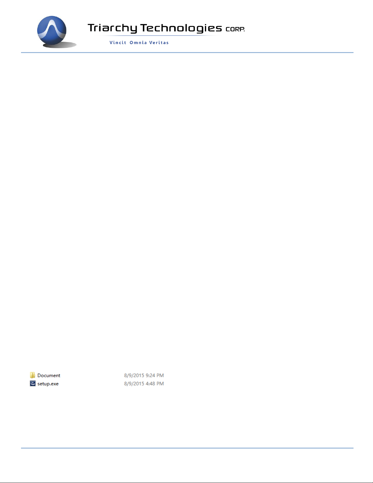
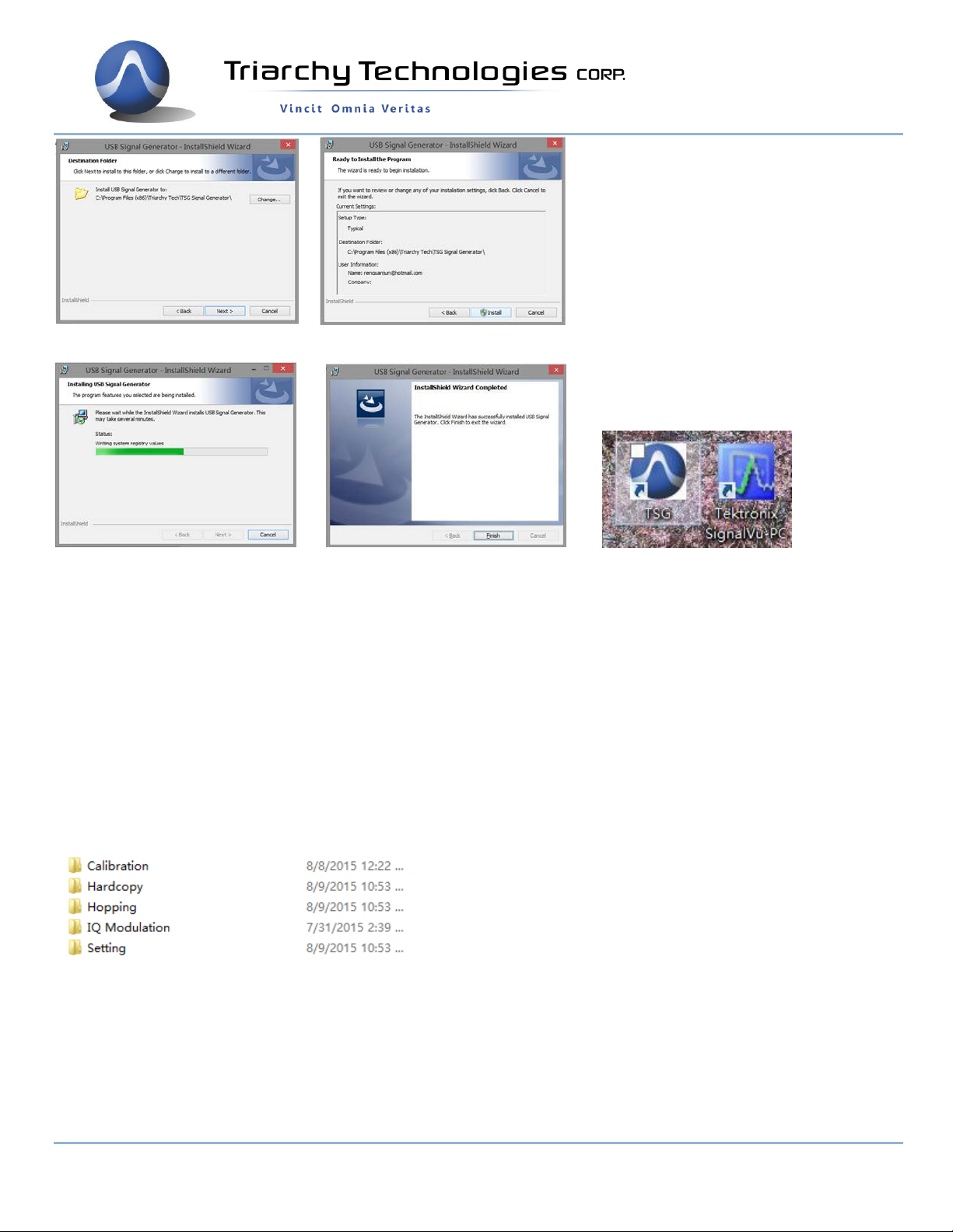
Open the CD, go into the SW file folder, you can find setup.exe and Document folder.
If you want copy the setup.exe to any PC any folder to install the program, please make sure that Document folder shall
be copied and located at same folder as setup.exe file.
When you finished the installation, the TSG ICON will be shown on the desk
Page 10 of 33
9248 163 Street
Surrey, BC V4N 3C9
604-637-2167
info@triarchytech.com
After installation, the program file will be installed at program file folder.
C:\Program Files (x86)\Triarchy Tech\USB Vector Signal Generator
The application data will be generated at Document folder:
C:\Users\Username\Documents\Triarchy Tech\TSG Signal Generator
Customer need to check the application data at document folder.
Calibration folder stores the calibration file. There multiple calibration files in the folder. You can generate new
calibration file and stored in same folder.
Hardcopy folder: stores the image file which generated by hardcopy key.
Hopping folder: stores the hopping files.
IQ Modulation folder: stores all the modulation file.
Setting folder: save file, preset, and specific setting are stored in it, then using load key to resumed the previous setting.
You can add more files into document folder, so that more modulation signal can be generated.
2.2 Uninstall PC Application
Uninstall TSG ICON, click it to uninstall.

Page 11 of 33
9248 163 Street
Surrey, BC V4N 3C9
604-637-2167
info@triarchytech.com
You also can use control panel to uninstall the TSG program.
2.3 First Working Example
During the first time using VSG6G1 product: turn off the TSG PC application first, then connect VSG6G1 to PC via USB
cable, PC will install the USB device hardware configuration.
Then open the TSG PC application, the USB connection area will show the device model, S/N and connection status.
Connect device output to Spectrum analyzer. Then click RF off ,RF output will be on.
Spectrum analyzer will shows the signal waveform:
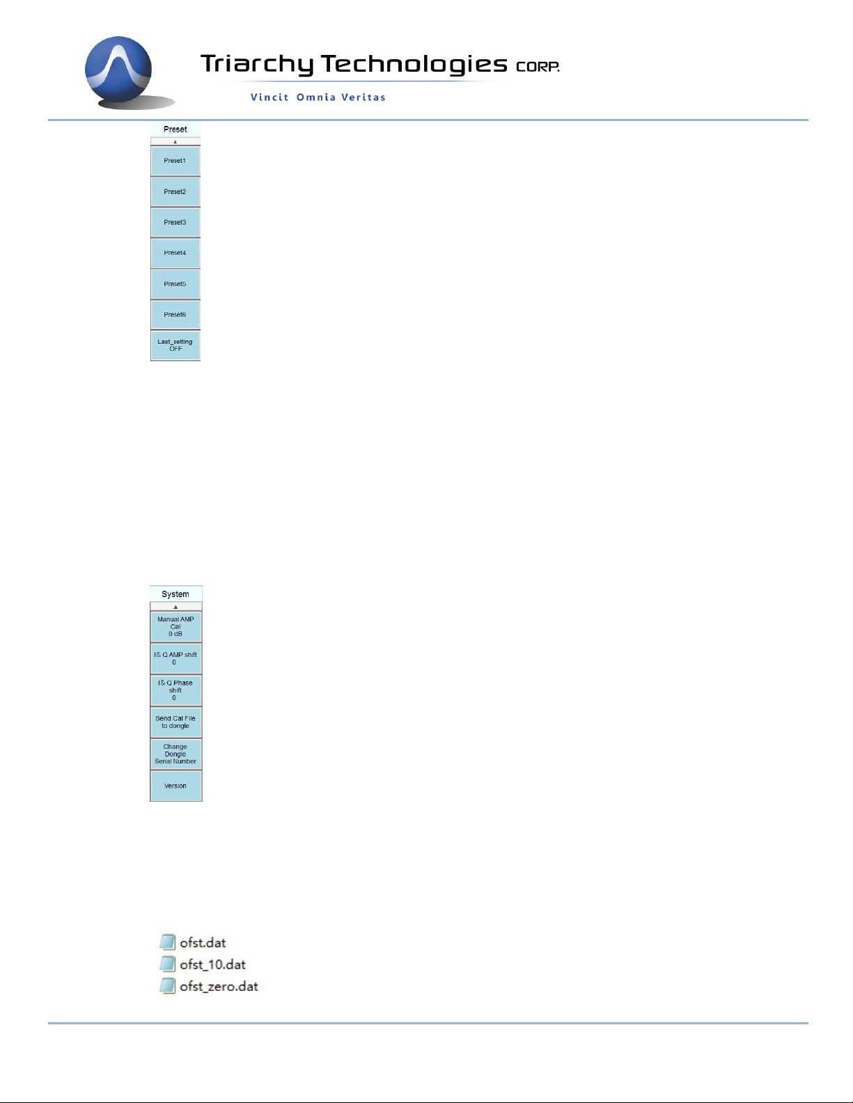
2.4 TSG Utility keys setting
Preset
When clicking the Preset key, the second function key will be shown:
Page 12 of 33
9248 163 Street
Surrey, BC V4N 3C9
604-637-2167
info@triarchytech.com
Local
Last setting key select to ON, when TSG program turn on or USB device plug off and on, all system
setting will go to last setting.
Last setting key select to OFF, when TSG program turn on or USB device plug off and on, all system
setting will go to preset 1 status.
Preset x (x=1~6) can be clicked, then system setting will go into the preset x status.
Preset x can be setup at Load Save key
Reserve to Remote function.
Hardcopy
Click hard copy, the image of setting will be save at document folder:
System
When clicking the System key, the second function key will shown:
Manual AMP Cal:
The value can be input, when output terminal attach the attenuator or cable path loss.
I&Q AMP shift and I&Q Phase shift:
This function is used for compensation of I&Q error in RF path to improve the EVM performance.
Application note will discuss this item in more detail.
Send Cal File to Dongle:
Three calibration file can be selected in the calibration folder.

Page 13 of 33
9248 163 Street
Surrey, BC V4N 3C9
604-637-2167
info@triarchytech.com
ofst.dat is calibration file. It is the default setup in the dongle, if you want setup another calibration, you
need to setup this calibration file again to resume the calibration condition.
ofst._zero.dat is un calibration, open this file. The output level will be maximum, such as you can get
15dBm output at 1GHz
ofst_10.dat is calibration with 10dB level decrease. EVM performance can be improved when using this
file.
Change the dongle series number:
It need passwords to change the series number. This function is reserved for manufacture use.
Version:
Show the current TSG version number
Load Save:
`When clicking the System key, the second function key will shown:
Save Setting:
To save the current setting status into file, it can be resume setting by Load setting.
If saving the file into preset folder, and name as Presetx_mode.txt, the preset set can be updated by
save setting key.
Load Setting:
To recall the setting file by Load setting, the old setting status will be represent into current setting.
Flash ON/OFF
This is selection key, when select Flash ON, all the command and setting will be stored at flash memory,
when TSG program turn off, then device plug off PC and plug on 5V power adapter, the device will be
working on the previous setting. So that Device can standalone work without PC, when select Flash off,
all the command and setting will stored at RAM, it is normal working mode, please select Flash off, if you
don’t want to work as standalone mode.
RF ON/OFF
This is selection key, the Preset 1 will set this key to RF OFF, after you connect RF output terminal with
UUT, then you can set this key to RF ON. Please note, don’t turn on the RF output when RF output
terminal is open.
3 Operations
3.1 CW Signal Output
1: in function keys, in second function keys.
2: in function keys, 1.1GHz in second function keys.
3: in function keys, 5dBm in second function keys.
4: in utility keys, measure the RF output by Spectrum analyzer.
Page 14 of 33
9248 163 Street
Surrey, BC V4N 3C9
604-637-2167
info@triarchytech.com
Spectrum from HP8566A
RBW=1KHz, phase noise is -90dBc/Hz @10KHz
RBW=10KHz, phase noise is -108dBc/Hz @100KHz
RBW=100KHz, phase noise is -120dBc/Hz @1MHz
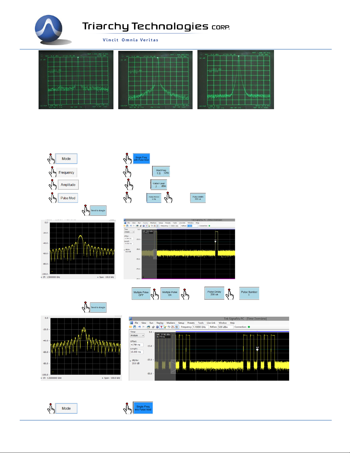
3.2 Pulse modulation Signal Output
1: in function keys, in second function keys.
2: in function keys, 1.5GHz in second function keys.
3: in function keys, 2dBm in second function keys.
4: in function keys, 5ms , 200us in second function keys.
After all setting ,commands will send to dongle.
Spectrum from RSA306 RF Time waveform from RSA306
5: The multiple pulse can be setup , 200us , 5 in second function keys.
After all setting ,commands will send to dongle.
Spectrum from RSA306 RF time waveform from RSA306
3.3 AM Signal Output
1: in function keys, in second function keys.

Page 15 of 33
9248 163 Street
Surrey, BC V4N 3C9
604-637-2167
info@triarchytech.com
2: in function keys, 1.5GHz in second function keys.
3: in function keys, 0dBm in second function keys.
4: in function keys, in second function keys.
3: in function keys, in second function keys.
3: in function keys, 2000 in second function keys.
Status block will be:
AM modulation frequency will be 1KHz, modulation index is 90%, changing I&Q step count will change AM
modulation frequency
Spectrum from RSA306 Demod waveform from RSA306 I&Q raw data from TSG
3.4 FM Signal Output
1: in function keys, in second function keys.
2: in function keys, 1.5GHz in second function keys.
3: in function keys, 0dBm in second function keys.
4: in function keys, in second function keys.
3: in function keys, in second function keys.
3: in function keys, 50 in second function keys.
Status block will be:
FM modulation frequency will be 2KHz, modulation index is 20, the deviation frequency will be +/-40KHz,
changing I&Q step count will change FM modulation frequency

Page 16 of 33
9248 163 Street
Surrey, BC V4N 3C9
604-637-2167
info@triarchytech.com
Spectrum from RSA306 Demodulation waveform from RSA306 I&Q raw data from TSG
3.5 Frequency shift
Analog modulation is using I&Q raw data file, AM/FM/PM modulation index can be changed by using this raw
data file, signal modulation repeat frequency can depended on the I&Q step count and I&Q data amount. It also
can generate a lot of modulation signal by defining the raw data file.
Following example is narrow band RF noise signal. I&Q will be random noise data, I&Q clock will be 2MHz, so
that 2MHz bandwidth noise will at 1GHz.
1: in function keys, in second function keys.
2: in function keys, 1GHz in second function keys.
3: in function keys, 0dBm in second function keys.
4: in function keys, in second function keys.
5: in function keys, in second function keys.
6: in function keys, 100 in second function keys.
Status block will be:
Frequency shift at 1GHz.
No shift in Frequency Shift +1KHz in frequency Shift -1KHz in frequency
Setup I&Q step count to 1000, the shift will be 100Hz,
I&Q step count to 10000, the shift will be 10Hz,
3.6 Analog Modulation with I&Q raw data file

Page 17 of 33
9248 163 Street
Surrey, BC V4N 3C9
604-637-2167
info@triarchytech.com
Analog modulation is using I&Q raw data file, AM/FM/PM modulation index can be changed by using this raw
data file, signal modulation repeat frequency can depended on the I&Q step count and I&Q data amount. It can
also generate a lot of modulation signal by defining the raw data file.
Following example is narrow band RF noise signal. I&Q will be rand noise data, I&Q clock will be 2MHz, so that
2MHz bandwidth noise will be at 1GHz.
1: in function keys, in second function keys.
2: in function keys, 1GHz in second function keys.
3: in function keys, 0dBm in second function keys.
4: in function keys, in second function keys.
5: in function keys, in second function keys.
6: From pop window to select PN4000.txt file in PN folder.
3: in function keys, 36 in second function keys.
Status block will be:
RF narrow band noise is generated at 1GHz.
Spectrum from RSA306 I&Q Raw data from TSG I&Q constellation from TSG
3.7 GMSK signal Output
1: in function keys, in second function keys.
2: in function keys, 1.5GHz in second function keys.
3: in function keys, 0dBm in second function keys.
4: in function keys, in second function keys.

Page 18 of 33
9248 163 Street
Surrey, BC V4N 3C9
604-637-2167
info@triarchytech.com
3: in function keys, in second function keys.
3: in function keys, 72 in second function keys.
Status block will be:
GMSK data rate will be 100KHz/b, changing I&Q step count will change GMSK data rate.
Demod I&Q vs Time from RSA306 Eye Diagram from RSA306 Trellis Diagram from RSA306
3.8 FSK signal Output
1: in function keys, in second function keys.
2: in function keys, 1GHz in second function keys.
3: in function keys, 0dBm in second function keys.
4: in function keys, in second function keys.
5: in function keys, in second function keys.
6: in function keys, 50 in second function keys.
Status block will be:
FSK data rate will be 40KHz/b, changing I&Q step count will change FSK data rate.
Demod I&Q vs Time from RSA306 Eye Diagram from RSA306 Constellation Diagram from RSA306

Page 19 of 33
9248 163 Street
Surrey, BC V4N 3C9
604-637-2167
info@triarchytech.com
3.9 Digital Modulation with I&Q Engine
Working on I&Q file,most of all digital modulation can be generated, save the I&Q file into Digital modulation
sub folder, click the ,I&Q file can be input. The 4FSK file is example in following section.
1: in function keys, in second function keys.
2: in function keys, 1GHz in second function keys.
3: in function keys, 0dBm in second function keys.
4: in function keys, in second function keys.
5: in function keys, in second function keys.
6: From pop window to select IQ 4FSK.txt file.
7: in function keys, 50 in second function keys.
Status block will be:
4FSK data rate will be 40KHz/b, changing I&Q step count will change 4FSK data rate.
I&Q pattern from TSG Eye Diagram from RSA306 Constellation Diagram from RSA306
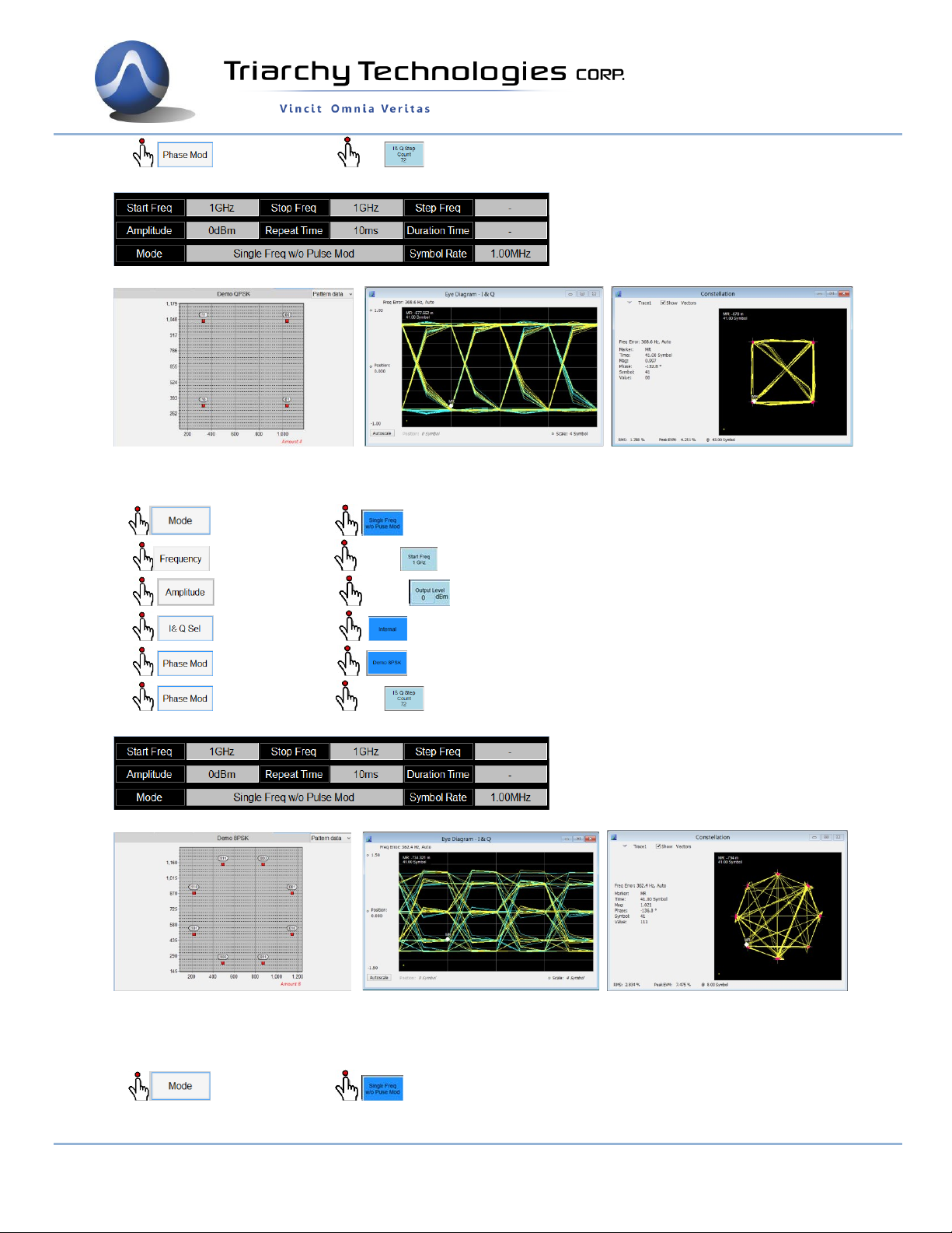
3.10 QPSK Signal output
1: in function keys, in second function keys.
2: in function keys, 1GHz in second function keys.
3: in function keys, 0dBm in second function keys.
4: in function keys, in second function keys.
5: in function keys, in second function keys.
Page 20 of 33
9248 163 Street
Surrey, BC V4N 3C9
604-637-2167
info@triarchytech.com
6: in function keys, 72 in second function keys.
Status block will be:
QPSK data rate will be 4MHz/b, changing I&Q step count will change QPSK data rate.
Constellation Diagram from TSG Eye Diagram from RSA306 Constellation Diagram from RSA306
3.11 8PSK Signal output
1: in function keys, in second function keys.
2: in function keys, 1GHz in second function keys.
3: in function keys, 0dBm in second function keys.
4: in function keys, in second function keys.
5: in function keys, in second function keys.
6: in function keys, 72 in second function keys.
Status block will be:
8PSK data rate will be 8MHz/b, changing I&Q step count will change QPSK data rate.
Constellation Diagram from TSG Eye Diagram from RSA306 Constellation Diagram from RSA306
3.12 16QAM Signal output
1: in function keys, in second function keys.
This manual suits for next models
2
Table of contents
Other Triarchy Technologies Inverter manuals


