Epcom EPIG5K User manual
EPIG5K

- 1 -
1Manual Instruction
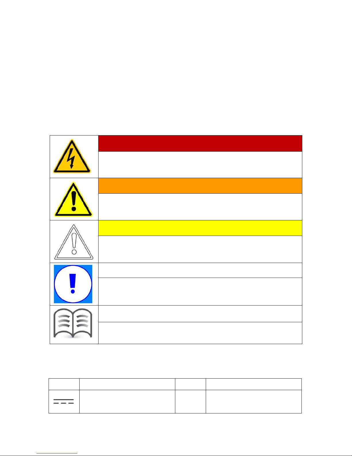
1.1 Symbols used in this manual
This manual contains important instructions for safety and operation which must be
understood and carefully followed during installation and maintenance of the equipment.
In order to reduce the risk of electric shock and to be sure that the equipment is correctly
installed and ready to operate, special safety symbols are used in the manual to highlight
potential safety risks or useful information. The symbols are the following:
DANGER!
DANGER indicates a hazardous situation which, if not avoided, will result
in death or serious injury.
WARNING!
WARNING indicates a hazardous situation which, if not avoided, could
result in death or serious injury.
CAUTION!
CAUTION indicates a hazardous situation which, if not avoided, could
result in minor or moderate injury.
NOTICE
NOTICE indicates a situation which, if not avoided, could result in property
damage.
Information
Information provides tips that are valuable for the optimal installation and
operation of your product.
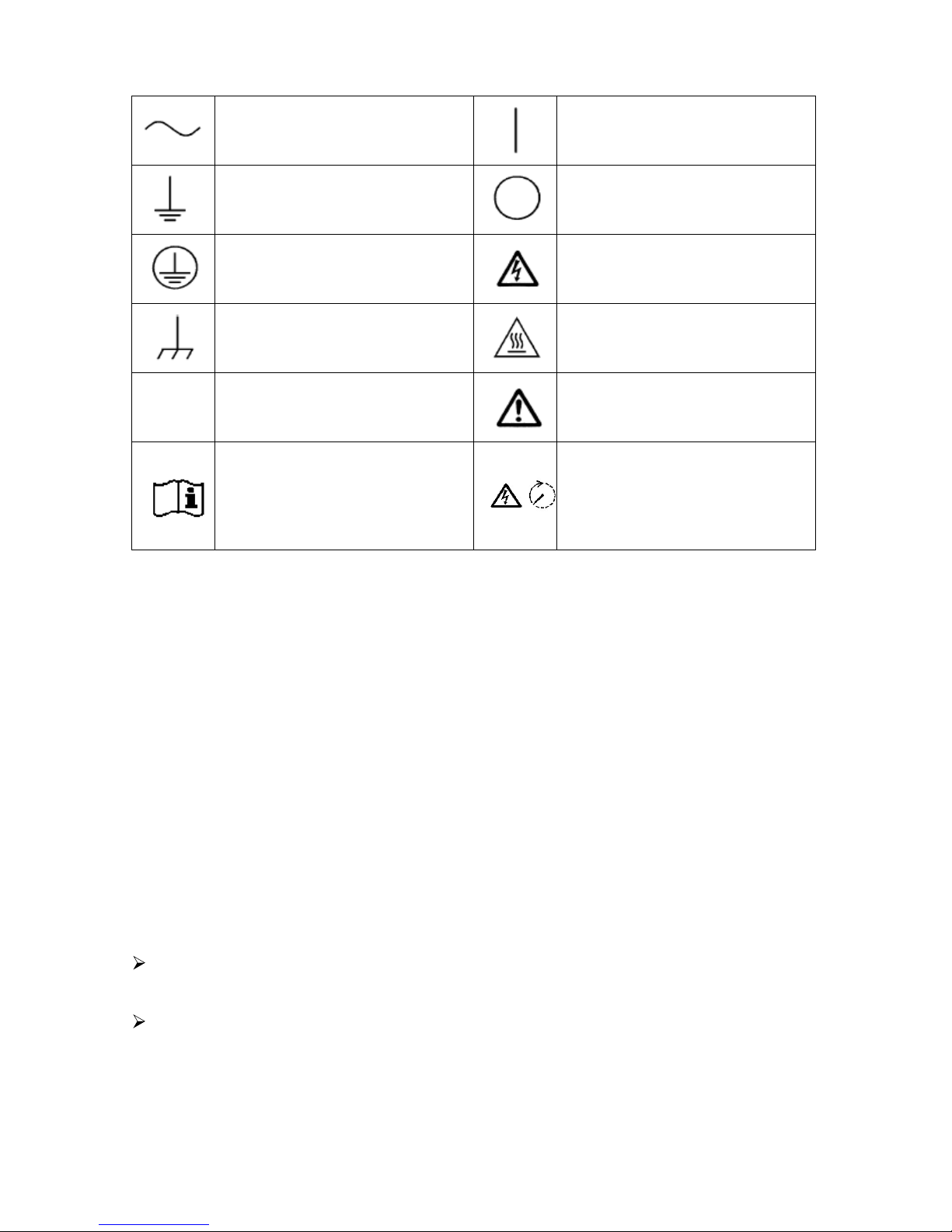
This manual and machine may also use the following electrical symbols and
identification. Description as follows:
Symbol Description Symbol Description
Direct current —Continuous negative voltage pole
- 2 -
Alternating current
On (Supply)
Earth (ground) TERMINAL Off (Supply)
Protective conductor TERMINAL Caution, risk of electric shock
Frame or chassis TERMINAL Caution, hot surface
+
Continuous positive voltage pole Caution, risk of danger
Refer to the operating instructions Caution, risk of electric shock.
Energy storage timed discharge
(time to be indicated adjacent to
the symbol)
1.2 User group
Please read this manual thoroughly. This manual contains information about
EPIG5K single phase grid-connected inverter of transportation,
installation, operation, maintenance and troubleshooting.
1.3 Validity
This manual applies to EPIG5K grid-connected inverter.
2Safety Instructions
The inverter must be installed by a qualified electrician who is responsible for
observing existing standards and regulations.
Read and understand all the instructions contained in this manual and become familiar
with the safety symbols in the relevant paragraphs before you install and operate the
equipment.

- 3 -
¾The connection to the distribution grid must be done only after receiving approval
from the distribution utility as required by national and state interconnection
regulations, and can be done only by qualified personnel.
¾Comply with all corresponding marks and symbols present on each device. During
operation, make sure that all covers and doors are closed.
DANGER!
Unauthorized removal of the necessary protections, improper use, wrong
installation or wrong operation may lead to serious damage to people and
objects.
Transport, handling, installation, start-up and maintenance must be performed
by qualified and trained personnel.
DANGER!
After disconnecting the inverter from distribution grid, wait for 60 seconds for
capacitors to discharge before servicing or touching any live part and electric
connection.
WARNING!
The installation must be performed in full compliance with national and local
standards and regulations.
WARNING!
When the photovoltaic array is exposed to light, it supplies a DC voltage to the
PCE. To ensure a safe work environment, keep the whole surface of the
photovoltaic panel covered with material opaque to solar radiation before
connecting panel to equipment.
WARNING!
Make sure the DC input voltage does not exceed 520V, or it may damage this
inverter permanently and cause other losses.
- 4 -
WARNING!
Do not change the internal components of the inverter without permission.
WARNING!
If the equipment is used in a manner not specified by the manufacturer, the
protection provided by the equipment may be impaired.
3Product Description
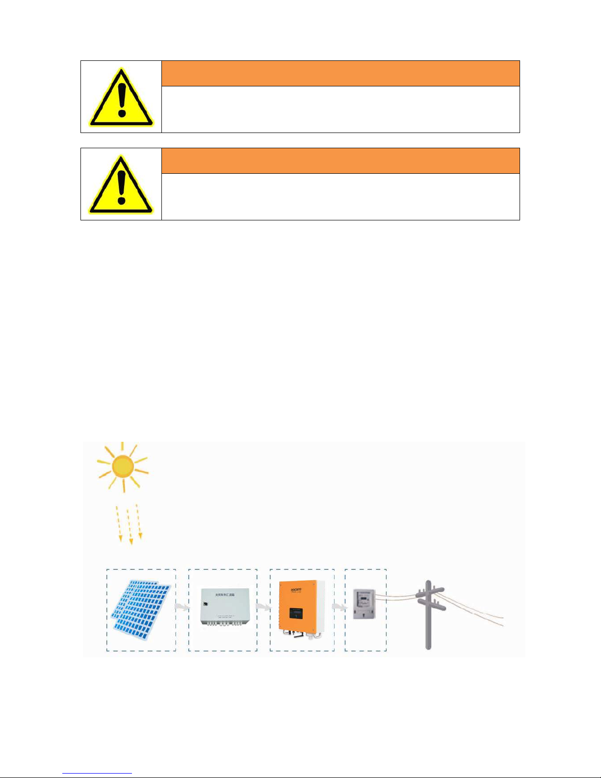
3.1 Photovoltaic/PV grid-connected system
PV grid-connected system consists of PV modules, grid-connected inverters,
metering device and power distribution system (Figure 1).
The solar energy is converted into DC current by PV modules and then feeding into
the local power grid network by the grid-connected inverter which synchronizing the
frequency, phase and pure sine waveform with the power network.
Figure 1 PV grid-connected system
PV modules
Combinerbox
Inverter
Metering Power
g
rid

- 5 -
3.2 Basic structure
Figure 2 Working principle of EPIG5K
This inverter is designed with boost+ inverter topology. The DC filter prevents the
penetration of high-frequency line-bound interference. After the voltage equalization by
the capacitor, the inverter converts the direct current from solar power system into
alternating current with the same frequency and phase with the grid. The downstream LC
filter has the purpose of equaling the current. Finally the current flows to the utility grid.
In order to make maximum output power of photovoltaic array, it adopt advanced
MPPT algorithm in the DC boost side.
3.3 Appearance, dimension and weight
3.3.1 Appearance
Information
Inverter with 4 colors for customer choice.
Respectively are: red, green, yellow, gray
EMI BOOST DC/AC EMI
PV+
P
V
-
L
N
G
Button
LCD
- 6 -
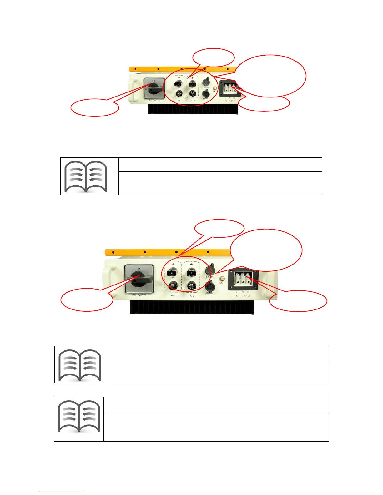
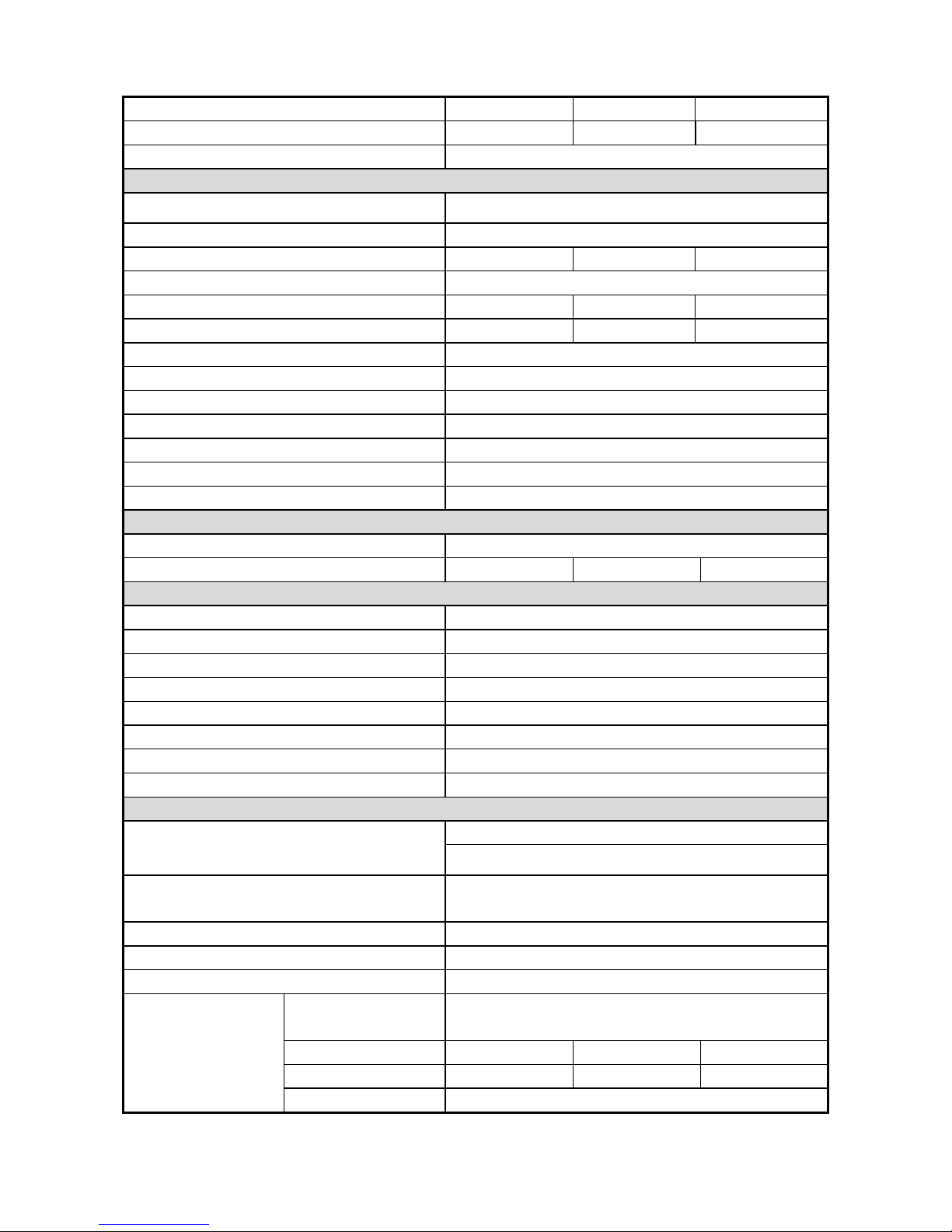
Figure 3 External Appearance of (3,*.
Information
Installation method as shown in the 5.5.1 of “Ⅰ”.
Figure 4 External Appearance of the special (3,*.
Information
Installation method as shown in the 5.5.1 of “Ⅱ”.
Information
The PV input has one channel of MPPT which consists of three pairs of
terminals, so there can be max three PV strings connecting to the channel.
DC switch
PV Input
RS485
Communication
Terminal
AC Output
PV Input
RS485
Communication
Terminal
AC Output
DC switch

- 7 -
3.3.2 Dimensions and weight
Figure 5 Dimensions of (3,*.
The dimensions of the (3,*. are mm ×mm
×mm (W×H×D). The inverter weighs approximately kg. Please take this dimension
and weight into consideration during shipping, moving and installation.
3.4 Technical data
Type
Specification
(3,*.
Input
CDV004egatlovCDlanimoN
V051egnaregatlovgnitarepO ~500V
025egatlovtupniVPxaM
A22tnerructiucric-trohsVP
A02
wk3.5
Peak DC short-circuit feedback current 159 A peak impulse (duration time 2ms)
DC to case insulation voltage Basic insulation 1800Vdc/1min
MPPT
460
390 165
- 8 -
Full-load MPPT voltage range 250~420VDC
Number of MPP-Trackers 1
MPPT efficiency (static) >99%
Output (AC)
Working manner continuous
Output phase number single phase and 3 line
Nominal AC power 5kw
Nominal AC voltage 230Vac
Nominal AC current 22A
Max allowable AC current 25A
Nominal frequency 0Hz
Distortion (THD)<3% (nominal power)
Output voltage DC ponderance <0.5%(nominal output power)
Power factor (cos phi) >0.99
Output current limit When overload or short circuit
Inverter short-circuit current 130 A peak impulse (duration time 2ms)
AC to case insulation voltage Basic insulation 1500Vdc/1min
Efficiency
Max efficiency 97.5%
Euro efficiency 96.5%
General Requirements
Standby consumption 12w
Night consumption 0W
Grid connected method Direct connect(transformerless)
Ingress protection IP65
Protection degree Type I
RS485 to DC input insulation voltage Reinforce insulation 3000Vdc/1min
Mean Time Between Failures(MTBF)40,000 hours
Working life 20 years
Protection
Input protection
Reverse connect protection
Short-circuit protection
DC to ground insulation resistance detecting and
protection
>800kohm
Output protection Short-circuit protection
Grid monitoring Voltage monitoring,Frequency monitoring
Input lower /over-voltage protection points 150V/530V
Grid lower /over-voltage
protection points
TUV: DIN VDE
0126-1-1 184V/253V
G59/2 200V/253V
G83-1 X
AS4777 205V/265V
- 9 -
Grid lower
/over-frequency
protection points
TUV: DIN VDE
0126-1-1 50.2Hz/47.5Hz
G59/2 +]
G83-1 X
AS4777 +]
Residual current monitoring Comply with DIN VDE 0126-1-1
Fault current monitoring Comply with DIN VDE 0126-1-1
Anti-islanding protection Comply with DIN VDE 0126-1-1
Standard
Safety IEC 62109-1,IEC 62109-2
certification VDE/TUV/CE
EMC EN61000-6-1,EN61000-1-2;Class B
EMI EN61000-6-3,EN61000-1-4
Functional safety and anti-islanding DIN VDE0126-1-1/AS4777/G83-1/G59-2
Remark: Europe efficiency calculate :
%100%50%30%20%10%5 20.048.010.013.006.003.0
ηηηηηηη
+++++=
Euro
Others
Items Specification Remarks
Radiation noise CISPR22 Class A
Conducted noise CISPR22 Class A
AC short circuit protection Yes(current limited)
Lightning resistant 1.2uS X 50uS 5kV DC/AC to ground
ESD Protection Case to operational part 15kV System can work normally
Noise <50dB 1m
Vibration resistance JEC-5917
5Hz 1G 30times at X・Y direction
10Hz 1G 30times at X・Y direction
5Hz 0.5G 30times at Z direction
10Hz 0.5G 30times at Z direction
Durable years 20 years Average temperature 25℃12H/day
Environmental conditions
Items Specification Remarks
Operating temperature -20℃~ +50℃
Altitude 2000 m
Relative humidity 4% ~ 100 %
Noise level <50dB 1m
Cooling Method Natural cooling
*Above data just for reference. If there is a change, please refer to the machine.

- 10 -
4Installation
4.1 Safety
DANGER! Danger to life due to fire or explosion!
Despite careful construction, electrical devices can cause fires.
• Do not mount the inverter on flammable construction materials.
• Do not install the inverter in areas where highly flammable materials are
stored.
• Do not install inverters in areas with a risk of explosion.
CAUTION! Risk of injury due to the heavy weight of the inverter.
•Take the weight of the inverter into account for transport.
• Select a suitable mounting location and mounting surface.
• When mounting the rear panel, use fastening material suitable for the
mounting surface.
• Two people are needed to mount the inverter.
CAUTION! Danger of burn injuries due to hot enclosure parts!
Mount the inverter in such a way that it cannot be touched
inadvertently.
4.2 Selecting the mounting location
Consider the following points when selecting where to install:
¾The protection level of this product is IP65, so it can be installed outdoors.
¾Vertical installation.
¾Do not install horizontally.
¾Select a well-ventilated location sheltered from direct sun radiation. Choose a
location that allows unobstructed airflow around the inverter.
¾The operation will generate some noise (<50dB), so please install away from the
people living space.
¾Mount on a solid surface. Ensure the installation place does not wobble.

- 11 -
¾The machine should be installed in the reinforced concrete wall or metal wall that
can bear the weight of the inverter. It should not be installed in the wood to keep
from danger of fire.
¾Height from ground level should be such as to ensure that the display and status
LEDs are easy to read.
¾Ensure the temperature range can keep in the range (-25°C — +50°C)
¾Allow sufficient room around the inverter to enable easy installation and removal
from the mounting surface.
¾There must be sufficient clearance between the individual inverters so that the
¾cooling air from the adjacent inverter is not drawn in.
NOTICE
Ambient temperature range shall be -20°C to +50°C. It will affect the
power output when the temperature exceeds the limit.
NOTICE
Environment humidity must be in the range of 4% ~ 100%.
4.3 Wall mounting
Included in the shipping package is a mounting kit with 6 screws and 6 wall plugs
provided for mounting the metal bracket to a concrete wall. The screws should be
mounted in the 6 holes present in the bracket (as Figure 5 shows).
After the bracket is secured to the wall, hang the inverter on the bracket. As shown
below.
Figure 6 Installation for cabinet
Bracket
Rear panel

- 12 -
The inverter needs to be lifted up and then slid down over the hooks making sure that
the connecting points in the bracket and in the back of the inverter engage properly.
5Electrical Connection
5.1 General safety instruction
DANGER!
Improper operation during the wiring process can cause fatal injury to
operator or unrecoverable damage to the inverter.
Only qualified personnel can perform the wiring work.
DANGER!
Before you connect the inverter, disconnect the AC and DC sides from all
power sources and secure them against being inadvertently switched back on.
WARNING!
Always respect the nominal ratings of voltage and current specified in section
4 (Technical Data) when designing your system. Please observe these
considerations when designing the photovoltaic field:
Maximum DC voltage input to each MPPT circuit: 520 V
Maximum DC current input to each MPPT circuit:
20A for (3,*.
WARNING!
Check the national and local standard regulations to make sure that your
electrical installation design is in compliance with them.
NOTICE
All cables must be firmly attached, undamaged, properly insulated and
adequately dimensioned.

- 13 -
5.2 The electrical connection diagram overview
Inverter electrical connection includes PV side electrical connections, AC side
electrical connections and communication cable electrical connection.
No. Item Remarks
A DC circuit breaker
Used as a protective device during electrical connection. User
must equips this device according to the maximum input voltage
and current. You must choose the external DC circuit breaker
whose rated current is 40A and the max breaking capacity can
reach more than 1kA.
B PV arrays
There are three pairs of input terminals in one MPPT channel for
the inverter. The allowable maximum open-circuit voltage of PV
arrays is 520V. And the allowable maximum short-circuit currents
of the connected modules is 22A.
C Remote PC User equips this device to monitor the state of the inverter.
D AC circuit breaker
Used as a protective device during electrical connection. You
must choose the external AC circuit breaker whose rated current
is 40A and the max breaking capacity can reach more than 2kA.
The PE cable should be connected reliably to the earth.
E Grid Rated voltage of each phase of the utility grid is 230V.

- 14 -
5.3 Cable requirements
All cables for PV power system are equipped with water-proof direct plug-in
connectors. You‘ll find these connectors in the package.
For electrical connection in the PV system described above, the cross section of all
cables used should not be smaller than the following requirements.
Terminals
Model
AC Output
DC Input 1
DC Input 2
DC Input 3
L N + - + - + -
EA5KLPV 10 10 10 10 10 10 10 10
There are three channels of DC input which can connect three PV strings. The red is
“+”, and the black is “-”. There is one channel of AC output, the red is L phase, the black
is N phase,and the yellow-green is PE.
NOTICE
The grid impedance of the AC cable must not exceed 1 Ohm. Otherwise, the
inverter will disconnect at full feed capacity due to excessive voltage at the
feed-in point.
5.4 Connection of the PV generator (DC)
5.4.1 DC input wiring
Wire Size
(mm)
AWG
Negative
terminal
Positive
terminal

- 15 -
5.4.2 DC connection
Step 1: Assemble DC cable to connector at the inverter side. See “5.4.1 DC Input
Wiring”.
Step 2: Disconnect DC and AC circuit breakers.
Step 3: Check connection cable of one PV array string for correct polarity and that
the maximum input open circuit voltage does not exceed 520V.
Step 4: Measure DC voltage between positive terminal of the PV string and Earth
and DC voltage between negative terminal of the PV string and Earth. If the two voltages
are constant and not zero, there is an insulation failure somewhere in this PV string.

- 16 -
Step 5: Plug DC positive and negative connector into corresponding terminals. If it
makes a click sound, it means DC connector has attached to terminals.
Step 6: Link the rest of the two photovoltaic module strings in the same manner.
NOTICE
To create the sealing of the inverter, all the DC inputs that are not required
have to be closed as follows:
– Insert the sealing plugs provided into the DC plug connectors that are not
required. Do not insert the sealing plus into the DC inputs on the inverter.
– Insert the DC plug connectors with sealing plugs into the corresponding
DC inputs on the inverter.
5.5 Connecting inverter to AC grid
5.5.1 AC output wiring
NOTICE
As the series of products, in the KWpower section, there are two kinds
of AC output terminals, So,in the installation of (3,*. machine, please
install personnel to select the corresponding installation method
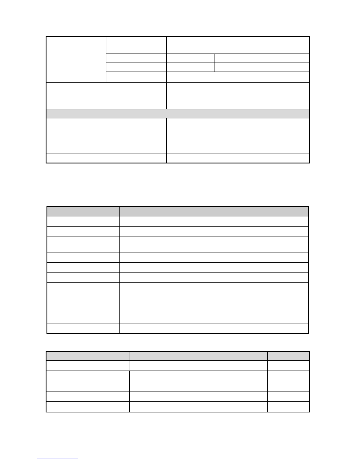
Ⅰ: Do not plug in AC output terminal installation method
NOTICE
The following installation method applicable to the series, with the
exception of the special (3,*.; External Appearance as shown in
Figure 3
- 17 -
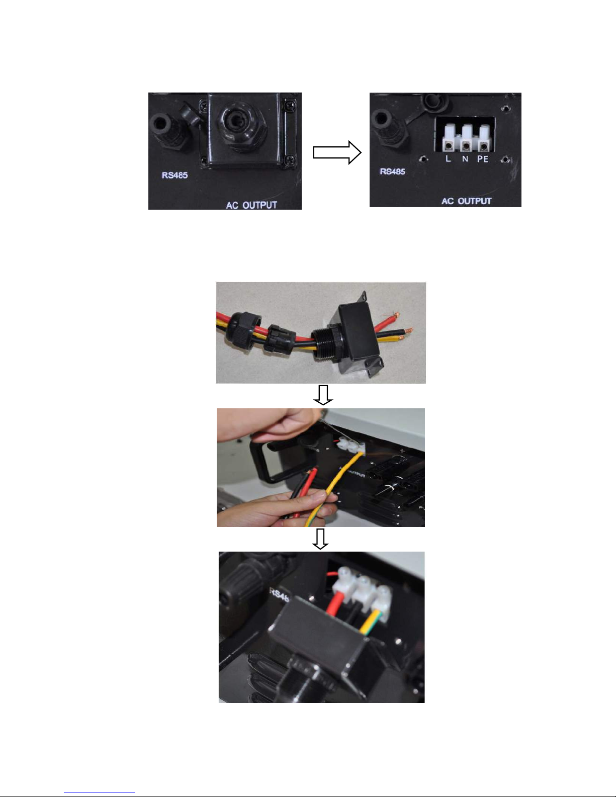
Step 1: Unscrew AC output cover at the downside of the machine.
Step 2: Insert stripped AC cables of appropriate size into the cable glands. Fix the
phase cables into corresponding terminals with screwdriver according to marks. Fix
ground cable into the ground terminal.

- 18 -
Step 3: Screw the AC output cover.
Step 4: Tighten the cable gland in clockwise direction.
Ⅱ: Pluggable AC output terminal installation method
NOTICE
The following installation method is only applicable to the series of
special (3,*. ,External Appearance as shown in Figure 4.
Table of contents
Other Epcom Inverter manuals


Popular Inverter manuals by other brands


Sungrow
Sungrow SG2.0RS-S user manual

Mitsubishi Heavy Industries
Mitsubishi Heavy Industries SRR25ZM-S Technical manual

Turbo Energy
Turbo Energy 1600 Series instruction manual

Circutor
Circutor SVGm instruction manual

Turbo Energy
Turbo Energy Lithium Series instruction manual

Black & Decker
Black & Decker BDPC200 manual


