TRIATEK FMS-2000M Lite User manual

1
FMS-2000M Lite
Critical Environment Monitor
LIT-12013692
December 2020
Installation Guide

FMS-2000M Lite
LIT-12013692
2
Risk of Personal Injury or Property Damage.
For use in a controlled environment only. Refer to installation instructions for environmental conditions.
Risk of Electric Shock.
Disconnect the power supply before making electrical connections. Contact with components carrying hazardous voltage can cause
electric shock and may result in severe personal injury or death.
Risk of Property Damage.
Use a 24 VAC 30 VA Class 2, LPS or Limited Energy transformer for the monitor. Failure to follow the wiring diagrams may result in
damage to the monitor and could void your warranty.
Risk of Property Damage.
Do not apply power to the system before checking all wiring connections. Short circuited or improperly connected wires may result in
permanent damage to the equipment.
Risk of Property Damage.
Do not run low-voltage cable in the same conduit or wiring troughs with high-voltage wires. Running low- and high-voltage wires in the
same conduit or wiring troughs may damage the equipment or cause system malfunction.
Risk of Property Damage.
Ensure that the power source conforms to the requirements of the equipment. Failure to use a correct power source may result in
permanent damage to the equipment.
Risk of Property Damage.
Do not run network communication cables in the same conduit, raceway, or panel with any high-voltage (greater than 30 VAC) wiring.
Isolate all network wiring and all network devices from high-voltage wiring and equipment. Failure to isolate network wiring and
network devices from high-voltage wiring and equipment can result in damage to network devices or poor network performance.
Risk of Property Damage.
Label all wires prior to disconnecting the equipment. Failure to label the wires may cause improper equipment operation after
reconnecting the equipment.
Risk of Property Damage.
Do not connect the 24 VAC power supply directly to the FMS-2000M Lite display four-position terminal block. You must terminate the
power at the remote sensor's nine-position terminal block on the +Vin and -Vin terminals. Failure to follow the wiring instructions may
cause permanent damage to the FMS-2000M Lite monitor and void your warranty.
IMPORTANT: Do not install or use this FMS-2000M Lite Critical Environment Monitor in or near environments where corrosive
substances or vapors could be present. Exposure of the FMS-2000M Lite monitor to corrosive environments may damage the device’s
internal components and will void the warranty.
IMPORTANT: Install the FMS-2000M Lite Critical Environment Monitor with a Class 2, Limited Energy, or LPS isolated power supply and
connect it to an electrical circuit protected by a minimum 20 A circuit breaker. Mount the circuit breaker in an approved electrical enclosure
located separately, but in close proximity, to the FMS-2000M Lite monitor.
IMPORTANT: Do not install this FMS-2000M Lite Critical Environment Monitor in condensing, wet, or damp environments. Moisture may
cause damage to the FMS-2000M Lite monitor.

FMS-2000M Lite
LIT-12013692
3
IMPORTANT: Make all wiring connections in accordance with the National Electrical Code and local regulations. Use proper Electrostatic
Discharge (ESD) precautions during installation and servicing to avoid damaging the electronic circuits of the FMS-2000M Lite Critical
Environment Monitor.
IMPORTANT: Maintain proper polarity and voltage or current ratings. Improper polarity or exceeding the voltage or current ratings will
void the warranty.
IMPORTANT: Do not install the FMS-2000M Lite Critical Environment Monitor where the maximum temperature exceeds 125°F (52°C).
Installing the device where maximum temperatures exceed 125°F (52°C) may cause damage to the FMS-2000M Lite Critical Environment
Monitor and may void the warranty.
IMPORTANT:
personnel. Carefully follow all instructions in this document and all instructions for the FMS-2000M Lite Critical Environment Monitor.
IMPORTANT: Use copper conductors only. Make all wiring connections in accordance with local, national, and regional regulations. Do
not exceed the FMS-2000M Lite Critical Environment Monitor’s electrical ratings.

FMS-2000M Lite
LIT-12013692
4
Risque de blessure corporelle ou de dommages matériels.
Pour utilisation dans un environnement contrôlé uniquement. Consulter le guide d’installation pour les conditions environnementales.
Risque de décharge électrique.
dangereuses risque d’entraîner une décharge électrique et de provoquer des blessures graves, voire mortelles.
Risque de dégâts matériels.
Utilisez un transformateur de classe 2 à 24 V CA 30 VA, à limitation d’alimentation ou LPS pour le moniteur. Ne pas respecter les
schémas de câblage peut causer des dommages au moniteur et peut annuler votre garantie.
Risque de dégâts matériels.
connectés de façon incorrecte risquent d’endommager irrémédiablement l’équipement.
Risque de dégâts matériels.
Ne pas faire courir un câble basse tension dans les mêmes gaines ou goulottes électriques que des câbles haute tension.
l’équipement ou de provoquer des dysfonctionnements du système.
Risque de dégâts matériels.
d’alimentation électrique inappropriée risque d’endommager irrémédiablement l’équipement.
Risque de dégâts matériels.
Ne passez pas les câbles de communication réseau dans les mêmes gaines, chemins de câbles ou panneaux que les câbles à
haute tension (supérieure à 30 Vca). Isolez tous les câbles et appareils réseau des câbles et appareils à haute tension. Un défaut
d’isolement des câbles et appareils à haute tension peut provoquer des dommages aux appareils réseau et réduire les performances
du réseau.
Risque de dégâts matériels.
Etiquetez tous les câbles avant de débrancher l’équipement. Le non-respect de cette précaution peut amener un fonctionnement
anormal après redémarrage de l’équipement.
Risque de dégâts matériels.
Ne pas brancher le bloc d’alimentation de 24 V CA directement au bornier à quatre positions de l’écran du FMS-2000M Lite. Vous
devez raccorder l’alimentation aux bornes +Vin et -Vin du bornier à neuf positions du capteur à distance. Ne pas respecter les
instructions de câblage peut causer des dommages permanents au moniteur FMS-2000M Lite et annuler votre garantie.
IMPORTANT : N’installez ou n’utilisez pas FMS-2000M Lite Critical Environment Monitor dans, ou près, d’environnements où des
substances ou vapeurs corrosives peuvent être présentes. L’exposition du FMS-2000M Lite à des environnements corrosifs peut
endommager les composantes internes de l’appareil et annulera la garantie.
IMPORTANT : N’installez pas FMS-2000M Lite Critical Environment Monitor dans un environnement humide, mouillé ou il se produit de
la condensation. L’humidité peut causer des dommages au FMS-2000M Lite.
IMPORTANT : Installez le FMS-2000M Lite Critical Environment Monitor en utilisant un bloc d’alimentation de classe 2, à limitation
d’alimentation ou LPS et raccordez-le à un circuit électrique protégé par un disjoncteur d’un minimum de 20 A. Placez le disjoncteur du
FMS-2000M Lite dans un panneau électrique approuvé et situé à l’écart, mais à proximité.

FMS-2000M Lite
LIT-12013692
5
IMPORTANT :
réglementations locales. Utilisez une bonne protection contre les décharges électrostatiques (ESD) pendant l’installation et l’entretien
pour éviter d’endommager les circuits électroniques du FMS-2000M Lite Critical Environment Monitor.
IMPORTANT : Conservez la bonne polarité et la bonne tension ou le bon courant. Une mauvaise polarité ou le dépassement de la
tension ou du courant annulera la garantie.
IMPORTANT : N’installez pas le contrôleur d’environnement critique FMS-2000M Lite où la température maximum dépasse 52 °C
(125 °F). Installer l’appareil dans un environnement où la température maximum dépasse 52 °C (125 °F) peut endommager FMS-2000M
Lite Critical Environment Monitor et peut annuler la garantie.
IMPORTANT :
Environment Monitor.
IMPORTANT :
pour ce type de personnel. Suivez attentivement toutes les instructions de ce document et toutes les instructions du FMS-2000M Lite
Critical Environment Monitor.

FMS-2000M Lite
LIT-12013692
6
Introduction.................................................................................................................................................................................. 7
Location considerations............................................................................................................................................................. 8
Installing the FMS-2000M Lite Thin Mount display for a retrot application......................................................................... 9
Installing the FMS-2000M Lite Thin Mount display for a new application............................................................................ 11
Mounting the remote pressure sensor.................................................................................................................................... 15
Wiring the system and BACnet MS/TP communications ...................................................................................................... 17
Wiring one remote pressure sensor to the monitor............................................................................................................... 18
Conguring the display module settings................................................................................................................................ 20
BMS integration......................................................................................................................................................................... 20
Ordering information................................................................................................................................................................. 21
Cleaning the display.................................................................................................................................................................. 21
Technical specications ........................................................................................................................................................... 22
Repair information..................................................................................................................................................................... 23
Table of contents
FMS-2000M Lite
LIT-12013692
7
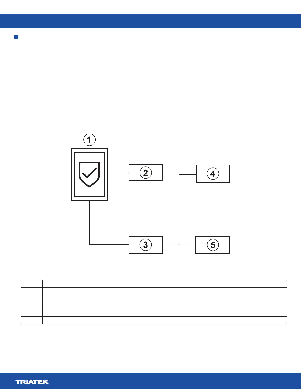
Introduction
touch screen.
administrators and one for restricted level users, such as nurses.
Item Component
1 FMS-2000M Lite monitor
2 Remote pressure sensor
3
4
5 Humidity sensor
Figure 1: FMS-2000M Lite system diagram
FMS-2000M Lite
LIT-12013692
8
Location considerations
location that you need. Place the sensors away from any moving air source like ceiling air registers, because this can cause unstable
sensor behavior.
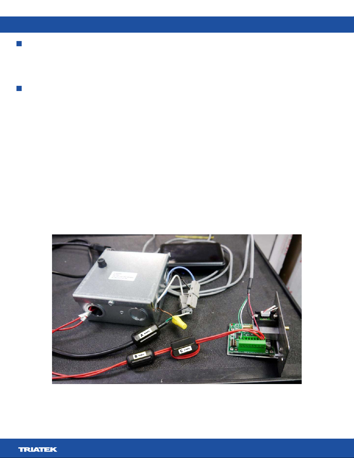
Ferrite Installation Instructions for FMS-2000M Lite series
included in the package are used in the installation as described below. Install the three cable ferrites included on the AC input cable to
the isolated power supply module, and on the wires that supply 24 VAC power to the pressure sensor module.
Power Supply Input Cable Ferrite
Install the cable ferrite A
clasp on the side of the ferrite to expose the core, place it on the power cable near to the power supply enclosure, and close the ferrite
around the cable. Ensure that the clasp latches securely.
Power Supply Output Cable Ferrites
Install the cable ferrite B
below. Locate this cable ferrite about 10-12 inches away from the end of the two wires. Unlatch the clasp on the side of the ferrite
to expose the core, place it over the two supply power wires, and close the ferrite around the wires. Ensure that the clasp latches
securely. Install the cable ferrite labeled Cabout an inch after ferrite Band complete one wrap or loop of the two 24 VAC supply power
wires. Leave at least four inches of length to connect to the green terminal block.
FMS-2000M Lite
LIT-12013692
9
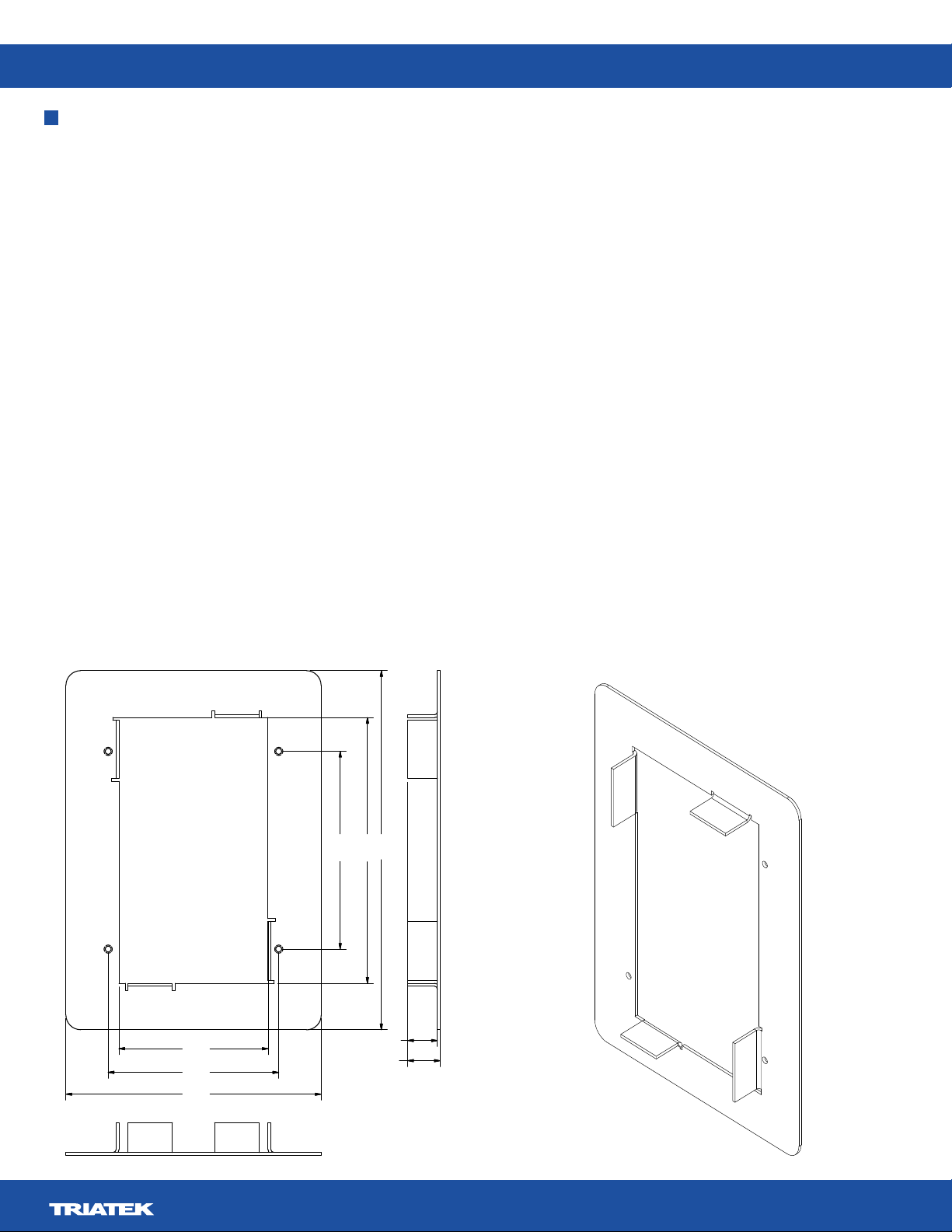
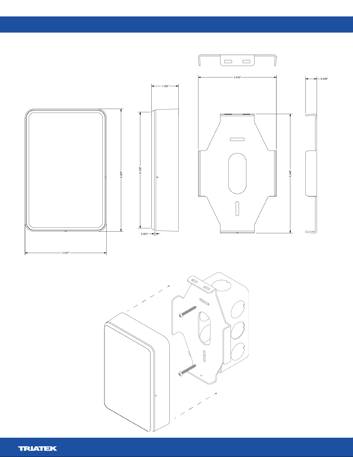
6.06in.
4.485in.
3.338in.
0.548 in.
0.5 in.
4.311 in.
2.519 in.
2.878 in.
(63.983 mm)
(73.101 mm)
(109.499 mm)
(12.07 mm)
(13.919 mm)
(84.785 mm)
(113.919 mm)
(153.924 mm)
• a drywall saw or an oscillating tool with a drywall saw blade
•
• a #2 Phillips head screwdriver
•
Note:
display to the wall.
1. Choose the location where you want to place the FMS-2000M Lite monitor.
2.
choose to use landscape orientation.
3. Mark both screw holes and the corners of the rectangular section.
4. Use a drywall saw or oscillating tool to cut out the entire rectangular section inside the marked opening and drill the screw holes.
5.
6.
7.
8.
to secure both the box and the bracket.
Note:
9. Connect the wires to the back of the monitor. For more information, refer to Figure 11.
10. Align the two slots on the back of the monitor with the tabs on the bracket, then swing the monitor towards the wall so that the
single tab on the bracket slots into the back of the monitor.
11.
Halo bezel lights up green to represent the current system status.
Installing the FMS-2000M Lite Thin Mount display for a retrot application

FMS-2000M Lite
LIT-12013692
10
Item Component
1 FMS-2000M Lite Critical Environment Monitor
2 Monitor bracket
3
4 Retrofit ring
5 Mounting screw
6 Set screw
FMS-2000M Lite
LIT-12013692
11
Use the rough-in box for new construction applications when the walls have not yet been installed.
• a drywall saw or an oscillating tool with a drywall saw blade
•
• a #2 Phillips head screwdriver
•
Note: If you want to install the FMS-2000M Lite in a new construction application, attach the rough-in box before the walls are installed.
You can then attach the display once the walls are in place.
1.
choose to use landscape orientation.
2. Mount the rough-in box to the side of a stud.
that you install later.
3.
4. If the 2-conductor power cable terminates at the monitor, pull the 2-conductor power cable through the opening in the rough-in box.
5.
precisely with the rough-in box.
6. Align the monitor’s mounting bracket to the four screw holes on the mounting tabs of the rough-in box. Use a #2 Phillips head
screwdriver to secure the bracket with the screws provided. Make sure the bracket is level.
Note:
7. Connect the wires to the back of the monitor. For more information, refer to Figure 11.
8. Align the two slots on the back of the monitor with the tabs on the bracket and swing the monitor towards the wall so that the single
tab on the bracket slots into the back of the monitor.
9.
drive the screw into the monitor until it engages with the tab on the bracket.
Safety Halo bezel lights up green to represent the current system status.
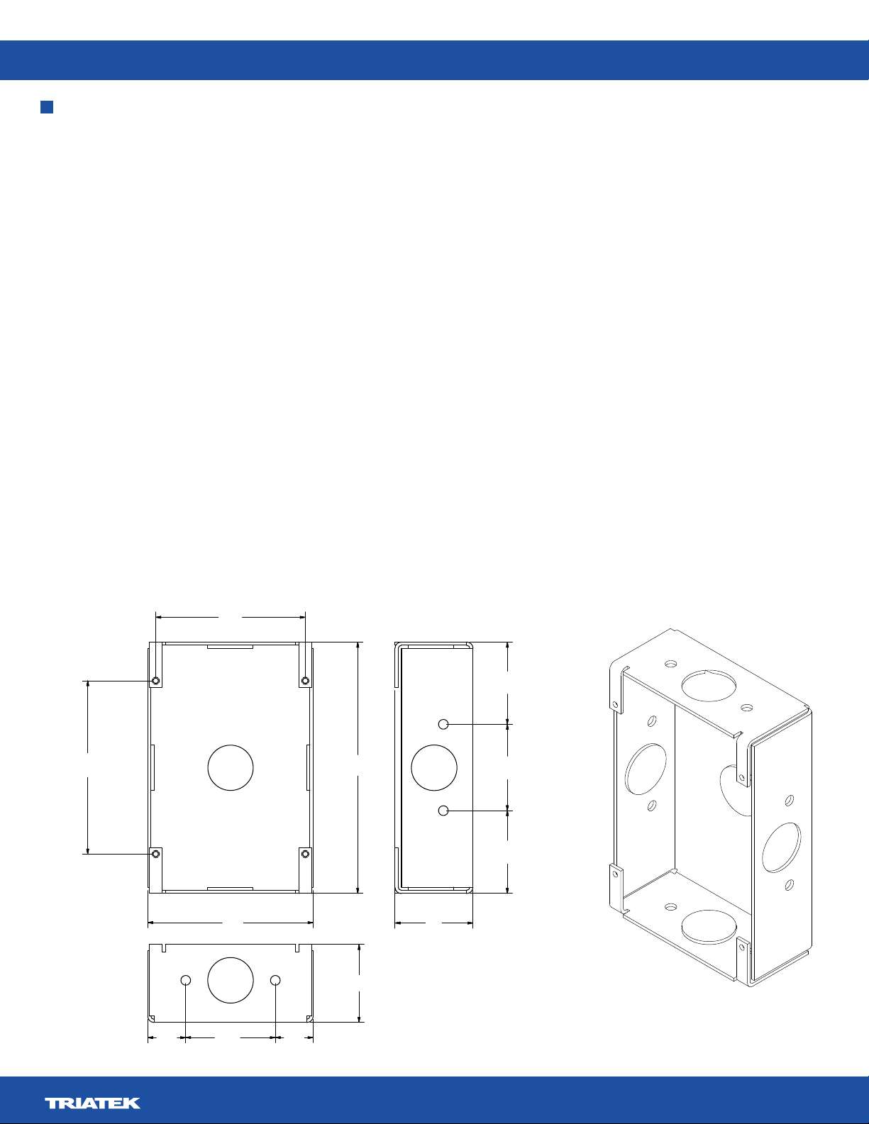
Installing the FMS-2000M Lite Thin Mount display for a new application
1.583in.
1.662in.
1.596in.
1.5 in.
3.18 in.
2.878 in.
3.338in.
4.84in.
1.5
in.
0.728in. 1.725 in. 0.728in.
(84.785 mm)
(122.94 mm)
(40.208 mm)
(42.215 mm)
(40.538 mm)
(73.101 mm)
(80.77 mm) (38.1 mm)
(18.491 mm) (43.815 mm) (18.491 mm)
(38.1 mm)

FMS-2000M Lite
LIT-12013692
12
Item Component
1 FMS-2000M Lite Critical Environment Monitor
2 Mounting bracket
3
4 Stud
5 Rough-in box
6 Mounting screw
7 Set screw
FMS-2000M Lite
LIT-12013692
13

FMS-2000M Lite
LIT-12013692
14
Number Description
1Surface mount display
2Existing wall box
3Mounting plate

FMS-2000M Lite
LIT-12013692
15
monitored spaces. Install the remote pressure sensor module in the wall facing the monitored space such as an isolation room. Install
positive pressure value indicates that the monitored space is positive with respect to the reference space. Choose a location that is
See Figure 8 for more
information.
•
• a #2 Phillips head screwdriver
• a drywall saw or an oscillating tool with a drywall saw blade
1.
1,000 ft.
2. Remove the sensor’s louvered cover plate and stainless steel backplate from the orange wall bracket.
3. Cut an opening in the wall of the monitored space for the orange low voltage mounting bracket and for the remote pressure sensor
4. Use the rotating clamps to secure the bracket to the wall safely.
5.
6. Pull the 4-conductor signal wire through the cut out.
7. Install the mounting bracket in the drywall opening and pull the 4-conductor signal cable through the mounting bracket.
8.
9.
as possible to prevent kinks.
10.
11. Screw the louvered cover plate to the front.
12. Apply thin silicone caulking around
the tube, between the stainless steel plate and the wall to seal against penetration.
13. Press the mounting plate into place. Allow the excess tube length to go into the wall space. Secure the mounting plate with the
screws and anchors.
14. Screw the louvered cover plate to the front.
Mounting the remote pressure sensor
FMS-2000M Lite
LIT-12013692
16
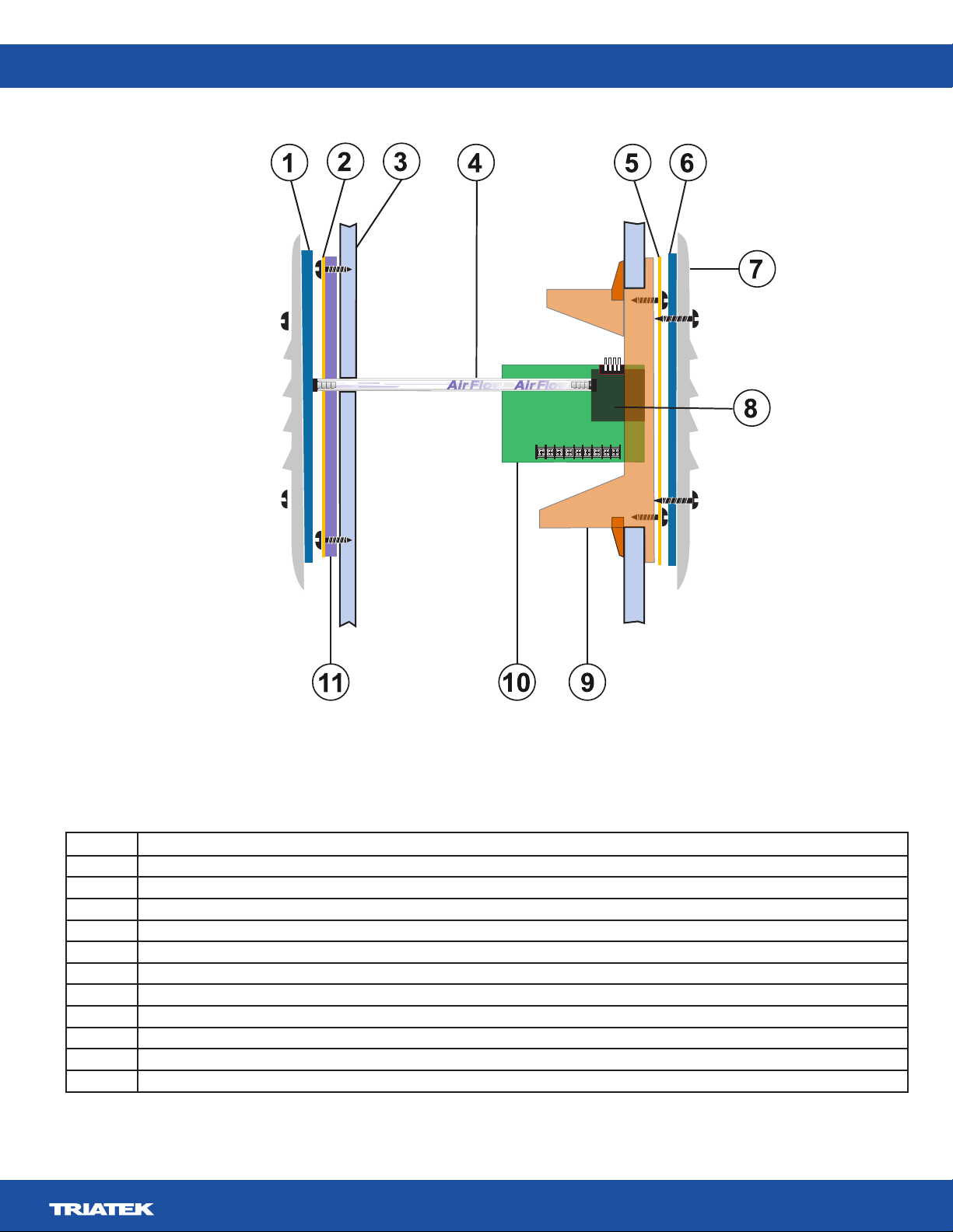
Monitored spaceReference space
Number Description
1
2 Stainless steel flow tube mounting plate
3
4 Flow tube
5 Stainless steel mounting plate
6
7 Louvered cover plate
8 Remote pressure sensor
9 Mounting bracket
10
11

FMS-2000M Lite
LIT-12013692
17
Wiring the system and BACnet MS/TP communications
Callout Component
1 DIP switch
2 Remote pressure sensor
3 Power supply
• Wiring one remote pressure sensor to the monitor
Note:
4 Supervisory device
5 FMS-2000M Lite Critical Environment Monitor
+
24V_IN
–
+
DSPLY
RS485
–
+
BACnet
MS/TP
–
REF
120 VAC 24 VAC
FMS-2000M Lite
LIT-12013692
18
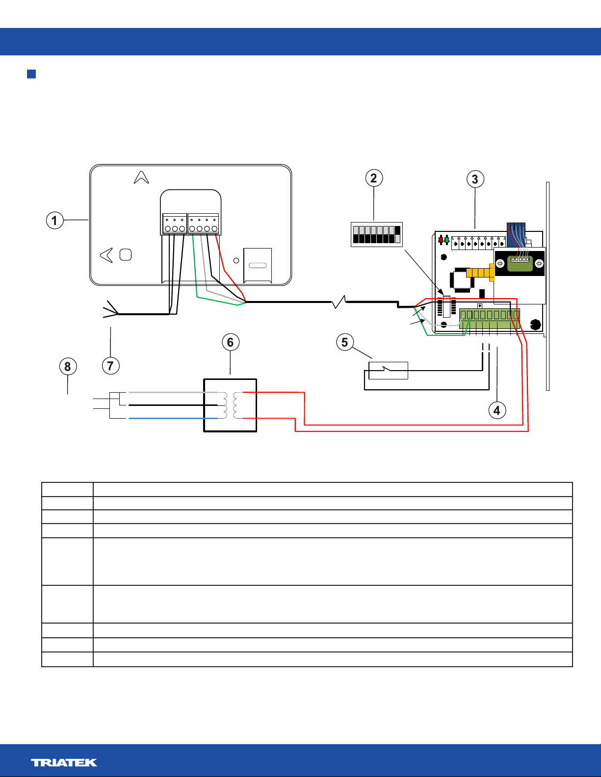
Wiring one remote pressure sensor to the monitor
Note: For optimum network communications, connect the reference signal (REF) to the COM terminal on the supervisory device’s FC
bus terminal block.
17
1
U2
33
49
75
1
CN1
S2
SW1
+Vin
-Vin
Io
+Vs
IN
GND
-
+
RS485
21
43
ADDR
6
JP4
LED1
LED2
RUN
PWR
JP5
CN3
5
JP2
24 VAC
Output
To BAS
network
-
+
Ref.
22 AWG stranded 3-wire
twisted pair, shielded
Supplied 10 � cable
Green
White
Black
Red
Green
White
Black
Red
}
Power input
P1
P2
COMMON
120 VAC input
240 VAC input
White
Black
Blue
+
-
+
-
+
-
REF
24V_IN
DSPLY
RS485
BACnet
MS/TP
Landscape
Portrait
120 VAC/240 VAC
60/50Hz input
Callout Component
1 FMS-2000M Lite monitor
2
3 Supplied remote pressure sensor
4 Io terminal
Note: A 4mA to 20mA signal is present at the sensor’s Io terminal which represents the monitored room pressure. You can use it to
5 Optional door switch
Note: Configure the door switch setting on the monitor. It can be normally closed or normally open.
6 Power supply
7
8 AC power input options
FMS-2000M Lite
LIT-12013692
19
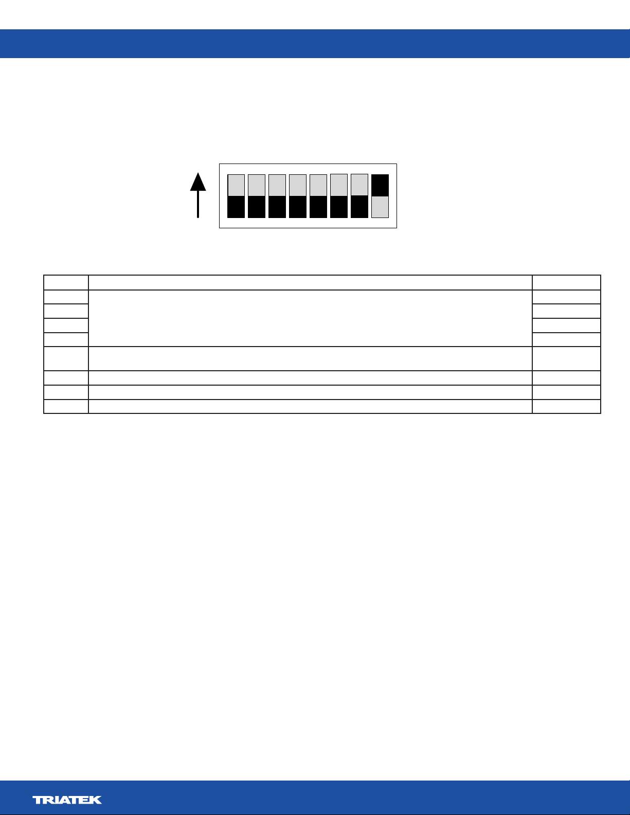
Switch Description Sensor 1
1
Sensor address
On
2 On
3 On
4 On
5
power to the sensor for the mode change to take effect.
On or off
6 Reserved
7 Reserved
8 Sensor communications termination Off
SW1
12345678
On
FMS-2000M Lite
LIT-12013692
20
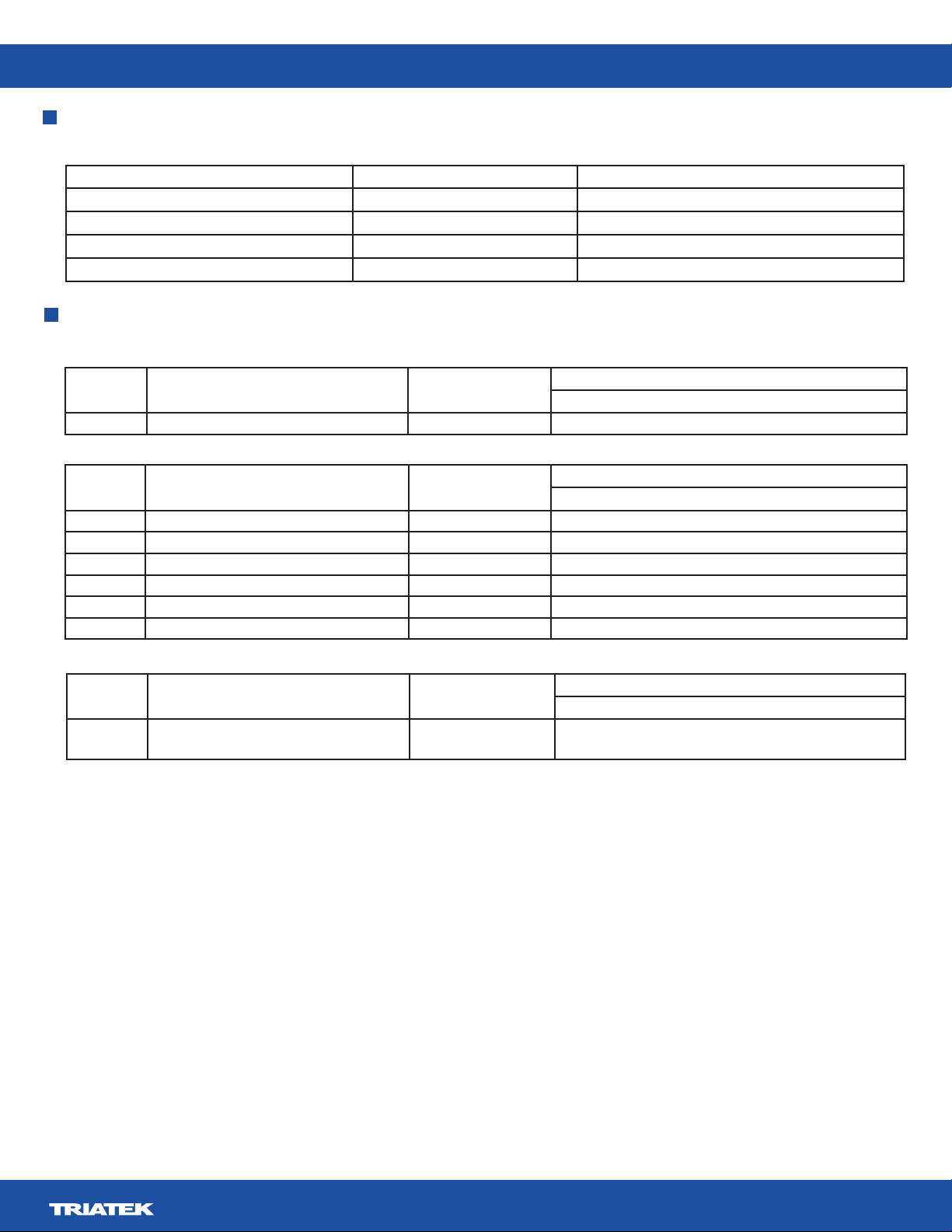
BMS integration
Conguring the display module settings
FMS-2000M Lite DIP switch position Demo mode Run mode
Position 1 On On
Position 2 On On
Position 3 Off On
Position 4 On Off
Objects Analog inputs Read/Write Availability of analog input objects
FMS2ML–BxR
AI-1 Analog input 1, differential pressure Read only Yes
Objects Analog values Read/Write Availability of analog value objects
FMS2ML–BxR
AV-1 Network Variable temperature 1 Read or write Yes
AV-2 Differential Pressure low alarm setpoint 1 Read or write Yes
AV-3 Differential Pressure low warning setpoint 1 Read or write Yes
AV-4 Differential Pressure high warning setpoint 1 Read or write Yes
AV-5 Differential Pressure high alarm setpoint 1 Read or write Yes
AV-6 Network Variable humidity 1 Read or write Yes
Objects Multistate value objects Read/Write Availability of multistate value objects
FMS2ML–BxR
MV-1 AI-1 Alarm Status
1 = positive, 2 = negative, 3 = neutral
Read only Yes
Table of contents
Other TRIATEK Monitor manuals


