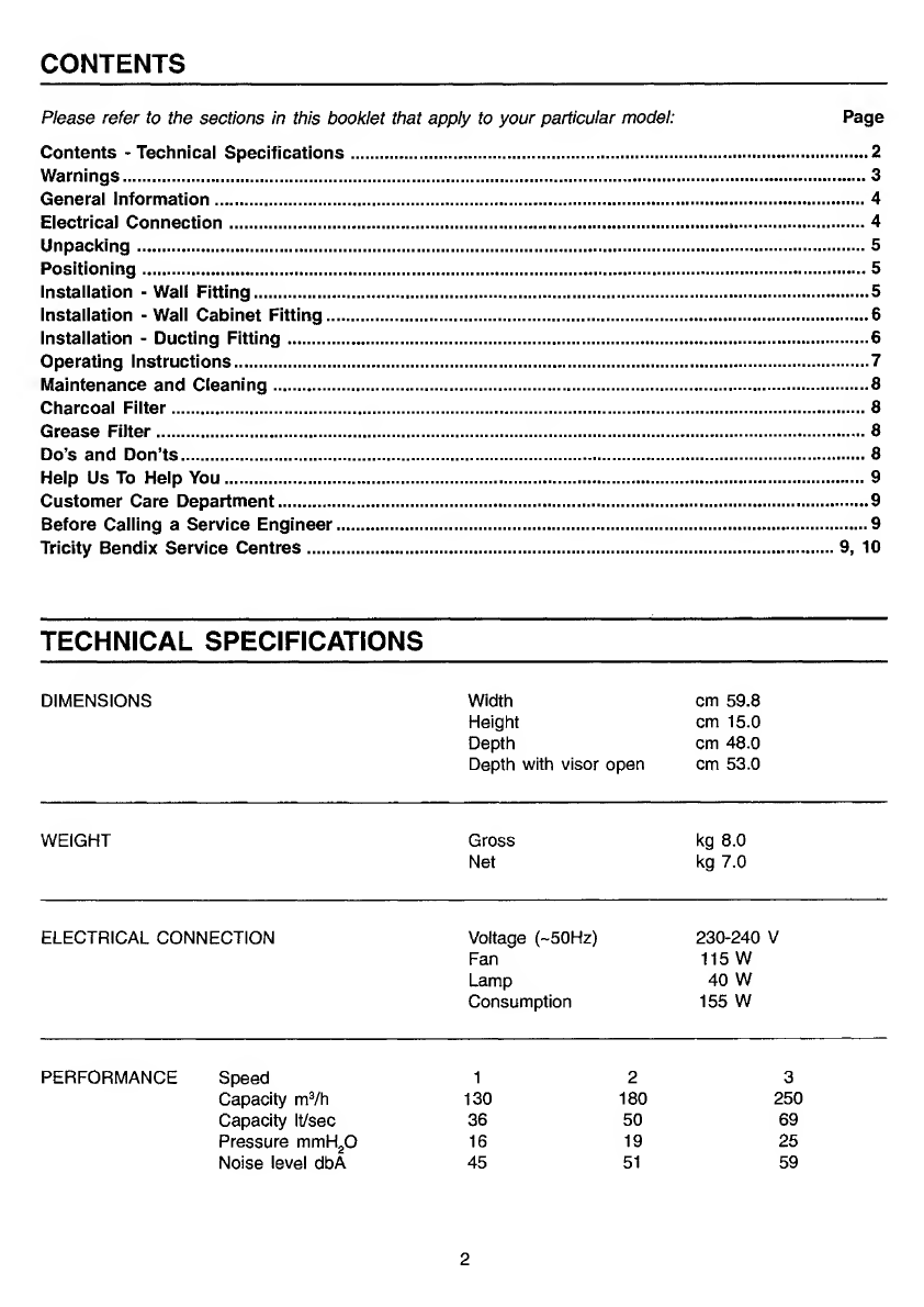
Tricity Bendix CH 605 Assembly instructions

TRIQTY
BE
NDIX
Better
Products.
Better
Value.
Visor
Cooker
Hood
-
CH
605
Operating
and
Installation
Instructions

CONTENTS
Please
refer
to
the
sections
in
this
booklet
that
apply
to
your
particular
model:
Page
Contents
-
Technical
Specifications.2
Warnings.3
General
information.4
Electrical
Connection.4
Unpacking.5
Positioning.5
Installation
-
Wall
Fitting.5
Installation
-
Wall
Cabinet
Fitting.6
Installation
-
Ducting
Fitting.6
Operating
Instructions.7
Maintenance
and
Cleaning.8
Charcoal
Filter.8
Grease
Filter.8
Do’s
and
Don’ts.8
Help
Us
To
Help
You.9
Customer
Care
Department.9
Before
Calling
a
Service
Engineer.9
Tricity
Bendix
Service
Centres.9,
10
TECHNICAL
SPECIFICATIONS
DIMENSIONS
Width
cm
59.8
Height
cm
15.0
Depth
cm
48.0
Depth
with
visor
open
cm
53.0
WEIGHT
Gross
Net
kg
8.0
kg
7.0
ELECTRICAL
CONNECTION
Voltage
(--50Hz)
230-240
V
Fan
115
W
Lamp
40
W
Consumption
155
W
PERFORMANCE
Speed
1
2
3
Capacity
m^/h
130
180
250
Capacity
It/sec
36
50
69
Pressure
mmH^O
16
19
25
Noise
level
dbA
45
51
59
2

WARNINGS
It
is
most
important
that
this
instruction
book
should
be
retained
with
the
appliance
for
future
reference.
Should
the
appliance
be
sold
or
transferred
to
another
owner,
or
should
you
move
house
and
leave
the
appliance
al¬
ways
ensure
that
the
book
is
supplied
with
the
appliance
in
order
that
the
new
owner
can
be
acquainted
with
the
functioning
of
the
appliance
and
the
relevant
warnings.
Please
ensure
that
you
have
read
the
whole
instruc¬
tion
book
before
using
the
appliance
and
that
you
follow
the
recommendations
given.
These
warnings
are
provided
in
the
interest
of
safety.
They
must
be
read
carefully
before
installing
or
using
this
appliance.
This
appliance
is
designed
to
be
operated
by
adults.
Children
should
not
be
allowed
to
tamper
with
the
controls
or
play
with
the
product.
It
is
dangerous
to
alter
the
specifications
or
modify
the
product
in
any
way.
Any
installation
work
must
be
undertaken
by
a
qualified
electrician
or
a
competent
person.
This
product
should
be
serviced
by
an
author¬
ised
Tricity
Bendix
Service
Centre,
and
only
genuine
Tricity
Bendix
spare
parts
should
be
used.
Never
leave
frying
pans
unattended
during
use
as
overheated
fats
and
oils
may
catch
fire.
Never
do
flambe
cooking
under
this
cooker
hood.
It
is
a
possible
fire
hazard
if
the
grease
and
charcoal
filter
are
not
replaced
as
recommended.
When
used
in
the
extraction
mode
the
cooker
hood
must
not
be
connected
to
a
flue
which
is
used
for
exhausting
fumes
from
appliances
sup¬
plied
with
energy
other
than
electric
such
as
a
central
heating
flue
or
water
heater.
If
the
room
where
the
cooker
hood
is
to
be
used
contains
a
fuel
burning
appliance
such
as
a
central
heating
boiler
then
its
flue
must
be
of
the
room
sealed
or
balanced
flue
type.
If
other
types
of
flue
or
appliances
are
fitted
ensure
that
there
is
an
adequate
supply
of
air
to
the
room.
WARNINGS
Cont'd
All
installations
must
comply
with
the
local
au¬
thorities
requirements
for
the
discharge
of
ex¬
haust
air.
If
the
hood
is
installed
for
use
above
a
gas
ap¬
pliance
then
the
provision
for
ventilation
must
be
in
accordance
with
the
Gas
Safety
(Installation
&
Use)
Regulations
1994
No.
1886
and
the
rel¬
evant
building
regulations.
Details
are
contained
in
the
following
British
Standard
Codes
of
Practise
BS.6172
BS.5440
and
BS.6891
Current
Edition.
The
fan
motor
of
this
cooker
hood
incorporates
a
thermal
cut-out
device
which
will
operate
if
the
cooker
hood
is
installed
below
the
minimum
height
recommended
in
this
booklet,
or
if
the
motor
becomes
overheated.
If
the
cut-out
device
is
activated,
switch
off
the
fan
motor
and
allow
the
cooker
hood
to
cool.
The
cut-out
device
will
reset
itself
when
the
fan
motor
has
cooled
sig¬
nificantly.
This
cooker
hood
has
been
designed
for
in-
staiiation
over
an
eiectric
hotplate
with
a
maximum
input
of
7Kw
or
a
gas
hotpiate
with
a
maximum
input
of
10Kw
when
fitted
in
accordance
with
the
heights
recommended
in
this
booklet.
Under
no
circumstances
should
you
attempt
to
repair
the
appliance
yourself.
Repairs
carried
out
by
an
inexperienced
person
may
cause
injury
or
more
serious
malfunctioning.
Refer
to
your
local
Tricity
Bendix
Service
Centre.
Always
insist
on
genuine
Tricity
Bendix
spare
parts.
3

GENERAL
INFORMATION
This
instruction
book
,
applies
to
the
following
models:
Tricity
Bendix
CH605B
Brown
60cm
Tricity
Bendix
CH605W
White
60cm
This
cooker
hood
is
guaranteed
and
will
give
lasting
service.
The
guarantee
is
only
applicable
If
the
hood
has
been
installed
in
accordance
with
the
installation
instructions
detailed
in
this
book¬
let.
This
cooker
hood
has
been
designed
for
use
fixed
beneath
a
wall
cabinet
or
directly
onto
the
wall
using
the
special
brackets
supplied
and
should
be
installed
in
accordance
with
the
fol¬
lowing
fitting
instructions.
The
hood
can
be
used
to
extract
odours
to
the
outside
or
to
recirculate
the
air
within
the
kitchen
after
passing
the
contaminated
air
through
a
(optional)
cleansing
charcoal
filter.
The
hood
is
convertible
to
either
function
by
the
movement
of
a
change-over
slider
control.
This
enables
the
cooker
hood
when
installed
in
the
extraction
mode,
to
be
converted
to
recirculation
during
the
winter
months.
The
installation
instructions
which
follow
give
instructions
on
how
and
where
this
hood
may
be
fitted.
If
already
installed
check
with
the
installer
that
all
the
requirements
have
been
met.
If
not
then
draw
these
to
the
attention
of
the
installer
who
should
be
a
qualified
electrician
or
a
com¬
petent
person.
Tricity
Bendix
disclaims
all
liability
for
any
dam¬
age
or
injury
caused
as
a
result
of
not
following
the
instructions
contained
in
the
following
text.
ELECTRICAL
CONNECTION
Before
connecting
to
the
mains
supply
ensure
that
the
mains
voltage
corresponds
to
the
volt¬
age
on
the
rating
plate
inside
the
cooker
hood.
WARNING:
THIS
APPLIANCE
MUST
BE
EARTHED.
This
appliance
is
fitted
with
a
3
core
mains
sup¬
ply
cable
and
should
be
permanently
connected
to
the
electricity
supply
via
a
double-pole
switch
having
3mm
minimum
contact
gap
on
each
pole.
A
Switched
Fuse
Connection
Unit
to
BS.1363
Part
4,
is
a
recommended
mains
supply
connec¬
tion
accessory
to
ensure
compliance
with
the
Safety
Requirements
applicable
to
fixed
wiring
instructions.
Any
permanent
electrical
installation
must
com¬
ply
with
the
latest
I.E.E.
Regulations
and
local
Electricity
Board
regulations.
For
your
own
safety
this
should
be
undertaken
by
a
qualified
electri¬
cian
e.g.
your
local
Electricity
Board,
or
a
con¬
tractor
who
is
on
the
roll
of
the
National
Inspec¬
tion
Council
for
Electrical
Installation
Contracting
(NICEIC).
WARNING:
INCORRECT
INSTALLATION
COULD
AFFECT
THE
SAFETY
OF
THIS
COOKER
HOOD.
DISCONNECT
THE
HOOD
FROM
THE
MAINS
SUPPLY
BEFORE
CARRYING
OUT
ANY
KIND
OF
MAINTENANCE
OR
CLEANING.
This
appliance
conforms
to
BS.800:1988
and
EEC
Directive
No
87/308
regarding
suppression
of
radio
and
television
interference.
4

INSTALLATION
Unpacking
Care
should
be
taken
when
unpacking
the
cooker
hood
to
ensure
that
the
fixing
kit,
ducting
spigot,
blanking
plate
and
literature
pack
are
retained
with
the
hood.
The
fixing
kit
comprises:
1-
fixing
template
2-
wall
fixing
brackets
4-
plastic
rawl
plugs
4-
fixing
screws
2-
shakeproof
washers
2-
security
nuts
Positioning
When
installed
above
an
electric
cooking
appli¬
ance
the
minimum
distance
between
the
surface
of
the
hob
elements
and
the
lower
grille
of
the
cooker
hood
must
be
65cm
(25
1/2").
When
installed
above
a
gas
cooking
appliance
the
minimum
distance
between
the
surface
of
the
hob
pan
supports
and
the
lower
grille
of
the
cooker
hood
must
be
70cm
(27
1/2").
When
installed
above
a
cooking
appliance
with
a
high
level
grill
the
minimum
distance
between
the
upper
surface
of
the
grill
and
the
lower
grille
of
the
cooker
hood
must
be
45cm
(17
3/4").
The
distance
between
the
underside
of
adjoining
wall
cabinets
and
the
worktop
must
not
be
less
than
40cm
(15
3/4").
Wall
Fitting
The
cooker
hood
may
be
fitted
to
any
rigid
vertical
surface.
All
the
fittings
supplied
are
to
be
found
in
a
polythene
bag
inside
the
carton.
IMPORTANT:
Before
installation
check
the
wall
to
which
the
cooker
hood
is
to
be
fitted
for
electric
cables,
water
pipes
or
gas
pipes
before
drilling.
If
it
is
necessary
to
fix
the
hood
to
a
hollow
construction
plaster
or
partition
board
structure
then
it
must
be
sufficiently
reinforced
to
be
quite
rigid
in
the
area
of
the
cooker
hood
mounting
brackets.
The
hood
must
not
be
fitted
using
the
key
hole
fixing
points
but
with
the
special
brack¬
ets
supplied.
INSTALLATION
Cont'd
Use
the
paper
template
provided
to
mark
the
hole
positions
on
the
wall
for
the
bracket
fixing
screws.
Check
the
hole
distances
are
correct
with
a
tape
measure
as
stated
on
the
template.
At
this
stage
it
is
important
to
allow
15mm
(1/2")
clear
space
above
the
cooker
hood
to
enable
it
to
be
hooked
onto
the
brackets
and
for
subse¬
quent
removal
for
decorating
or
servicing.
When
drilling
the
holes
for
the
wall
fixing
brack¬
ets
care
must
be
taken
to
ensure
that
they
are
quite
level
as
there
is
minimal
vertical
height
adjustment
of
the
fixing
brackets.
The
brackets
should
be
fitted
with
the
round
end
at
the
bottom
using
the
plastic
rawl
plugs
and
screws
provided.
If
the
brackets
are
to
be
fitted
to
a
hollow
plaster
or
partition
board
structure
then
the
plastic
rawl
plugs
provided
should
not
be
used.
Once
the
brackets
are
secured
lift
the
hood
squarely
to
the
wall
slightly
higher
than
the
brackets
and
lower
the
cooker
hood
until
the
cooker
hood
locates
onto
the
two
brackets.
Ensure
that
the
cooker
hood
is
correctly
located
before
letting
go.
Access
to
the
two
wall
levelling
screws
and
the
security
fixing
system
will
require
the
removal
of
the
lower
inlet
grille
that
supports
the
grease
mat
filter.
To
remove
the
lower
grille
press
inwardly
on
the
two
slide
catches
located
towards
either
side
of
the
grille
near
the
front
and
the
grille
will
open
from
the
front.
The
grille
pivots
at
the
rear.
Slide
the
right
edge
of
the
grille
forward
until
it
clears
the
guide
and
then
unhook
the
left
hinge
pin.
Care
should
be
taken
to
fully
support
the
grille
when
removing
it
from
the
guides.
The
two
wall
levelling
screws
will
be
visible
toward
either
end
of
the
back
panel,
when
the
grille
has
been
removed.
Turn
the
screws
clock¬
wise
to
lift
the
front
edge
of
the
hood
and
use
a
spirit
level
to
check
the
hood
is
positioned
a1
right
angles
to
the
wall
before
fitting
the
security
system.
5

INSTALLATION
Cont'd
The
wall
brackets
have
two
studs
and
when
the
cooker
hood
is
hung
onto
the
brackets
the
studs
project
through
the
two
holes
above
the
levelling
screws.
When
the
hood
is
level
fit
the
two
shakeproof
washers
and
nuts
supplied
to
fully
secure
the
cooker
hood.
Wall
Cabinet
Fitting
Before
fitting
the
cooker
hood
beneath
any
type
of
wall
cabinet
ensure
it
is
firmly
fixed
to
the
wall
in
accordance
with
the
manufacturers
instruc¬
tions.
Use
the
paper
template
provided
to
mark
the
hole
positions
on
the
underside
of
the
cabinet.
When
marking
the
underside
of
the
cabinet
the
front
edge
of
the
template
must
be
aligned
with
the
front
edge
of
the
cabinet
carcase.
Check
the
distances
of
the
holes
are
correct
with
a
tape
measure
as
stated
on
the
template.
The
four
holes
are
5mm
(1/4")
dia.
A
pad
saw
or
similar
cutter
will
be
required
to
cut
the
circular
hole
for
the
ducting
spigot
if
it
is
to
be
used.
Insert
the
fixing
screws
through
the
holes
from
inside
the
cabinet.
Supporting
the
cooker
hood
tighten
each
screw
about
half
way
to
ensure
that
the
cooker
hood
is
correctly
positioned
before
fully
tightening
the
screws.
DUCTING
FITTING
If
the
hood
is
to
be
ducted
to
the
outside
then
the
blanking
plate
supplied
must
be
fitted
in
the
aperture
that
will
not
be
used.
Fit
the
ducting
spigot
into
the
selected
aperture
and
make
an
air
tight
connection.
The
ducting
used
must
be
100mm
(4")
diameter,
manufactured
from
fire
retardent
material
con¬
forming
to
the
relevant
British
Standard
or
DIN
4102-B1.
Where
flexible
ducting
is
fitted
it
should
not
be
turned
through
very
tight
bends
as
this
could
impair
the
performance
of
the
hood.
To
fit
the
ducting
spigot
and
blanking
plate
align
the
inter-locking
lugs
on
the
fitting
with
the
re¬
cesses
in
the
aperture
and
insert
turning
clock¬
wise
to
lock
the
spigot
and
blanking
plate
into
position.
(The
maximum
length
of
ducting
including
one
90
Degree
bend
should
be
3
metres,
to
be
re¬
duced
by
1
metre
for
each
90°
bend
installed
in
the
duct
run).
When
the
ducting
mode
is
selected
the
op¬
tional
charcoal
filter
is
not
required.
6

OPERATING
INSTRUCTIONS
OPERATING
INSTRUCTIONS
Confd
The
cooker
hood
functions
are
controlled
by
two
slide
switches
and
a
change-over
slider
control.
The
two
slide
switches,
which
are
located
on
the
right
hand
side
in
the
front
fascia
panel,
control
the
fan
speed
and
worktop
illumination.
The
change-over
slider
control
is
located
inside
the
cooker
hood
behind
the
inlet
grille
immedi¬
ately
in
front
of
the
lamp
assembly.
Ensure
the
hood
is
plugged
in,
or
wired
in
and
the
power
supply
is
switched
on.
The
switch
marked
with
the
lamp
symbol
and
numbered
0-1
controls
the
worktop
lighting.
Po¬
sition
-1
indicates
the
light
is
operating.
The
switch
marked
with
the
fan
symbol
and
numbered
0-1-2-3
controls
the
fan
speed,
-1
Low,
-2
Normal
and
-3
Boost.
Position
-1
Should
be
selected
when
sim¬
mering
or
when
using
one
pan.
Position
-2
Should
be
selected
for
normal
cooking
up
to
four
pans.
Position
-3
Should
be
selected
when
fry¬
ing
or
cooking
food
with
strong
odour.
In
the
recirculation
position,
slider
towards
the
charcoal
filter,
air
enters
the
cooker
hood,
passes
through
the
grease
and
charcoal
filter
and
out
through
the
holes
in
front
of
the
casing
top
panel.
To
convert
the
hood
from
extraction
to
recircu¬
lation
open
the
metal
inlet
grille
and
slide
the
change-over
control
to
the
right.
Remove
the
thumb
screw
from
the
motor
support.
Take
the
charcoal
filter
and
place
it
over
the
motor
sup¬
port
and
secure
by
passing
the
thumb
screw
through
the
hole
in
the
filter
and
into
the
capti¬
vated
nut
in
the
centre
of
the
motor
support.
In
the
ducting
position,
with
the
slider
away
from
the
charcoal
filter,
the
air
passes
through
the
grease
filter
and
out
through
ducting
to
the
at¬
mosphere.
When
the
ducting
position
is
selected,
the
(optional)
charcoal
filter
is
not
required.
NOTE:
The
hood
is
more
effective
when
used
in
the
extraction
(ducting)
mode,
therefore
this
position
should
be
selected
during
the
warmer
months
of
the
year
when
no
room
heating
is
required.
When
the
room
is
being
heated
if
the
recirculation
position
is
selected
heat
will
not
be
wasted.
To
obtain
the
best
performance
it
is
advisable
to
switch
on
the
cooker
hood
a
few
minutes
before
you
start
cooking
and
leave
it
running
for
15
minutes
after
finishing.
7

MAINTENANCE
DISCONNECT
THE
HOOD
FROM
THE
MAINS
SUPPLY
BEFORE
CARRYING
OUT
ANY
KIND
OF
MAINTENANCE
OR
CLEANING.
Worktop
Lighting
If
a
lamp
fails
to
function
at
any
time
first
check
that
it
is
fully
screwed
into
the
holder.
When
changing
the
lamp
an
identical
replace¬
ment
must
be
fitted
to
ensure
the
safe
working
of
the
cooker
hood.
Replacement
lamps
are
specified
230-240Volts
40Watt
clear
cylindrical,
candle,
or
tulip
shape
with
small
Edison
(El4)
screw
thread
cap.
Cleaning
For
your
own
safety
and
in
the
interests
of
hy¬
giene
your
cooker
hood
needs
to
be
kept
clean.
A
build
up
of
grease
or
fat
from
cooking
could
cause
a
fire
hazard.
Never
use
excessive
amounts
of
water
when
cleaning
particularly
around
the
control
panel
area.
The
metal
casing,
lower
grille
assembly
and
glass
visor
should
be
cleaned
at
least
once
a
month
to
keep
it
looking
like
new.
Wipe
over
the
cooker
hood
with
a
soft
cloth
wrung
out
in
hot
water
and
containing
a
mild
household
cleaner
and
dry
with
a
soft
cloth.Always
wear
protective
gloves
when
cleaning
the
hood.
NOTE:
Never
use
scouring
pads
or
abrasive
cleaners
as
they
might
scratch
or
damage
the
surface.
Charcoal
Filter
The
charcoal
filter
cannot
be
cleaned.
It
should
be
replaced
at
least
once
every
three
months
or
more
frequently
if
the
cooker
hood
is
used
for
more
than
three
hours
a
day.
Grease
Filter
The
grease
filter
is
fitted
to
absorb
grease
and
dust
during
cooking
to
help
keep
the
appliance
clean
inside.
MAINTENANCE
Cont'd
Synthetic
Grease
Filter
The
neutral
syntetic
grease
filter
cannot
be
cleaned.
It
should
not
be
washed.
The
filter
should
be
replaced
at
least
once
every
three
months
or
more
frequently
if
the
cooker
hood
is
used
for
more
than
three
hours
a
day.
IMPORTANT:
There
could
be
a
possible
fire
hazard
if
the
grease
and
charcoal
filters
are
not
replaced
according
to
these
instructions.
For
replacement
filters
please
use
the
order
form
enclosed.
Do‘s
and
Don'ts
Do’s
Do
have
the
visor
open
when
using
the
hob
even
if
the
fan
on
the
hood
is
not
switched
on.
Do
take
extra
care
when
frying.
Do
keep
heating
areas
on
your
hob
covered
over
with
pots
and
pans
when
using
the
hob
and
cooker
hood
simultaneously.
Don’ts
Don’t
leave
naked
flames
under
the
hood.
Don’t
leave
frying
pans
unattended
during
use
as
over
heated
fats
and
oils
may
catch
fire.
Don’t
do
flambe
cooking
under
this
cooker
hood.
8

TRYCITY
BENDIX
SERVICE
CENTRES
ABERDEEN
AB
01224
696569
Tricity
Bendix
After
Sales
Service
Northeast
Appliance
Service
8
Cornhill
Arcade
Aberdeen
AB2
5UT
HAVERFORDWEST
SA
33-39.
41-44,
61-73
01437
710914
Tricity
Bendix
After
Sales
Service
•>
C
Butherway
1
Church
Road
Roch
Haverfordwest
Dyfed
Wales
SA62
6AG
ARGYLLE
PA24'61
01505
321316
Tricity
Bendix
After
Sales
Service
Briar
Hill
7
Hilt
Street
Djnoon
PA23
7AL
HEREFORD
HR
1-9.
LD1-8.
SY7,
SY18,
NP
5,
NP7.8
01432
340334
Tricity
Bendix
After
Sales
Service
Domestic
Repair
Centre
Unit
3
Bank
Buildings
Cattle
Market
Hereford
HR49HX
BARNSTAPLE
EX18-23,
31'39
01271
328826
Tricity
Bendix
After
Sales
Service
McBain
Refrigeration
P.O.
Box
12
Barnstaple.
North
Devon
EX31
2YB
HULL
YO
4,
11-18,
25
HU
1-19
DN14
01482
585678
Tricity
Bendix
After
Sales
Service
John
Sizer
Unit
1
Boulevard
Unit
Factory
Estate
Hull
HU34AY
BORDERS
TD
01573224411
Tricity
Bendix
After
Sales
Service
James
Stewart
&
Son
2-8
Wood
Market
Kelso
Borders
TD57AX
INVERNESS
IV
1-28,
30-36,
40-49,
51-56
PH
19-26,
30-44
KW1-14
01463
792952
Tricity
Bendix
After
Sales
Service
Highland
Appliances
Unit
3B3
Smlthton
Industrial
Estate
Smithton
Inverness
IV1
2PD
BRISTOL
BS
SP
TA
0117
921
1876
Tricity
Bendix
After
Sales
Service
P.O.
Box
372
Bristol
BS99
1UD
ISLE
OF
WIGHT
PO
30-41
01983
872552
Tricity
Bendix
After
Sales
Service
Wyatts
Electrical
Service
4
Forelands
Road
Be
mb
ridge
Isle
of
Wight
P035
5XW
CANVEY
E.
EC,
EN,
N,
NW.W,
WC
AL,
CB.
HA,
HP.
LU.
MK,
SG
UB.WD,
PE16*19
CM,
CO.
iG.
RM,
SS
PE14,
15.17.
34,38
IP.
NR,
PE30-33.
PE35-37
0181
443
3464
0181
965
9699
0161
965
9699
01266
694144
01266
694144
01603
667017
01603
667017
01603
667017
01603
667017
Tricity
Bendix
After
Sales
Service
2-4
Sandhurst
Kings
Road
Canvey
island
SS8
OQY
JERSEY
JE
01534
505050
Jersey
Electricity
Company
POBOX45
Oueens
Road
St
Helier
Jersey
Channel
Islands
JE4
8NY
CARDIFF
CF,NP1-4.
6,
9*44
SA1-18,
21-32
01222
460131
Tricity
Bendix
After
Sales
Service
Guardian
Industrial
Estate
Clydesmuir
Road
Tremorla
Cardiff
CF2
2QS
LAMPETER
SA
19.
20.
40,
45-48
SY
23,
24,
25
01570
423020
Tricity
Bendix
After
Sales
Service
Lampeter
Domestic
Appliance
Services
Unit
16
Lampeter
Industrial
Estate
Lampeter
Dyfed
SA48
70Y
CUMBRIA
CA
01226
594747
Tricity
Bendix
After
Sales
Service
ET.B.
Services
Carlisle
Enterprise
Centre
James
Street^
Carlisle
CA2
SAP
Tricity
Bendix
After
Sales
Service
Allan
Crossan
(Service)
93
Irish
Street
Dumfries
Scotland
DG12PQ
DUMFRIES
A
galloway
DG1-14
01387
69694
LANCASTER
LA
1-23
01772
316175
Tricity
Bendix
After
Sales
Service
NL
Services
Unit
333
Banglet
Road
Walton
Summit
Bamber
Bridge
Preston
Lancashire
PR5
8AR
DUNDEE
DDl-14
PH8-18
01250
876285
Tricity
Bendix
After
Sales
Service
1
Brogan
Domestic
Caimleigh
Dunkeld
Road
Blairgowrie
Perthshire
PH106RT
LEEDS
BD.
DN1-7,
10-12,
HD,
HG.
HX.
LS.
S.
WF,
Y01-3.
5-8,
DE.
NG1-22.
25
01132608511
Tricity
Bendix
After
Sales
Service
64-66
Cross
Gates
Road
Leeds
LS15
7NN
LINCOLN
DN21
Subcodes
1.2.5
only
LN1.2.
4.
5,6
LN3
Subcodes
4
&
5
only
LN8-10
NG23.
24.
31
-34
PEI-13.
20-25
01522
514603
Tricity
Bendix
After
Safes
Seivice
GLASGOW
EH.
FK.G,
KA.
KY1-16.
ML.
PA1-23.
PHI-7,
ZE
0141
647
4381
Tricity
Bendix
After
Sales
Service
20
Cunningham
Road
Clyde
Estate
Rutherglen
Glasgow
Q731PP
Unit
8
Stonefield
Park
Clifton
Street
Lincoln
LN5
8AA
NEWTON
ABBOT
EX1-17
PL1-9.16.19.
20.
21
TQ
01626
65909
Tricity
Bendix
After
Sales
GUERNSEY
GU
01481
46931
Guernsey
Electricity
POBox4
Vale
Guernsey
Channel
Islands
South
West
Domestic
Services
Unit
2
Zealley
industrial
Estate
Kingsteignton
Newton
Abbot
South
Devon
T012
3SJ

HELP
US
TO
HELP
YOU
Please
determine
your
type
of
enquiry
before
writing
or
telephoning.
SERVICE
In
the
event
of
your
appliance
requiring
service,
Tricity
Bendix
have
an
arrangement
with
Electrolux
Group
Service.
Before
calling
out
an
engineer,
please
ensure
you
have
read
the
details
under
the
heading
‘Before
Calling
a
Service
Engineer’
and
have
the
model
number
and
purchase
date
to
hand.
The
telephone
number
and
address
for
service
is
detailed
on
the
list
headed
‘Tricity
Bendix
Service
Centres’.
PLEASE
NOTE
that
all
enquiries
concerning
service
should
be
addressed
to
your
local
Cus¬
tomer
Service
Centre.
CUSTOMER
CARE
DEPARTMENT
FOR
GENERAL
ENQUIRIES
concerning
your
Tricity
Bendix
appliance,
or
further
information
on
Cookers,
Cooker
Hoods,
Microwave
Ovens,
Refrigeration
or
Home
Laundry
equipment,
you
are
invited
to
contact
our
Customer
Care
De¬
partment.
Do
not
hesitate
to
contact
us
by
letter
or
tel¬
ephone
as
follows;
Customer
Care
Department
Tricity
Bendix
99
Oakley
Road
Luton
Bedfordshire
LU4
9QQ
Telephone:
(01582)
585858
BEFORE
CALLING
A
SERVICE
ENGINEER
We
strongly
recommend
that
you
carry
out
the
following
checks
on
your
appliance
before
call¬
ing
a
Service
Engineer,
it
may
be
that
the
prob¬
lem
is
a
simple
one,
which
you
can
solve
your¬
self
without
the
expense
of
a
Service
call.
If
our
Service
Engineer
finds
that
the
problem
is
listed
below
you
will
be
charged
for
the
call
whether
or
not
the
appliance
is
under
guarantee:
'
-
Make
sure
the
appliance
is
properly
wired
in
and
that
the
Connection
Unit
is
switched
"ON”.
-
Check
there
is
power
to
the
Connection
Unit.
-
Check
the
fuse
in
the
Connection
Unit.
-
Check
the
mains
fuse.
TRYCITY
BENDIX
SERVICE
CENTRES
NORTH
WALES
LL
01745
591616
01745
590096
Tricity
Bendix
After
Sales
Service
QMS
(Cymru)
Unit
2
Coed
-
Parc
Abergele
Road
Rhuddlan
Clwyd
Wales
LL18
5UG
NORTHERN
DLTS
DHY021.
22
01325
301400
Tricity
Bendix
After
Sales
DH
NE
$R
0191
493
2025
Service
FY
PR
WN
BB
BL
M
01282
774621
PO
Box
40
OL
SK
0151
254
1724
Preston
Road
CHCHLWA
0151
254
1724
Aycliffe
Industrial
Estate
Newton
Aycliffe
Co
Durham
DL5
6XA
NORTHERN
IRELAND
EAST
0T1-3O,
36-57,
63-67
01232
746591
Tricity
Bendix
After
Sales
Service
Unit
C3
Edenderry
Industrial
Estate
326
Crumlin
Road
Belfast
8T14
7EE
NORTHERN
BT31-35
01861
510400
Tricity
Bendix
After
Sales
IRELAND
WEST
BT60-62
BT68-32
BT92-94
Sen/ice
G
&
0
(Armagh)
Service
Owenmore
House
Kilwee
Business
Park
Upper
Ounmurray
Lane
Belfast
BT17
0HD
NUNEATON
B
DY
ST
TF
0121
358
7076
Tricity
Bendix
After
Sales
WR
WSWV
0121
358
5051
Service
GLNN
OX
SN
01993
704411
Unit
23-24
Alliance
Business
Park
CV
LEI
5
01203
354424
Townsend
Drive
or
0116251
5131
Nuneaton
Warwickshire
evil
6RX
REDRUTH
TR1-20,
26.
27
PL10-15.
17.
18,
22-35
01209
314407
Tricity
Bendix
After
Sales
Service
Cornwall
Domestic
Sen,rice
Unit
7D
Pool
Industrial
Estate
Druids
Road
Redruth
Cornwall
TR15
3QW
SHREWSBURY
SY1-6
SY8-17
SY19-22
01743
450279
Tricity
Bendix
After
Sales
Service
BLI
Service
6
Harlescott
Bam
Hahescott
Lane
Shrewsbury
Shropshire
SY1
3SY
SOUTH
DNS.
9,15-20
01472
267978
Tricity
Bendix
After
Sales
HUMBERSIDE
DN21
Subcodes
3,
4
only
DN31-40
LN3
Subcode
6
only
LN7.11-13
Service
John
Robinson
(Electrical)
Unit
74
New
Enterprise
Centre
King
Edward
Street
Great
Grimsby
0N31
3JP
SOUTHERN
BH
BN16-18GU27-35
01705
667411
Tricity
Bendix
After
Sales
DT
01705
667411
Service
P01-22
SO
SP
01179211876
Limberline
Road
BA
BSTATR21-25
01179211876
Hilsea
Portsmouth
Hampshire
P03
5JJ
TONBRIDGE
GU1-26
RG
SL
0252
245505
&
Tricity
Bendix
After
Sales
CTDAMETN
01732
357722
Service
30
Morley
Road
BN
1-15.
20-27
RH
01273
694341
Tonbridge
TW8RCR
SESW
0181
658
9069
Kent
SMKT
0181
658
9069
TN91RA


Rating
Plate
The
rating
plate
is
situated
inside
the
casing
on
the
back
panel.
It
gives
the
MODEL
AND
SERIAL
NUMBER,
which
should
be
quoted
in
any
communication
or
if
the
service
department
is
contacted.
It
is
advisable
to
make
a
note
of
these
below
and
keep
for
reference
before
the
appliance
is
installed.
MAKE
AND
MODEL
NO.
SERIAL
NO.
DATE
OF
PURCHASE
CH
605
B
□
CH
605
W
□
PLEASE
TICK
V
APPROPRIATE
BOX
This
handbook
is
accurate
at
the
date
of
printing
but
will
be
suspended
and
should
be
disregarded
it
specifications
or
appearance
are
changed
in
the
interests
of
continued
improvement.
TRICI
TY
BENDIX
Better
Products.
Better
Value.
Dir.
89/336/CEE
Emaco
Ltd
Registered
in
England
No.
176547
P
O
Box
47,
Newbury,
Berkshire,
RG14
5XL
4324088
-
07/95
Other manuals for CH 605
2
Table of contents
Other Tricity Bendix Ventilation Hood manuals

Tricity Bendix
Tricity Bendix LE 150 Manual

Tricity Bendix
Tricity Bendix U03064 CH 550 User manual

Tricity Bendix
Tricity Bendix Visor CH 610 Specification sheet

Tricity Bendix
Tricity Bendix TBH 630 User manual

Tricity Bendix
Tricity Bendix CH 650 User manual

Tricity Bendix
Tricity Bendix CH 550 User manual

Tricity Bendix
Tricity Bendix Visor CH 520 User manual

Tricity Bendix
Tricity Bendix CH 650 User manual

Tricity Bendix
Tricity Bendix CH 645 SS User manual

Tricity Bendix
Tricity Bendix TBH 630 User manual