Tricolor Video-Wall Processor 380 User manual

Video-wall Processor
1. Overview
The Video Wall Processor is a high performance video processing workstation with pure
hardware architecture for spectacular video wall displaying which can be employed in fields
including education and research, government announcement, information publishing,
exhibition and show, controlling and commanding center, security monitoring, etc.
Advanced image processing technologies such as high definition video signal collecting,
real time and high resolution digital image processing ,and advanced three-dimensional
digital filtering are integrated in video-wall processor. Moreover, it also employs large-
capacity, high-speed FPGA and CrossPoint switch to ensure the real-time processing of all
input signal and the consistency of the data, leading to no image delay, discretization, frame
loss, which guarantee excellent video displaying.
Video-wall processor is compatible with a wide variety of input signal formats,
including ,CVBS,YPbPr, VGA, DVI, Dual-link DVI, HDMI, SDI, twisted pair signal,
optical signal, etc. The output signal of video-wall processor supports DVI-I, twisted pair
signal, and optical signal. For DVI-I signal, RGB analogue signal and DVI digital signal can
be transmitted concurrently, which means that when video signals displayed on a video-
wall, it can also be backup and transmitted to another group of displays simultaneously. The
resolution of a single output channel can reaches up to 1920*1200@60Hz. Besides,
customers can also upload and display ultra-high resolution static background images with
video-wall processor. Additionally, ultra-high resolution dynamic background image is also
supported with the extra graphic workstation to achieve perfect displaying.
A series models of video-wall processor are available including 380/580/780/980, which
differ in features and functions, The largest scale of video-wall processor supports the
displays of video wall of 144 screens for maximum. Moreover, video-wall processor also
enables different groups of screens displaying at various resolutions, which is very
significant to the combination of multi-groups of large screens displaying system.
2. Description
Key Features
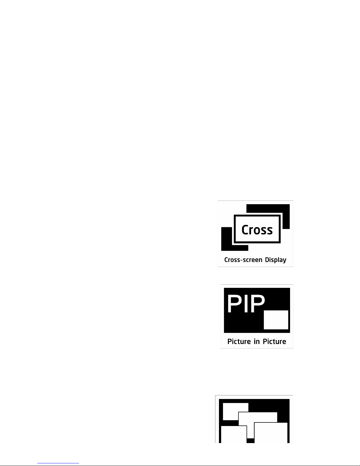
Cross-screen Displaying
Each signal can be displayed in the cross-screen state, which
means adjacent screens can jointly display the content of a
single signal to form the whole graphics as a “window”.
Customers can also zoom the windows drag them to
everywhere on the screen-wall.
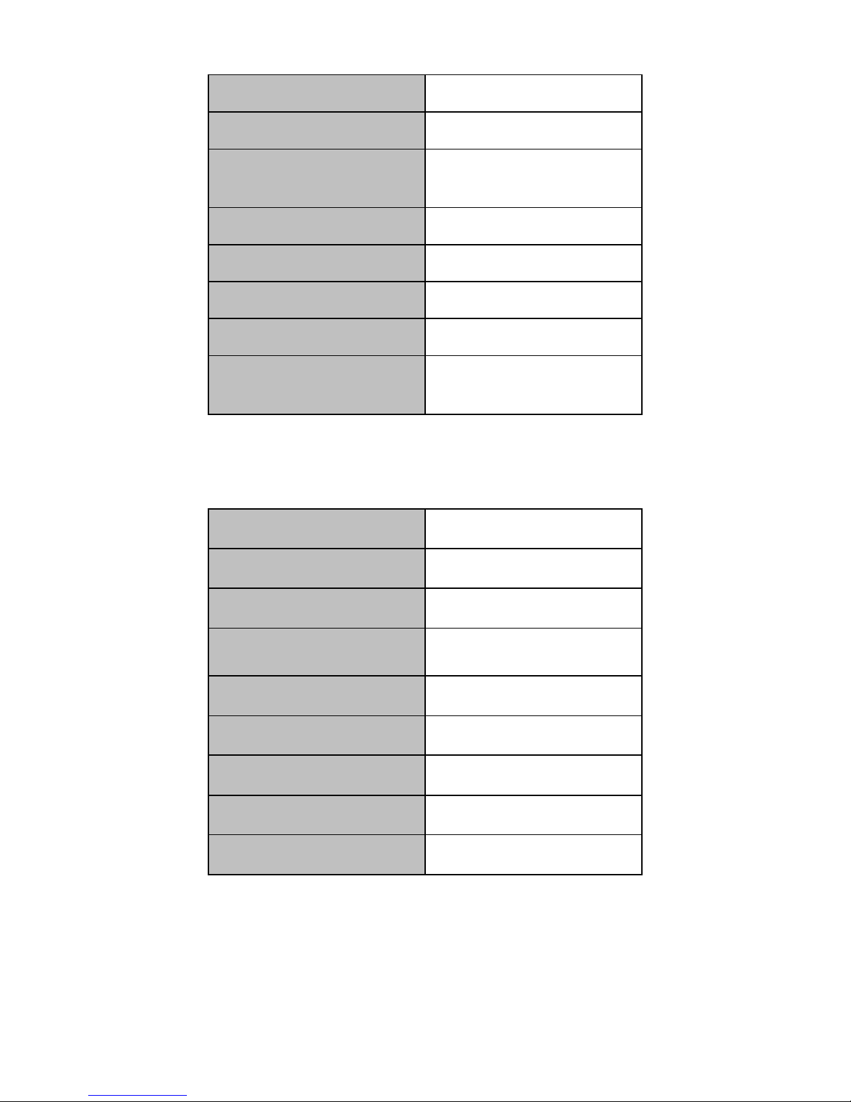
Picture in Picture
A window can be overlaid upon an other windows forming the
“picture in picture”. Moreover, the overlaid window is not
restricted inside the boundary of the underneath one which
offers flexibility to the layout of display.
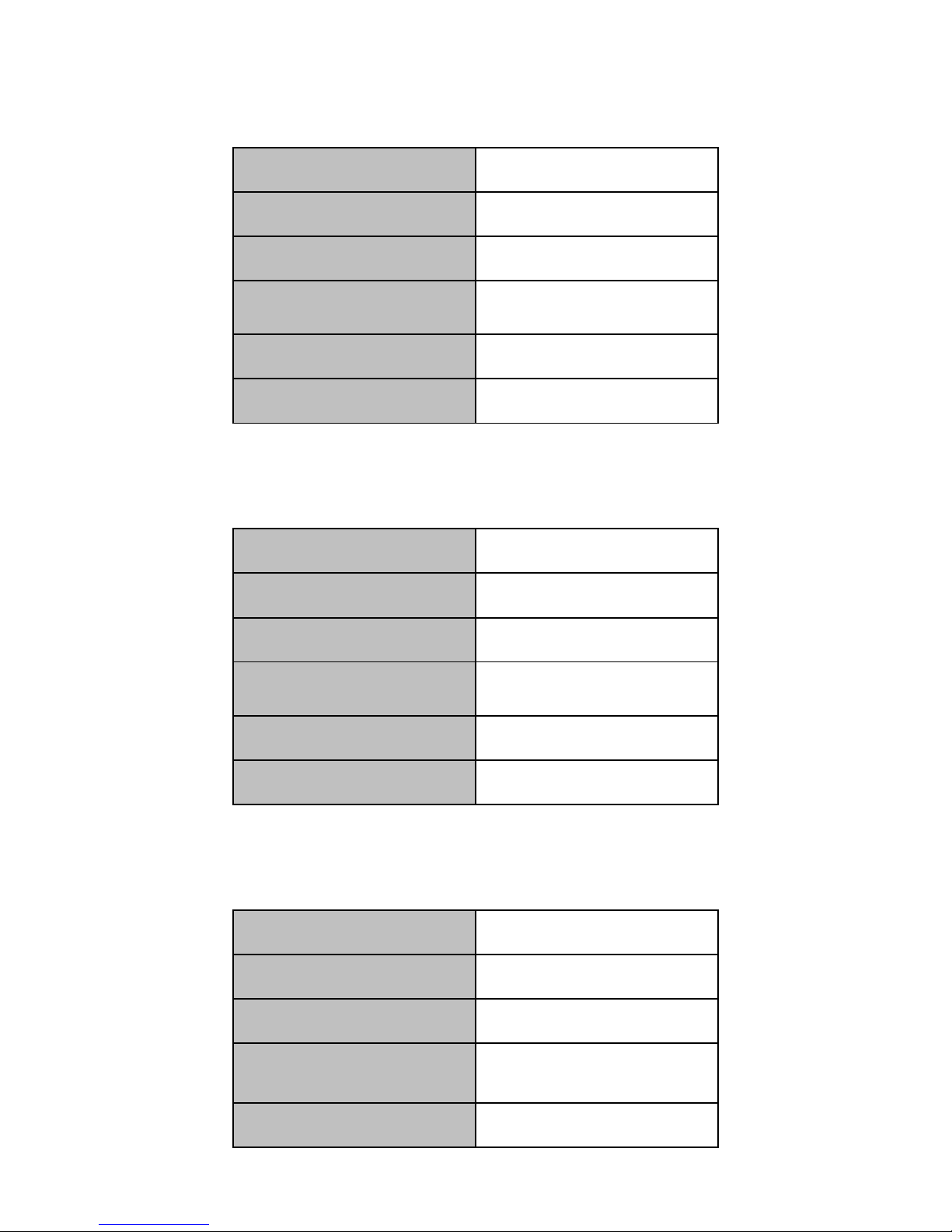
Four Windows per Screen

Video-Wall processor supports maximum four windows in a single screen allows users to
view more video signals with limited screens. The layout of the windows can be configured
separately which offers flexibility and convenience.
Input Signal Preview
All input signals can be previewed in the UI of software
before being displayed on the screens. It enables the
operator to detect the input status and display signals
correctly.
Other Functions
CrossPoint Switch
Video-Wall processor employs crosspoint switch technology which offers high speed
switching and transmission. Comparing to the “bus” switching architecture that all the
signals need to share the bandwidth of bus for transmission, crosspoint switch assigns each
signal a unique channel to avoid collision,delay, and instability, which contributes to real-
time displaying for all video signals.
FPGA architecture
Employing the pure hardware FPGA architecture with self-developed core algorithm
provide Video-Wall processor excellent image processing performance. Abandoning
embedded operation system preventing Video-Wall Processor from crashes, collisions, blue
screen, and viruses which commonly suffered by software architecture. It is highly stable to
ensure uninterrupted operation of 7x24, and meet the increasingly strict demand of market.
Card to Main-board Plugging structure
The main modules including input card,output card, switch card control card, cooling fan,
and power supply are all designed as plugging structure with the main-board which make it
very flexible and convenient for customer to configure the product based on every special
demand. It is unnecessary to disassemble the whole device when replacing the module with
fault. It also supports the ‘hot-plugging’ for input and output cards which means that
customer can plug and pull out the input or output card when the workstation is in process of
working. No restarting of refreshing is needed, and other signals will not be affected.
Resolution Real-Time Total Adaptation (RRTA)

Video-Wall processor employs RRTA( Resolution Real-time Total adaptation) technology
in order to support customised resolutions for different groups of screens, in other words the
resolution for each group of screens can be configured separately in the software which
offers flexibility and convenience for daily application and management .
Graphic Cropping and Signal Upscaling
The graphics of all input video signals can be freely cropped to remove the black edge.
Moreover, customer can zoom in and out any section of the video graphics after cropping.
The upscaling process ensures the zoomed section to be displayed without loss.
Ultra-high Resolution background Image
The built-in storage in Video-Wall Processor allows to store multiple ultra-high resolution
static ‘pixel-to-pixel’ background images which can be uploaded, displayed, and switched
through the software. With extra graphic workstation, the displaying of ultra-high resolution
dynamic background-image can also be achieved to meet specific and professional
requirements.
Character Superimposition
Video-Wall processor supports character superimposition to each input signal channel for
users to identify the signal source. Users can also customise the font, size, position, and
color of the superimposed character.
Scenes Saving, Loading, and Displaying in Loop
Any configuring arrangement of video signal displayed on screen wall can be saved as
“scenes”. Video-Wall processor supports up to 32 scenes to be saved and unlimited scenes
loaded. Customer can also set the scenes to be loaded and displayed in loop.
HDCP-Compliant
HDMI /DVI input card of Video-Wall processor supports HDCP , which enables HDCP
encrypted content to be displayed.
Redundant Power Supply
Video-Wall processor can be configured with dual power supply based on demand. For
circumstances if the power source is not stable, the redundant power supply is highly
suggested to connected to different power source or self-built UPS. In the condition of stable
power source, the device will works on load balancing for each power supply. Once a fault

occurs to the one of the power source, the redundant power supply will start running
automatically to ensure un-interruptible operation.
Controlling and Management
The Video-Wall processor controlling software allows users to manage and control the
processor on PC. It supports Windows2000/XP/Vista/7/8. The Video-Wall processor and
controlling PC can be connected by using CAT5/6 cable(TCP/IP) or RS232 cable. The
software can also control up to 4 extra traditional matrix switchers when they are
cascade(RS232) to the processor.. The Video-Wall processor can also be controlled by
employing the specific controlling keyboard(RS232).
System Diagram of Video-Wall Processor
3. Specifications
3.1 Input card
3.1.1 Input Port - VGA
Signal Format
RGBHV
Maximum Resolution
1920*1200
Signal Format
RGBHV
Color Depth
32bits/pixel
Horizontal Scanning Ration
15KHz-90KHz
Synchronization
Separate sync
Customised EDID
YES
Impedance
75Ω
Reference Level
0.7Vp-p
Physical Port
RGB: 15pins D-sub(DB15/DE-
15F)
3.1.2 Input Port - YPbPr
Signal Format
Component EIA-770.2-A
Maximum Resolution
1920*1080
Color Depth
32bits/pixel
Horizontal Scanning Ration
15KHz-90KHz
Synchronization
Separate sync
Customised EDID
YES
Impedance
75Ω
Reference Level
0.7Vp-p
Physical Port
RCA*3
3.1.3 Input Port - DVI

Signal Format
DVI-D digital T.M.D.S. signal
in DVI 1.0
Maximum Resolution
1920*1200
Color Depth
32bits/pixel
Signal Level
T.M.D.S 2.9V-3.3V
Customised EDID
YES
Impedance
50Ω
Maximum Data Rate
4.95Gbps
Physical Port
24+5 pins/DVI-I
3.1.4 Input Port - CVBS
Standard
PAL/NTSC
Resolution
480i/576i
Impedance
75Ω
Reference Level
1Vp-p
Physical Port
BNC
3.1.5 Input Port - SDI
Signal Format
HD/3G-SDI
Resolution
720p/1080p
Impedance
75Ω
Maximum Data Rate
3Gbps
Physical Port
BNC
3.1.6 Input Port - HDMI
Standard
HDMI 1.3
Maximum Resolution
1920*1200
HDCP
Yes
Customised EDID
YES
Maximum Data Rate
4.95Gbps
Physical Port
HDMI Type A
3.1.7 Input Port - Dual-link DVI
Signal Format
Dual-link DVI
Maximum Resolution
4K*4K
Impedance
50Ω
Customised EDID
YES
Maximum Data Rate
9.9Gbps
Physical Port
24+5 pins/DVI-I
3.1.8 Input Port - Optical Fibre
Signal Format
Single mode optical signal
Maximum Resolution
1920*1200
Front-end Device
TriF-T1SD or TriF-T1SG
Maximum Transmission
Distance
10km
Physical Port
LC

3.2 Output Card
3.2.1 Output Port - DVI/VGA
Signal Format
DVI-I in DVI 1.0 standard
Maximum Resolution
1920*1200
Color Depth
32bits/pixel
Maximum Transmission
Distance
25m(DVI)
Physical Port
24+5 pins/DVI-I
(Adapter required for VGA output)
Signal Level
T.M.D.S. 2.9V-3.3V
Impedance
50Ω
3.2.2 Output Port - Twisted Pair
Signal Format
Twisted pair differential signal
Maximum Resolution
1920*1200
Color Depth
32bit/pixel
Maximum Transmission
Distance
100m
Physical Port
LC
3.2.3 Output Port - SDI
Signal Format
HD-SDI/3G-SDI
Resolution
720p/1080p
Impedance
75Ω

Signal Format
HD-SDI/3G-SDI
Output Backup
Yes
Physical Port
BNC
3.2.4 Output Port - Optical Signal
Signal Format
Single mode optical signal
Maximum Resolution
1920*1200
Rear-end Device
TriF-R1SI
Maximum Transmission
Distance
10km
Physical Port
LC
3.3 Models and Scales
Models
Features
Video-Wall Processor 380
Two windows per screen
Video-Wall Processor 580
Four windows per screen
Models
Scales
Dimension (mm)
Input
Output
DVI/VGA/HDMI/SDI/YPbPr/
Optical/Twisted-pair/CVBS
Dual-link DVI
/DisplayPort
Video-Wall
Processor 380
2U
440/482(W)*380(D)*88.1(H)
8
4
8
4U
440/482(W)*380(D)*175(H)
16
8
16
8U
440/482(W)*380(D)*352.8(H)
32
16
36
14U
440/482(W)*380(D)*619.5(H)
64
32
72
20U
440/482(W)*380(D)*886.2(H)
128
N/A
72
28U
440/482(W)*380(D)*1241.8(H)
128
36*
144
Models
Scales
Dimension (mm)
Input
Output
DVI/VGA/HDMI/SDI/YPbPr/
Optical/Twisted-pair/CVBS Dual-link DVI
/DisplayPort
Video-Wall
Processor
580
4U
440/482(W)*380(D)*175(H)
24
4*
8
8U
440/482(W)*380(D)*352.8(H)
52
8*
18
14U
440/482(W)*380(D)*619.5(H)
96
16*
36
22U
440/482(W)*380(D)*975.1(H)
128
36*
72
4U
440/482(W)*380(D)*175(H)
16
8
8
8U
440/482(W)*380(D)*352.8(H)
32
16
18
14U
440/482(W)*380(D)*619.5(H)
64
32
36
20U
440/482(W)*380(D)*886.2(H)
128
N/A
36
28U
440/482(W)*380(D)*1241.8(H)
128
36*
72
*means dual-link dvi input cards are only effective in specified input slots
4. User Guide
4.1 Operation and Configuration
(1)Operation and connection
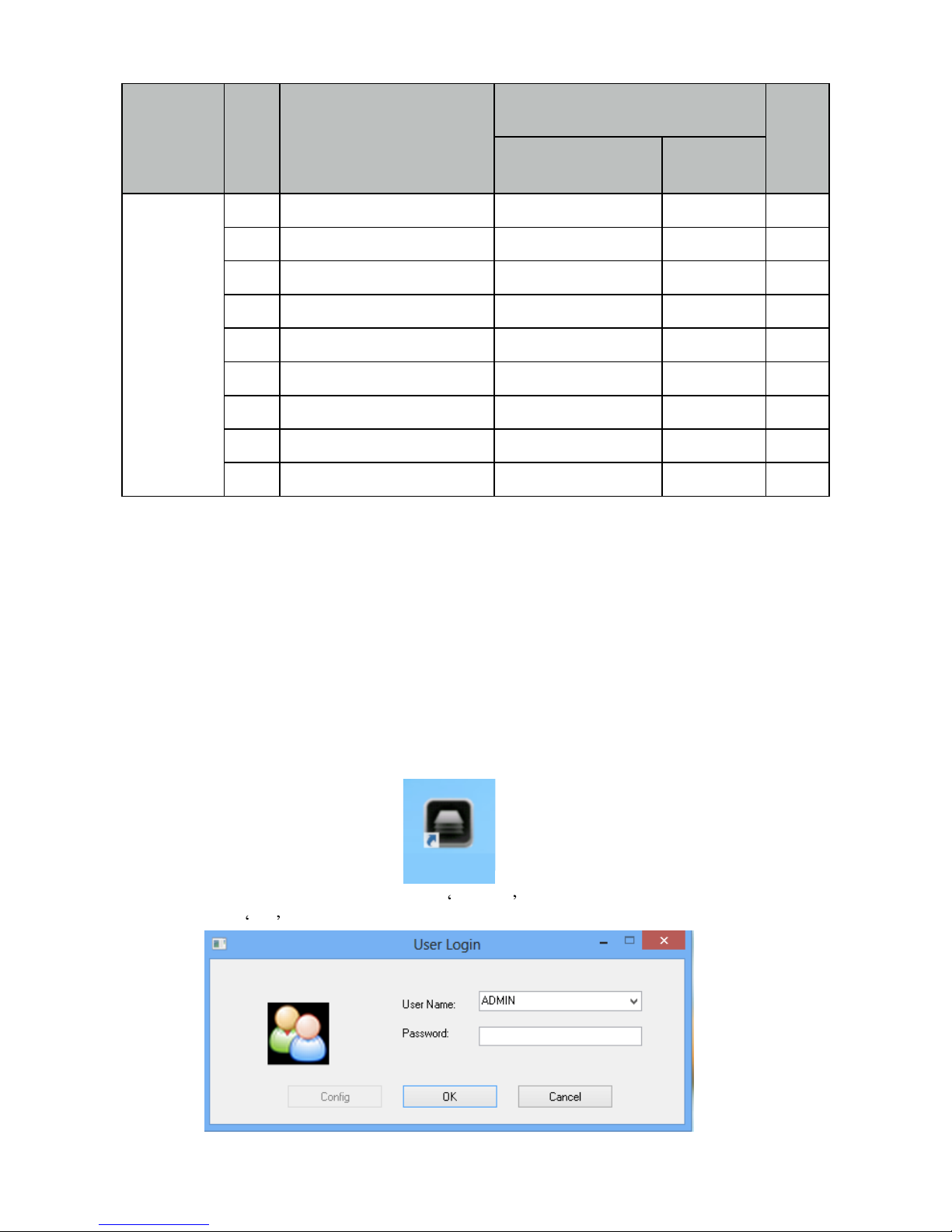
Double clicking the icon on desktop after the software has been installed.
The log in windows will pop up, using the ADMIN as user name and left the password
blank, then click OK .
HMV260

The controlling software menu consists of three modules which are the ‘Software
Operation’, ‘Basic Operation’, and ‘Tools’.
Firstly, clicking ‘Communication Setting’ on the ‘Software Operation’ .
The connection configuration window will pop up. If the ‘NET Connection’ has been chose,
the default IP address and port number of the processor are ‘192.168.1.65’ and ‘1024’. If the ‘COM
Connection’ has been chose, select the correct COM port, and make sure the baud rate is 9600.
Then clicking OK to save the settings.
After that, clicking ‘Connect’ to connect the processor.
(2)User Administration
Clicking ‘Users’ on the ‘Tools” menu
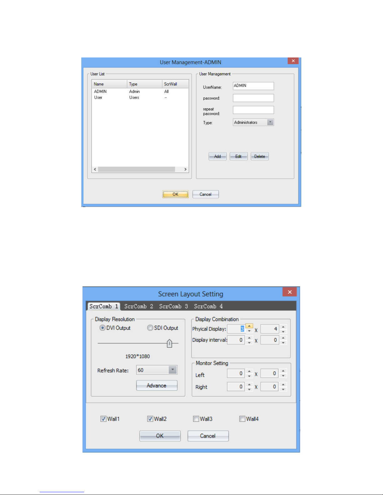
On the pop-up window, the username, password for users to log-in can be configurated. You can
also set the level of access by select one item on the ‘Type’ drop list.
(3) Video-wall settings
Clicking ‘Layout’ on the ‘Software Operation’ to set the video-wall. users can set the output
resolution, layout, and the gap between displays for up to 4 groups of video-wall.
For example, the figure below shows the setting of video-wall 1 which the output resolution is
1920*1080, layout is 2*3, and gap is 0.

(4) Channel Mapping
Clicking the ‘group’on the ‘Basic Operation’menu to set the output mapping from
logical channel to physical port.
(5) Signal Source Setting
The signal source list located on the left of the software UI. The icon of each signal source will
turns green if input signal has been detected on corresponding channel.
Users can configurate the settings of the signal source by right-clicking one of them.

OSD:
OSD is for character superimposition, user can enter the text which need to be displayed overlaying
the video on the textfield. The position of the text overlaying on the video can also be defined by
setting values for ‘Horizontal Pos’ and ‘Vertical Pos’. There are three modes of OSD can be chose:
Disable OSD Mode: No character superimposition
OSD Mode 1: Character superimposition with transparent background
OSD Mode 2: Character superimposition with pure colour background
Modify name:
The name of the signal source can be specified by ‘Modify name’, it will helps to identify and
mange the signal sources.
Add mode:
Users can cropping the input video signal by ‘Add Mode’. The parameters are:
H Start: The horizontal starting pixel of the cropped signal
V Start: The vertical starting pixel of the cropped signal
Width: The width of the cropped video signal
Height: The Height of the cropped video signal

VGA Signal Property
User can set the parameters for VGA signal by ‘VGA Signal Property’.
VGA <---> YPbPr
Selecting the ‘VGA <---> YPbPr’ to choose the signal format of the VGA input channel.
Update EDID
Users can configurate the EDID of the input port for abnormal resolution. Clicking ‘EDID’ on the
‘Tools’ menu

Click ‘File ---> Open EDID’ to open one current EDID configuration file(.dat), then modify it to
create an new file.
Click , choose modify mode, choose the first block on ‘Detailed Timings’ menu,

H Active: the horizontal pixels
V Active: the vertical pixels
Pixel: the refresh rate ( Recommended not to modify)
When finish configuration, don’t replace the previous file, save as an new file and save it one the
PC. Then right clicking the signal source and click ‘Update EDID’, choose the created file.
(6) Window Controlling
Select one signal source by clicking the icon, then customise a rectangular zone by mouse dragged
with its left button to select a region on the the grey area in UI corresponding to the video-wall,
after that a windows will be created for displaying on the video-wall. Windows can also be created
by click ‘New Open’ on the’Basic Operation’ menu. Users can customise the size and the position
of the windows anywhere within the video-wall
.

The processor supports the maximum of 4 windows on a single display. The layer of the windows
can be set by right clicking the window and select ‘Top’ and ‘Bottom’.
(7) Test Signal
Users can test the connection between processor and displays by transmitting the signals of pure
colour or grid to the displays.
(8) Scene
Saving and Loading
Clicking the ‘Save’ on the ‘Basic Operation’ to save the displaying status of the video-wall
including the layout, size, and signal source of windows.

Users can load the ‘scenes’ by select one scene on the ‘Scene List’which located on the left side of
the software UI.
All the saved scenes can be loaded and displayed on loop by clicking ‘Loop’ on ‘Basic Operation’
(9)Advanced settings
This manual suits for next models
1
Table of contents


