eBridge 4PCRX User manual

IP over Coax Receiver
Installation Guide
Models Include:
eBridge4PCRX
- Four (4) Channel Receiver
Rev. 072412 More than just power.™
I.T.E. 43KC
Z1409

- 2 - eBridge4PCRX
Overview:
The eBridge4PCRX is a CAT5 to Coax cable Managed Ethernet Midspan receiver. The receiver enables fast 10/100Base-T
Ethernet digital communication to be received over Coax cable. An eBridge4PCRX receiver sends power over the coax to
the eBridge1PCT 15.4W (PoE) or eBridge1PCTX 30W (PoE+) transmitter under PoE protocol. The eBridge1PCT/PCTX in
turn delivers that power to a PoE enabled camera or IP device. The eBridge4PCRX will not deliver power to non compliant
devices, thus avoiding accidental power turn into improperly connected analog cameras. These plug and play units facilitate
system upgrades from analog to IP cameras/devices utilizing existing legacy Coax and eliminating the costs and labor asso-
ciated with installing new network cabling. In addition, data transmission and power over the Coax is possible up to 500m
in comparison to 100m Ethernet maximum distance (see Maximum Length of Coax Type vs. Camera Power/PoE Class, pg.
3). A maximum range from head end to the PoE camera/device is 610m taking into consideration that 100m of structured
cable may be deployed at each end. Altronix offers model VertiLine563 Rack Mount Power Supply/Charger which provides
56VDC output which will power up to two (2) eBridge4PCRX receivers with up to eight (8) PoE+ cameras/devices.
Features:
Installation Instructions:
Wiring methods shall be in accordance with the National Electrical Code/NFPA 70/ANSI, and with all local codes and
authorities having jurisdiction. Wiring should be UL Listed and/or Recognized wire suitable for the application.
eBridge4PCRX is not intended to be connected to outside plant leads and should be installed indoors within the protected
premises. The eBridge4PCRX is intended for indoor use only. This product is intended to be supplied by a UL Listed Power
Supply rated from 48VDC to 56VDC.
Elevated Operating Ambient - If installed in a closed or multi-unit rack assembly, the operating ambient temperature of the
rack environment may be greater than room ambient. Therefore, consideration should be given to installing the equipment
in an environment compatible with the maximum ambient temperature (Tma) specified by the manufacturer.
Reduced Air Flow - Installation of the equipment in a rack should be such that the amount of air flow required for safe op-
eration of the equipment is not compromised
Mechanical Loading - Mounting of the equipment in the rack should be such that a hazardous condition is not achieved due
to uneven mechanical loading.
Agency Listings:
• UL/CUL Listed for Information
Technology Equipment (UL 60950-1).
• CE approved.
• C-Tick compliant.
Input:
• 48VDC to 56VDC UL Listed power supply
(attention to observe polarity).
Note: Use 54V to 56V power supply to achieve full
power per IEEE802.3 at standard.
Power Consumption:
• 48VDC/2.6A, 56VDC/2.6A,
eBridge1PCTX (30W): Powered by eBridge4PCRX.
eBridge1PCT (15W): Powered by eBridge4PCRX.
Ethernet:
• Connectivity: RJ45, auto-crossover.
• Wire type: 4-pair Cat-5 or better structured cable.
• Distance: up to 100m.
• Speed: 10/100BaseT, half/full duplex, auto negotiation.
• Throughput is rated to pass 25mbps of data at
distances up to 500m. With proper headend
equipment multiple Megapixel cameras can be used.
Coax:
• Distance: up to500m.
• Connectivity: BNC, RG-59/U or similar.
LED Indicators:
• Blue LED - Coax link connection.
• Green LED - Power.
LED Indicators (cont’d):
• Yellow and Green LED (RJ45) IP Link status,
10/100Base-T/active.
Environmental:
• Operating temperature: -10ºC to 50ºC (14ºF to 122ºF).
• Storage temperature: -30º to 70ºC (-22º to 158ºF).
• Humidity: 20 to 85%, non-condensing.
Applications:
• Retrofit digital IP cameras in an analog CCTV
installation.
• Works with Megapixel, HD720, HD1080 and VGA
(SD) cameras (see note, pg. 2).
• Extend Network link distance in an industrial
environment.
• Upgrade deployed CCTV Coax to a digital network
in Retail, Hospitality, Arenas, Casinos, Airports,
Schools, Hospitals, Transportation, etc.
Accessories:
• eBridge1PCT: Single port ethernet/PoE transceiver.
• eBridge1PCTX: Single port ethernet/PoE or PoE+
transceiver.
• VertiLine563: 56VDC Rack Mount Power Supply/
Charger.
• RE2: Rack mount battery enclosure. Accommodates up
to four 12VDC/7AH batteries (batteries not included).
Mechanical:
• Dimensions (H x W x D approx.):
1.7” x 5.25” x 9.25” (43.8mm x 133.35mm x 235mm)
eBridge4PCRX - 3 -
Circuit Overloading - Consideration should be given to the connection of the equipment to supply circuit and the effect that
overloading of the circuits might have on overcurrent protection and supply wiring. Appropriate consideration of equipment
nameplate rating should be used when addressing this concern.
Reliable Earthing - Reliable earthing of rack-mounted equipment should be maintained. Particular attention should be given
to supply connections other than direct connections to the branch circuit (e.g. use of power strips).
1. Affix rubber pads to eBridge4PCRX for shelf installation (Fig. 5, pg. 8).
2. Unit should be located in proximity to ethernet switch/network, NVR or video server.
3. Connect UL Listed 48VDC/56VDC (attention to observe polarity) UL Listed power supply to jack marked [Input 1]
using two pin plug in connector (supplied) (Fig. 1, pg. 2). Use 22AWG-16AWG wire for this connection.
4. Connect structured cable from ethernet switch/NVR (network video server) to RJ45 jack marked [10/100BaseT]
(Fig. 1, pg. 2).
5. Connect Coax cable to BNC connector marked [Data In] (Fig. 1, pg. 2).
Note: The eBridge is designed to accommodate Megapixel, HD720, HD1080 and VGA (SD) cameras. It is important to
note that some high resolution and high frame rate cameras may demand faster headend processing ability, such as a PC
graphics card to present a quality image. If the headend processing equipment is insufficient in speed, the image may show
pixelation and latency. It is advisable to pre-test system if unsure. Alternatively, frame rate and resolution may be reduced
to accommodate system equipment.
Technical Specifications:
Parameter Description
Connections BNC for Coax link. RJ45 for ethernet link.
Input power requirements 48VDC/2.6A, 56VDC/2.6A.
Indicators
Blue: Coax Link.
Yellow (RJ45 connector): On - Link, Off - No Link, Blinking - Activity.
Green (RJ45 connector): On - 100Base-TX, Off - 10Base-T.
Green: Power.
Environmental Conditions
Operating Ambient Temperature: UL60950-1 -10ºC to 50ºC (14ºF to 122ºF).
Relative humidity: 85%, +/ --- 5%.
Storage Temperature: -30º to 70ºC (-22º to 158ºF).
Operating Altitude: --- 1000 to 6,561.679 ft. (--- 304.8 to 2000m).
Regulatory Compliance UL/CUL Listed for Information Technology Equipment (UL 60950-1). CE approved.
Weights (approx.) Product: 1.35 lbs. (0.61 kg); Shipping: 1.7 lbs. (0.77 kg)
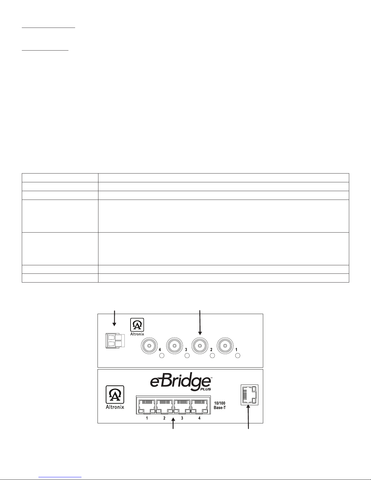
Fig. 1
Structured Cable from
Ethernet Switch/NVR
LAN or laptop connection
enables programming and
status monitoring.
Back of
Unit
Front
of Unit
Input 1
Coax Cable from
eBridge1PCT or eBridge1PCTX
48VDC/2.6A,
56VDC/2.6A
Ethernet
--
+
- 4 - eBridge4PCRX
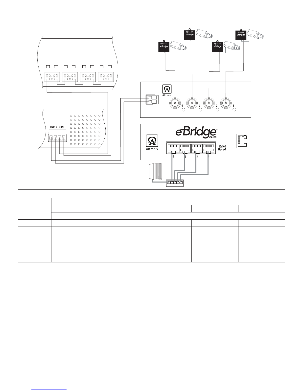
Single IP Camera:
Fig. 2
Maximum Length of Coax Type vs. Camera Power/PoE Class:
Camera
Power/
PoE Class
Coax Type
RG59/U - 23AWG RG59/U - 22AWG RG59/U - 20AWG RG59/U - 18AWG RG6/U - 18AWG
Max. Length (meters)
13W/0 260.6 335.3 500 500 500
4W/1 500 500 500 500 500
6.5W/2 500 500 500 500 500
13W/3 260.6 335.3 500 500 500
19W 152.4 198.1 315.5 500 500
25W 118.9 150.6 239.3 500 365.8
eBridge4PCRX User Interface and Programming:
Note: A constant PC connection is not required for proper operations and is used as a local programming/monitoring tool only.
Step 1. Set Local Area Connection of your laptop to DHCP mode.
For Windows XP:
a. Open Network Connections by clicking Start button, then clicking Settings, then clicking Network Connections.
b. Right click the Local Area Connection. Click Properties. Administrator permission required
If you are prompted for an administrator password or confirmation, type the password or provide confirmation.
c. Double click Internet Protocol (TCP/IP) menu item.
d. Choose the Obtain an IP address automatically option.
e. Click OK. Close all windows.
For Windows Vista:
a. Open Network Connections by clicking the Start button Picture of the Start button, clicking Control Panel,
clicking Network and Internet, clicking Network and Sharing Center, and then clicking Manage Network
connections.
b. Right click the Local Area Connection icon, and then click Properties. Administrator permission required
If you are prompted for an administrator password or confirmation, type the password or provide confirmation.
Input 1
Ethernet
--
+
IP Camera
eBridge1PCTX
IP Camera
eBridge1PCTX
IP Camera
eBridge1PCTX
IP Camera
eBridge1PCTX
500m 500m
500m500m
Up to
100m
Ethernet Switch
Up to
100m
Up to
100m Up to
100m
NVR Network
Video Server
(Head End
Equipment)
VertiLine563 (cross section of rear)
eBridge4PCRX (rear)
eBridge4PCRX (front)
BAT4
+ + --- ---
BAT3
+ + --- ---
BAT2
+ + --- ---
BAT1
+ + --- ---
RE2 - Rack Battery Enclosure (cross section of rear)
with four (4) 12VDC/7AH batteries
(Altronix model # BT126)

eBridge4PCRX - 5 -
c. Click the Networking tab. Under this connection uses the following items, click either Internet Protocol
Version 4 (TCP/IPv4) or Internet Protocol Version 6 (TCP/IPv6), and then click Properties.
d. To specify IPv4 IP address settings, click Obtain an IP address automatically, and then click OK.
e. To specify IPv6 IP address settings, click Obtain an IPv6 address automatically, and then click OK.
For Windows 7:
a. Open Network Connections by clicking the Start button Picture of the Start button, clicking Control Panel,
clicking Network and Internet, clicking Network and Sharing Center, and then clicking Change Adapter
Settings.
b. Right click the Local Area Connection icon, and then click Properties. Administrator permission required
If you are prompted for an administrator password or confirmation, type the password or provide confirmation.
c. Click the Networking tab. Under this connection uses the following items, click either Internet Protocol
Version 4 (TCP/IPv4) or Internet Protocol Version 6 (TCP/IPv6), and then click Properties.
d. To specify IPv4 IP address settings, click Obtain an IP address automatically, and then click OK.
e. To specify IPv6 IP address settings, click Obtain an IPv6 address automatically, and then click OK.
Step 2. Connect a laptop or PC to the Ethernet port of your eBridge4PCRX unit, or connect your eBridge4PCRX and
laptop/PC to a DHCP router if eBridge4PCRX is in DHCP mode. The eBridge4PCRX unit should be powered up
at this moment.
Step 3. Open a browser window (it is necessary to update your browser software to the latest version so that the pages
display and function correctly).
Step 4. Enter the eBridge4PCRX IP address (the default IP address is 192.168.168.168), or enter the eBridge4PCRX
host name if in DHCP mode (default host name is “eBridge4PCRX1”,) into the address bar.
Status page will be displayed.
Configuring eBridge4PCRX for Network Connection:
Since every Network Configuration is different, please check with your Network Administrator to see whether your
eBridge4PCRX should use static IP addresses, or DHCP assigned IP addresses and/an Inbound Port assignment prior to
setting up network connection.
1. Click Network Settings link.
If you are prompted for an administrative password, type and submit the password.
Note: Default settings have password requirements turned off .
2. Network Setup page will be displayed. You may now configure your eBridge4PCRX for network connection.
Figure X-X is a screenshot of the NETWORK SETTING MENU. This menu is for configuring the eBridge4PCRX units
for a network connection.
Figure X-X Network Menu – LAN
Network Type:
Static IP User can set a fixed IP for network connection.
DHCP DHCP server in LAN will automatically an assign IP configuration for the network connection.
IP This field shows the eBridge4PCRX current IP Address. A static IP address must be set manually.
If DHCP this value will be assigned automatically.
Subnet Mask This field shows the subnet mask for your network so the eBridge4PCRX will be recognized within the
network. If DHCP is selected, this value will be assigned automatically.
Inbound Port Port number for HTTP/WEB communication.
Host Name Name of the eBridge4PCRX device on the LAN
Additional Information:
1. If using DHCP, all settings will be detected automatically.
While DHCP is a useful tool for determining the network settings, if you set up your eBridge4PCRX in this manner
its IP address may change at different times for different reasons, particularly after a power failure. If the IP address
of the eBridge4PCRX changes, you may have difficulties accessing your eBridge4PCRX locally and/or remotely.
It is strongly recommended that you connect via host name when units configured as DHCP.
Please do not set the DHCP address issued to the eBridge4PCRX by the router as its static IP address unless you
take specific steps that program your router to prevent such address conflicts.

- 6 - eBridge4PCRX
2. If using a Static IP (recommended), you will need to input the information manually. In order for DDNS to work,
you must enter valid data, compatible with your network, for all of the network setting fields: IP address,
Subnet Mask, Inbound Port and Host Name.
3. If you are connecting through a router, make sure that you have ‘opened up’ all the required network ports in the port
forwarding section of your router’s setup options. That is, you have directed the router to send any incoming traffic
using those IP ports to the LAN IP address of the eBridge4PCRX. Useful information about router port
forwarding can be found at www.portforward.com. Different routers may use different terms for port forwarding
function. For instance, D-Link calls it virtual server, Netopia calls it pinholes.
The default port for eBridge4PCRX is: 80
Note: Port 80 is the default port used for web browsing. Because of this, in order to prevent the average user from
hosting a web server, most ISPs BLOCK traffic using port 80 from reaching the average site. If you only plan to
monitor your eBridge4PCRX on a LAN, you can use port 80, and don’t have to concern yourself with routers.
However, if you desire remote access to your eBridge4PCRX, you MUST select functional ports and set up the
port forwarding in your router. Other ports, such as 8080 and 8000 are sometimes blocked by ISPs as well.
What port(s) should be used? There are 65,535 valid IP ports to choose from.
These are broken down into three groups:
• Well-Known Ports 0 through 1023.
• Registered Ports 1024 through 49151.
• Dynamic and/or Private Ports 49152 through 65535.
So, rather than encounter a port conflict by choosing a port commonly used for another purpose (like port 25 for SMTP
mail or port 448 for secure sockets), choose an ‘unusual’ port number. For example, add 50,000 to your house number:
50,123 is less likely to lead to a port conflict. For a list of the known and registered ports,
see http://www.iana.org/assignments/port-numbers.
Reset Features:
Reset Password:
1. Disonnect two pin plug connector from the jack marked [Input 1] (Fig. 3, pg. 6).
2. Reconnect two pin plug connector to the jack marked [Input 1] while depressing
the [RESET button] on the side of the eBridge4PCRX (Fig. 3, pg. 6).
Reset IP to Factory Settings:
1. During normal operation depress the [RESET button] on the side of the eBridge4PCRX for approximately
1 second (Fig. 3, pg. 6).
2. Factory settings are: DHCP server and the IP address is [192.168.168.168].
Reset
Ethernet
Fig. 3
eBridge4PCRX - 7 -
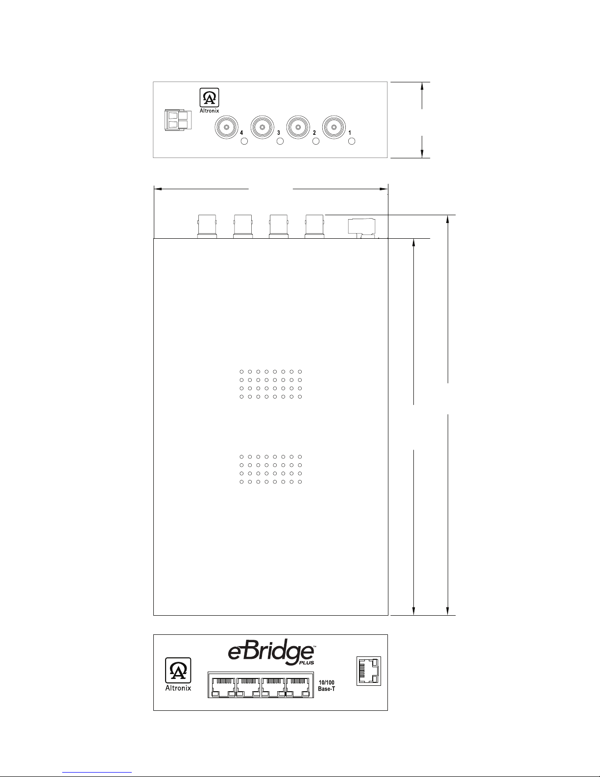
eBridge4PCRX Chassis Mechanical Drawing & Dimensions (H x W x D approx.):
1.7” x 5.25” x 9.25” (43.8mm x 133.35mm x 235mm)
Fig. 4
8.42”
213.9mm
5.25”
133.35mm
1.7”
43.8mm
9.25”
235mm
Ethernet
Input 1
--
+

- 8 - eBridge4PCRX
Mounting Options:
Shelf Installation
1- Position and affix rubber pads (C) (included) at each
corner on the bottom of the unit (Fig. 5).
2- Place unit in desired location.
Fig. 5
Altronix is not responsible for any typographical errors.
140 58th Street, Brooklyn, New York 11220 USA, 718-567-8181, fax: 718-567-9056
IIeBridge4PCRX G08P MEMBER
Mounting Hardware (Included):
Four (4) rubber pads.
C
B
A
C
Left Side
Rubber Pad
Table of contents


