Tricor TCE-8000 Operating instructions

Coriolis TCM Series
Rev. 2.2


©2011 AW-Lake Company. All rights reserved. All trademarks are the property of their respective holders and are hereby acknowledged. TCE-8000PG-012011 Page | 3
TCE-8000 Transmitter Programming Guide
This guide contains instructions on how to reconfigure the TCE-8000 Coriolis transmitter using its integral
keyboard and display. There are two packaging configurations of the TCE-8000 transmitter: field mount
(cast aluminum housing) and panel mount (plastic housing). These programming instructions apply to
both. The TRICOR TCE-8000 transmitter’s keyboard and display consists of:
an LCD graphic display
two LEDs labeled “OK” and “ERR”
four pushbutton keys labeled “P,” “Reset,” “Display,”and “Info”
Normal Operation
When the TRICOR flow meter is operating properly, “OK” flashes green. With the factory defaults, the
display indicates FLOW RATE on the upper line and BATCH TOTAL on the lower line. When viewing this
display, press the “Reset” key to reset the BATCH TOTAL to zero. Press the “Display” key to view the
DENSITY on the upper line and TEMPERATURE on the lower line of the display. Press the “Display” key
to toggle back to the FLOW RATE and BATCH TOTAL display. You can reconfigure the normal operation
displays to show data other than the factory defaults (see DISPLAY programming).
Abnormal Operation
When the LED labeled “ERR” flashes red, the internal diagnostics of the transmitter is sensing that there
may be a measurement error occurring. Press the “Info” key to view the problem and to see additional
parameters that are important to the operation of the unit. Note: Press the “Info” key during normal
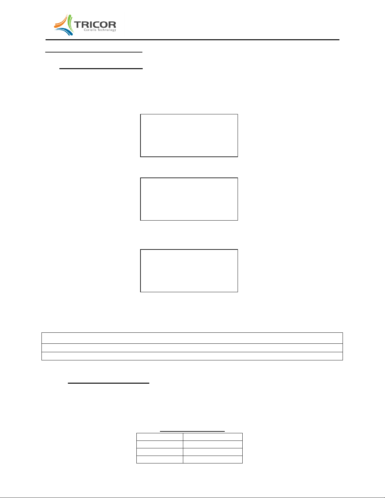
operation to view these additional parameters. The display that appears is similar to the following:
These parameters are important when discussing operational problems with a TRICOR service technician
and they correspond to the following data:
SA is the amplitude of Sensor A in millivolts
SB is the amplitude of Sensor B in millivolts
DR is the sensor DRive current in milliamps
PT is the resistance indicated by the Platinum Temperature probe in Ohms
FRE is the vibrating tube FREquency in Hz
TOT is the internal TOTalizer value
ZP is the captured Zero Point calibration in microseconds
RS485 is the address of the RS485 communication port
SA: 140 FRE: 142.74
SB: 140 TOT: 1007.69
DR: 5.51 ZP: -0.02
PT: 1071.2 RS485: 01

©2011 AW-Lake Company. All rights reserved. All trademarks are the property of their respective holders and are hereby acknowledged. TCE-8000PG-012011 Page | 4
TCE-8000 Transmitter Programming Guide
ZERO OFFSET procedure
Note: ON NEW INSTALLATIONS, A ZERO POINT CALIBRATION MUST BE PERFORMED TO
ENSURE ACCURATE METERING.
Shut off the flow and block in the flow line with a downstream valve to ensure that the flow rate is
truly zero.
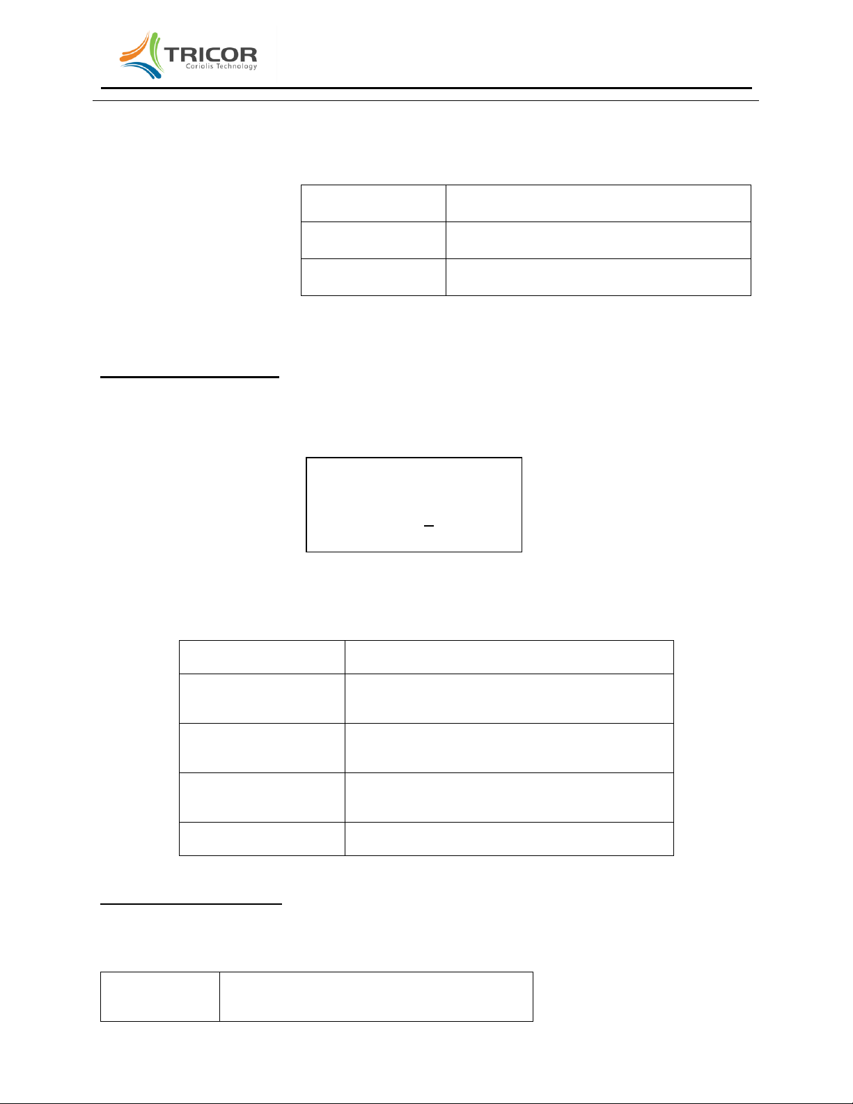
Press and hold the “P” key until the following screen appears:
Press the “P” key again and the following screen appears
Press the “UP” softkey to change 2206 to 2207, then press the “P” key. The following screens
appear:
Press the “SLOW” softkey for long averaging (about 30 seconds) or the “FAST” key for short
averaging (about 10 seconds) to initiate zero point calibration. Caution: Do not flow through the
sensor while the following screens are displayed:
The zero point calibration is complete. Press the INFO key to return to the ZERO OFFSET
display.
Press EXIT softkey to return to the RATE and BATCH TOTAL display.
*ENTER USER_CODE*
2206
LEFT UP EXIT
* USERCODE *
OKAY
MAIN MENU
ZERO OFFSET
UP DOWN EXIT
START OFFSET
PROCEDURE
SLOW FAST EXIT
MAKE ZERO
OLD ZERO: x.xxx uS
NEW ZERO: uS
*END OF ZERO POINT*
PRESS INFO TO RETURN
OLD ZERO: x.xxx uS
NEW ZERO: y.yyy uS
©2011 AW-Lake Company. All rights reserved. All trademarks are the property of their respective holders and are hereby acknowledged. TCE-8000PG-012011 Page | 5
TCE-8000 Transmitter Programming Guide
REPROGRAMMING OPERATION
FLOW DISP reprogramming
To enter the function that allows you to reconfigure the transmitter display of flow, total, density and
temperature, perform the following steps:
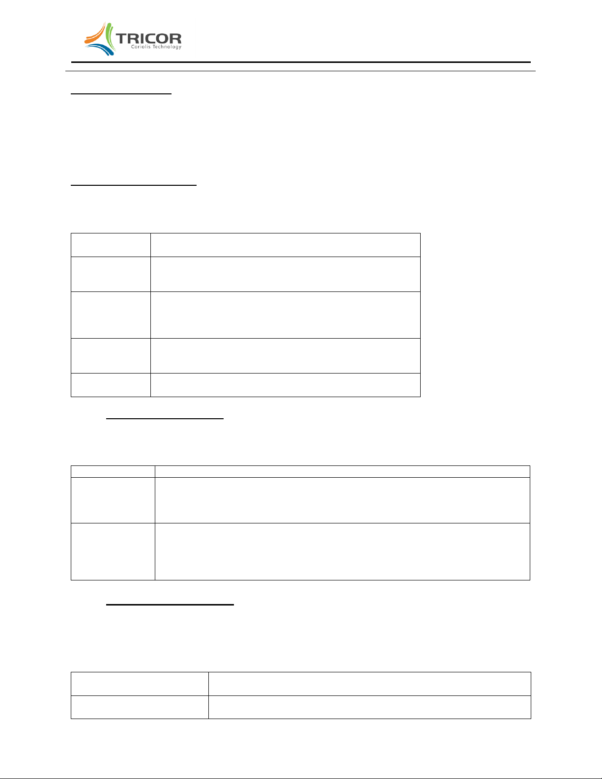
Press and hold the “P” key until the following screen appears:
Press the “DOWN” key and the following screen will appear:
Press the “P” key and the following screen will appear:
Press the “P” key to access the flow rate parameter(s) that can be changed under the FLOW
DISP submenu.
Displayed Parameter Description
FLOW UNITS select unit of measure for flow rate display
FLOW DP select decimal point location in flow rate display
DISP FILTER define filter value used to smooth flow rate display
FLOW UNITS programming
With FLOW UNITS displayed, press the “P” key to bring up the current flow rate units. Press the “UP” or
“DOWN” softkey to select the desired unit of measure. If the METER MODE selected in SETUP is MASS
METER the list consists of the following:
Mass Flow Rate Units
FLOW-UNITS
Description
G/S
Grams/second
KG/S
Kilograms/second
LB/S
Pounds/second
SELECT PROG-POINT
FLOW DISP
UP DOWN EXIT
MAIN MENU
ZERO OFFSET
UP DOWN EXIT
MAIN MENU
DISPLAY
UP DOWN EXIT

©2011 AW-Lake Company. All rights reserved. All trademarks are the property of their respective holders and are hereby acknowledged. TCE-8000PG-012011 Page | 6
TCE-8000 Transmitter Programming Guide
OZ/S
Ounces/second
T/S
Metric tons/second
ST/S
Stones/second
G/M
Grams/minute
KG/M
Kilograms/minute
LB/M
Pounds/minute
OZ/M
Ounces/minute
T/M
Metric tons/minute
ST/M
Stones/minute
G/H
Grams/hour
KG/H
Kilograms/hour
LB/H
Pounds/hour
OZ/H
Ounces/hour
T/H
Metric tons/hour
ST/H
Stones/hour
G/D
Grams/day
KG/D
Kilograms/day
LB/D
Pounds/day
OZ/D
Ounces/day
T/D
Metric tons/day
ST/D
Stones/day
If the METER MODE selected in SETUP is VOLUME METER the list consists of the following:
Volumetric Flow Rate Units
Flow Rate Unit
Description
CC/S
Cubic centimeters/second
L/S
Liters/second
UGAL/S
US gallons/second
LOZ/S
Fluid ounces/second
EGAL/S
English gallons/second
BBL/S
English barrels/second
CC/M
Cubic centimeters/minute
L/M
Liters/minute
UGAL/M
US gallons/minute
LOZ/M
Fluid ounces/minute
EGAL/M
English gallons/minute
BBL/M
English barrels/minute
CC/H
Cubic centimeters/hour
L/H
Liters/hour
UGAL/H
US gallons/hour
LOZ/H
Fluid ounces/hour
EGAL/H
English gallons/hour
BBL/H
English barrels/hour
CC/D
Cubic centimeters/day
L/D
Liters/day
UGAL/D
US gallons/day
LOZ/D
Fluid ounces/day
EGAL/D
English gallons/day
BBL/D
English barrels/day
With the desired flow rate unit displayed, press the “P” key; the display returns to FLOW UNITS. Note:
To compute volume flow, the device divides the measured mass by the measured density.

©2011 AW-Lake Company. All rights reserved. All trademarks are the property of their respective holders and are hereby acknowledged. TCE-8000PG-012011 Page | 7
TCE-8000 Transmitter Programming Guide
FLOW DP programming
When FLOW DP displays, press the “P” key to bring up the current position of the flow rate decimal point
position. Press the “LEFT” softkey to select the desired position of the flow rate decimal point, then press
the “P” key; the display returns to FLOW DP.
DISP FILTER programming
With DISP FILTER displayed, press the “P” key to bring up the current time constant (in seconds) for the
flow rate display. Press the “RIGHT” and “UP” softkeys to define the time constant between the limits of 0
and 99.9 seconds. Press the “P” key; the display returns to DISP FILTER. Note: The larger the time
constant used in the DISP FILTER, the steadier the rate display; however, it will take longer to reach final
value when a change in the flow rate is made. The factory default is 1.0 second for moderate filtering.
TOTAL DISP reprogramming
TOTAL DISP is below FLOW DISP is the DISPLAY submenu. Follow the steps above to get to FLOW
DISP then press the “DOWN” key to bring up TOTAL DISP.
Press the “P” key to access the totalizer parameters that can be changed under the TOTAL DISP
submenu.
Displayed Parameter Description
TOTAL UNITS select unit of measure for BATCH TOTAL display
TOTAL DP select decimal point location in BATCH TOTAL display
TOTAL UNITS programming
With TOTAL UNITS displayed, press the “P” key to bring up the current totalizer units. Press the “Up” or
“Down” softkey to select the desired unit of measure. If the METER MODE selected in SETUP is MASS
METER the list consists of the following:
TOTAL UNITS
Description
GRAMS
Grams
KILO
Kilograms
POUNDS
Pounds mass
OUNCES
Ounces mass
TONS
Metric tons
STONES
Stones
If the METER MODE selected in SETUP is VOLUME METER the list consists of the following:
TOTAL UNITS
Description
CC
CubicCentimeters
LITER
Liters
US-GAL
US Gallons
L-OUNC
Liquid Ounces
UK-GAL
UK Gallons
UK-BBL
UK Barrels
With the desired totalizer unit displayed, press the “P” key; the display returns to TOTAL UNITS.

©2011 AW-Lake Company. All rights reserved. All trademarks are the property of their respective holders and are hereby acknowledged. TCE-8000PG-012011 Page | 8
TCE-8000 Transmitter Programming Guide
TOTAL DP programming
When TOTAL DP displays, press the “P” key to bring up the current position of the totalizer decimal point.
Press the “LEFT” softkey to select the desired position of the flow rate decimal point, then press the “P”
key; the display returns to TOTAL DP.
DENS DISP programming
DENS DISP is below TOTAL DISP in the DISPLAY submenu. Follow the steps above to get to FLOW
DISP then press the “DOWN” key twice to bring up DENS DISP.
Press the “P” key to access the DENS UNITS submenu.
DENS UNITS programming
With DENS UNITS displayed, press the “P” key to bring up the current density unit of measure. Press the
“Up” or “Down” softkey to select the desired unit of measure from the list below:
DENS-UNIT
Description
G/CC
Grams/Cubic centimeter
G/L
Grams/Liter
KG/L
Kilograms/Liter
LB/FT3
Pounds/Cubic foot
LB/GAL
Pounds/US Gallon
BRIX
Degrees Brix
With the desired density unit displays, press the “P” key; the display returns to DENS UNITS.
TEMP DISP programming
TEMP DISP is below DENS DISP in the DISPLAY submenu. Follow the steps above to get to FLOW
DISP then press the “DOWN” key three times to bring up TEMP DISP.
Press the “P” key to access the TEMP UNITS submenu.
TEMP UNITS programming
With TEMP UNITS displayed, press the “P” key to bring up the current temperature unit of measure.
Press the “Up” or “Down” softkey to select the desired unit of measure from the list below:
TEMP UNIT
Description
°C
Celsius Degrees
°F
Fahrenheit Degrees
Kelvin
Kelvin Degrees
When the desired temperature unit displays, press the “P” key; the display returns to TEMP UNITS.

©2011 AW-Lake Company. All rights reserved. All trademarks are the property of their respective holders and are hereby acknowledged. TCE-8000PG-012011 Page | 9
TCE-8000 Transmitter Programming Guide
DISP MODE
With normal operating factory defaults, display 1 is set to show RATE on the upper line and BATCH
TOTAL on the lower line. Default display 2 is set to show DENSITY on the upper line and
TEMPERATURE on the lower line. Use the “Display” key to toggle between display 1 and display 2
during normal flowmeter operation. Display 1 and display 2 can be customized to have a single
line/single parameter displayed in a larger font. Also, the double line display can be reconfigured to show
different parameters of interest.
DISP MODE is below TEMP DISP in the DISPLAY submenu. With DISP MODE displayed, press the “P”
key to begin configuring display 1 or display 2. Select from the list below:
MODE
Description
DISPLAY 1
Select Display 1
DISPLAY 2
Select Display 2
Select the desired display (1 or 2) and press the “P” key. The current configuration of the display
will appear. Press the “P” key to change it or the “EXIT” key for no change.
Press the “P” key to display the current line mode:
SELECT LINE MODE
DUAL LINE
SINGLE LINE
Select the desired line mode and press the “P” key. Then select the parameter from the list
below:
SELECT LINE 1
RATE
BATCH TOTAL
DENS.
TEMP.
GRAND TOTAL
F-OUT
CURR-1
Press the “P” key and repeat this procedure for LINE 2 if 2-LINES was previously selected.
Press the “P” key to return to DISPLAY 1. Press “DOWN” to display DISPLAY 2 and repeat the
above procedure.
Press “EXIT” to return to DISPLAY 2. Press “DOWN” to display the following selection:
DISPLAY
Description
BACKLIGHT
Select to turn on/off the display backlight
TIME MODE
Select to FIXED or ALTERNATE display
Select BACKLIGHT and press the “P” key to display the following selection:
BACKLIGHT SETTINGS:
ON
OFF
©2011 AW-Lake Company. All rights reserved. All trademarks are the property of their respective holders and are hereby acknowledged. TCE-8000PG-012011 Page | 10
TCE-8000 Transmitter Programming Guide
Select ON or OFF softkey then press the “P” key to return to BACKLIGHT.
Press the “DOWN” softkey to display TIME MODE.and press the “P” key to display the following
selection:
TIME MODE
SETTINGS:
FUNCTION
FIXED
Display stays on Display 1 or Display 2.
Toggle using “Display” key.
ALTERNATE
Display toggles between Display 1 and
Display 2 every 5 seconds
Press “P” key then “EXIT” softkey to leave the programming mode.
SETUP REPROGRAMMING
SETUP is below ZERO OFFSET and DISPLAY in the main menu structure. From the normal display,
press the “P” key then press the “DOWN” softkey twice until SETUP is displayed then press the “P” key
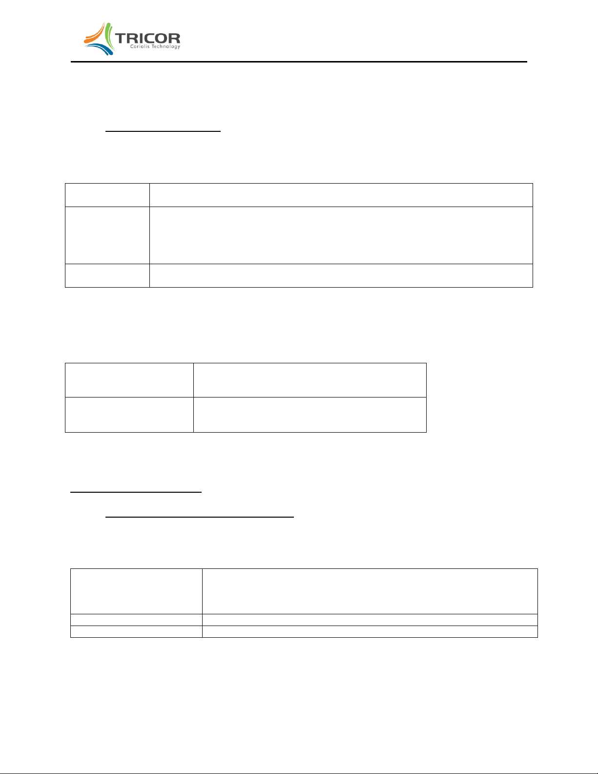
and the following screen will be displayed:
Press the “UP” softkey to display user code of 2207 then press the “P” key to access the SETUP
MENU. There are several submenus in the SETUP MENU, they are:
PARAMETER
Allows setup of various metering parameters.
FILTER
Allows programming of FLOW and DENSITY
filters.
IN/OUTPUTS
Allows programming of the various I/O terminal
functions.
DATA
CONFIGURATION
Allows saving and restoring of the configuration
memory.
RESET TOTAL
Allows zeroing of the grand total and batch total.
PARAMETER programming
When PARAMETER is displayed press the “P” key to access the PARAMETER submenu which
contains the following parameters:
METER MODE
Allows selection of MASS METER or VOLUME
METER
*ENTER USER_CODE*
2206
LEFT UP EXIT

©2011 AW-Lake Company. All rights reserved. All trademarks are the property of their respective holders and are hereby acknowledged. TCE-8000PG-012011 Page | 11
TCE-8000 Transmitter Programming Guide
CUTOFF
Set the value of a low flow cutoff as a percent of
the full scale rating of the flow sensor.
STEP RESP.
Set the value of the step response as a percent
of the full scale flow rating of the sensor.
RESET KEY
Activate (ON) or deactivate (OFF) the “Reset”
for the displayed BATCH TOTAL.
FLOW-DIREC
Define the flow direction through the sensor as
either FORWARD (in the same direction of the
arrow on the flow sensor) or REVERSE (in the
opposite direction of the arrow on the flow
sensor).
K-FACTOR
Default K-FACTOR (also known as meter
factor) is 1.000. Adjusting this value
proportionally will alter the meter output flow
function by that proportion.
FAULT TIME
The time in seconds after a fault is detected
before it is declared as an error.
LANGUAGE
Select the language used on the display.
METER MODE programming
The METER MODE submenu allow selection of MASS METER when the application requires mass units
of measure for both flow rate and flow totals or VOLUME METER when the application requires volume
units of measure for both flow rate and flow totals. When VOLUME METER is selected the volume is
determined by dividing the measured mass by the measured density.
CUTOFF programming
CUTOFF is a low flow cutoff. Because the meter at zero flow has a live zero, that is, there is some
residual amount of noise being measured at zero flow, there will be some small amount of flow noise
being displayed when the flow is actually zero. To avoid this problem which can cause confusion, a cutoff
must be in place so that any detected flow noise below this cutoff is displayed as zero flow rate and the
totalizer is stable and not counting. Ideally, the cutoff should be as low as possible to assure that the
least amount of flow is missed when true flow starts up or shuts off. CUTOFF is programmed as a
percentage of the maximum flow rate for the meter and can be set to a minimum of 0.1% (or higher if
necessary). For example, the TCM28K meter is rated at a maximum flow rate of 28000 kilograms per
hour. Therefore, a CUTOFF setting of 0.1% would mean that any flow below 0.001 x 28000 = 28
kilograms per hour would not be registered. The amount of CUTOFF needed for stable zero indication
may be installation dependent. Enter the lowest value of CUTOFF to obtain a stable zero flow reading.
STEP REPONSE programming
STEP RESPONSE works in conjunction with the FLOW FILTER in that, if a rapid change in flow rate
above the amount specified in the STEP RESPONSE occurs, the filter is temporarily cancelled and the
meter output goes rapidly to the new flow rate value.
In a few applications, it is desirable to have a very stable flow rate displayed when flow is constant
thereby dictating a longer time constant in the FLOW FILTER (e.g. greater than 4 seconds). However, in
this case if STEP RESPONSE is not employed and the actual flow rate makes a rapid step, the meter

©2011 AW-Lake Company. All rights reserved. All trademarks are the property of their respective holders and are hereby acknowledged. TCE-8000PG-012011 Page | 12
TCE-8000 Transmitter Programming Guide
outputs will be slow to respond to it.
In most cases it is more desirable to keep the FLOW FILTER at a low value (e.g. 1 second or less) and
accept a little variation in the flow rate display by deactivating the STEP RESPONSE entirely. The
default value for STEP RESPONSE is therefore deactivated. It is recommended that TRICOR customer
support be consulted before STEP RESPONSE is activated and employed.
RESET KEY programming
The “Reset” key on the display can be programmed to either ON or OFF. When programmed to be ON,
the displayed BATCH TOTAL can be reset to zero by pressing this key at any time. If it is undesirable to
have a local reset then change RESET KEY to OFF. Note that the CONTROL INPUT line can be
programmed for a remote BATCH TOTAL reset.
FLOW DIRECTION programming
The TRICOR meter is bidirectional. That is, the sensor is fully symmetrical and can be installed in the
flow line in either orientation independent of the FLOW symbol on the label. The arrow
indicates the direction of FORWARD flow in the software configuration. If the sensor is installed in the
opposite orientation simply change FLOW DIRECTION to REVERSE in order to show positive numbers
in both the FLOW RATE and BATCH TOTAL.
Note that flow in the opposite direction will indicate negative values of FLOW RATE and the BATCH
TOTAL will decrement rather than increment. If the BATCH TOTAL decrements down to zero and
continues on down, it will show negative numbers in the BATCH TOTAL.
K-FACTOR programming
The meter calibration can be changed in one of two ways. The first is to change the “factory calibration
factor” known as METER VARIABLE which is accessed under the SERVICE menu. A more convenient
recalibration method is to modify the K-FACTOR (while preserving the factory calibration factor). The
default K-FACTOR is 1.00000. Increasing the K-FACTOR will increase the meter output. Conversely,
decreasing the K-FACTOR will decrease the meter output.
EXAMPLE: A field recalibration is performed using a calibrated weight scale. The meter registers 105.62
pounds and the weight scale registers 105.51 pounds. The meter is high by 0.104%. Recalculate the K-
FACTOR as follows:
(old K-FACTOR) X (scale ÷ meter) = new K-FACTOR
(1.00000) x (105.51 ÷ 105.62) = 0.99896. Change the K-FACTOR to 0.99896 to improve the meter
accuracy.
FAULT TIME programming
Should an error be detected by the meter electronics it may be desirable to delay the declaration of it in
order to not disrupt the operation of the meter, especially if the error is short lived such as an air bubble
passing through the meter causing a temporary reduction in amplitude of the Coriolis sensors. The
default is 2.7000 seconds delay and should suffice for most applications but can be increased or reduced
as needed.
LANGUAGE programming
The default language on the display is ENGLISH but can be changed to others as they become available.
©2011 AW-Lake Company. All rights reserved. All trademarks are the property of their respective holders and are hereby acknowledged. TCE-8000PG-012011 Page | 13
TCE-8000 Transmitter Programming Guide
FILTER programming
When FILTER is displayed press the “P” key to access either the FLOW FILTER or the DENSITY FILTER
by pressing the UP or DOWN key. Enter the “time constant” for the filter selected. The time constant is
defined as the time in seconds that is required to reach 63% of the final value after a step change in the
actual flow or density. The filter used is a software representation of a classical single pole RC filter used
in analog electronics.
IN/OUTPUTS programming
When IN/OUTPUTS is displayed press the “P” key to access the IN/OUTPUTS submenu which
contains the following I/O terminals:
FREQ OUT
Scaling of flow pulses on f-out (terminals #5 to 8)
CTRL OUT
Definition of the function of digital control output (terminals
#6 to 8).
ANALOG OUT
Scaling of analog 1 output (terminals #1 to 2)
Scaling of analog 2 output (terminals #3 to 4)
CTRL IN
Definition of the function of digital control input (terminals
#7 to 8).
INTERFACE
Definition of communications interface used
FREQ-OUT programming
With FREQ-OUT displayed, press the “P” key to bring up the current function of the f-out output of the
transmitter. Press the “Up” or “Down” key to select the desired function from the list below:
FREQ-OUT
Description
FREQUENCY
f-out produces a frequency that is proportional to the flow rate. Frequencies up to
10,000 Hz can be produced in the FREQUENCY mode of operation. Note:
Because this mode outputs a frequency proportional to flow rate, totalizing these
pulses may result in a slight discrepancy from the TOTAL display.
TOTAL COUNT
f-out produces pulses that are based on the internal totalizer. In the TOTAL
COUNT mode, a change in state from low to high, or high to low occurs when the
internal totalizer increases by a set amount of mass (or volume). Totalizing these
pulses results in an accurate representation of the TOTAL display. The maximum
output in this mode is about 15 pulses per second.
FREQUENCY programming
After selecting FREQUENCY mode of operation, press the “P” key to view and/or set the additional
scaling parameter required for the frequency mode of operation. In each of the following screens set the
numerical value using the “RIGHT” and “UP” keys, then “P” to advance to the next parameter.
FULL SCALE FLOW
Flow rate in the FLOW-UNITS selected that correspond to the
frequency selected in the next screen, FULL SCALE FREQUENCY.
FULL SCALE FREQUENCY
Frequency corresponding to the flow rate entered in the previous
screen, FULL SCALE FLOW.

©2011 AW-Lake Company. All rights reserved. All trademarks are the property of their respective holders and are hereby acknowledged. TCE-8000PG-012011 Page | 14
TCE-8000 Transmitter Programming Guide
Example 1: The application is expected to reach a full scale flow rate of 600 pounds per minute. The
display totalizer is set to display BATCH TOTAL to 0.001 pound resolution and it is desired to have the
external pulse counter have the same resolution, 1 pulse per 0.001 pound. The FULL SCALE
FREQUENCY is entered in Hz which is equivalent to pulses per second but the flow rate is expressed in
pounds per minute. Perform the following calculation.
600 pounds / minute ÷ 60 seconds per minute = 10 pounds per second
10 pounds per second ÷ 0.001 pulses / pound = 10000 pulses per pound = 10000 Hz
Therefore:
FULL SCALE FLOW = 600.00 lbs/min
FULL SCALE FREQUENCY = 10000 Hz
Example 2: The application is expected to reach a full scale flow rate of 36000 pounds per hour. The
display totalizer is set to display BATCH TOTAL to 0.01 pound resolution and it is desired to have the
external pulse counter have the same resolution, 1 pulse per 0.01 pound. The FULL SCALE
FREQUENCY is entered in Hz which is equivalent to pulses per second but the flow rate is expressed in
pounds per hour. Perform the following calculation.
36000 pounds /hour ÷3600 seconds per hour = 10 pounds per second
10 pounds per second ÷ 0.01 pulses / pound = 1000 pulses per pound = 1000 Hz
Therefore:
FULL SCALE FLOW = 36000.0 lbs/hr
FULL SCALE FREQUENCY = 1000 Hz
TOTAL COUNT programming
After selecting the TOTAL COUNT mode of operation, press the “P” key to view and/or set the SELECT
VALUE in total units to the value for each output pulse. To ensure that the TOTAL COUNT output does
not exceed the maximum frequency of 15 Hz, the SELECT VALUE must be checked against the
maximum flow rate expected or a delay of the pulses out could result.
Press the “P” key to return to FREQ-OUT display.
Example : The application is expected to reach a full scale flow rate of 600 pounds per minute. The
TOTAL COUNT mode of operation is selected to produce a low frequency pulse output. One pulse per
0.1 pound is to be sent to an external PLC device. SELECT VALUE is set to 0.1000 POUNDS. Perform
the following calculation to verify that at the maximum flow rate of 600 pounds per minute the pulse output
will not exceed 15 Hz.
600 pounds per minute ÷ 60 seconds/minute = 10 pounds per second
10 pounds per second ÷ 0.1 pounds per pulse = 100 pulses per second = 100 Hz
©2011 AW-Lake Company. All rights reserved. All trademarks are the property of their respective holders and are hereby acknowledged. TCE-8000PG-012011 Page | 15
TCE-8000 Transmitter Programming Guide
This exceeds the maximum frequency of 15 Hz which is a limitation of the TOTAL COUNT functionality
and, therefore, will not work properly. The SELECT VALUE could be increased to 1.0 pounds per pulse
in order to reduce the maximum frequency to 10 Hz which does not exceed the 15 Hz limit.
CNTL OUT programming
When CNTL OUT is displayed press the “P” key to select the function of the Control Output terminal #6
with respect to #8.
FAULT
Control output goes from low to high when a fault is declared.
FREQ OUT DIR
If the application requires bi-directional flow through the meter the Control Output can
be set to indicate the direction of flow through the meter so that the frequency output
can be qualified to be FORWARD FLOW (Control Output low) or REVERSE FLOW
(Control Output high).
BATCH
The Control Output can be used to control a batch control valve.
If BATCH is selected the Control Input terminal must previously have been programmed to RESET
BATCH as a start switch for the batch control function. Additionally, two more parameters must be
programmed:
BATCH VALUE
Enter the preset amount of the batch to be
delivered each start cycle.
SELECT OUTPUT LEVEL
ACTIVE LOW (a low signal when not flowing)
ACTIVE HIGH (a high signal when not flowing)
Press the “P” key to return to CNTL OUT display.
ANALOG OUT programming
ANALOG 1 (or ANALOG 2) programming
With ANALOG 1 (or ANALOG 2) displayed, press the “P” key to view and/or set the additional scaling
parameter required for each milliamp output.
SELECT OUTPUT MODE
FLOW
DENSITY
TEMPERATURE
BATCH COUNT
VALUE AT 4 mA
The value of the process variable selected at 4 mA.
VALUE AT 20 mA
The value of the process variable selected at 20 mA
The milliamp outputs can be freely programmed to set 4 mA at one value and 20 mA at another value for
the measured variable selected.
Press the “P” key to return to ANALOG 1 (or ANALOG 2) display.

©2011 AW-Lake Company. All rights reserved. All trademarks are the property of their respective holders and are hereby acknowledged. TCE-8000PG-012011 Page | 16
TCE-8000 Transmitter Programming Guide
CNTL IN programming
When CNTL IN is displayed press the “P” key to select the function of the Control Input terminal #7 with
respect to #8.
EXT. ZERO
Initiate a ZERO OFFSET procedure using an external high signal into terminal 7
RESET BATCH
Reset the BATCH TOTAL from an external high signal into terminal 7 and/or start a
batch using the Control Output programmed to BATCH.
Press the “P” key to return to CNTL IN display.
INTERFACE programming
When INTERFACE is displayed press the “P” key to select the function of the digital communication
interface that will be serviced by the software configuration from the interface submenu below:
RS485
Communicate over the RS485 terminals 20, 21, and 22 using the TRICOR protocol. If RS485 is
selected an additional screen to set the node address will be displayed. The default node
address is 01.
HART
Communicate over ANALOG 2 terminals using the HART protocol
FF
Communicate over the Foundation Fieldbus terminals 30 and 31 using the Foundation Fieldbus
protocol
.
Press the “P” key to return to the INTERFACE display.
DATA CONFIGURATION programming
When DATA CONFIGURATION is displayed the EEPROM memory can be accessed to either SAVE
DATA as currently configured to EEPROM memory or RECALL DATA from the EEPROM memory.
SAVE DATA programming
With SAVE DATA displayed, you can save all new configuration settings in the non-volatile EEPROM
memory. If you made changes but have not saved them, a warning message appears during startup for
about 10 seconds as follows:
To initiate a SAVE DATA operation, press the “P” key and the following screen will appear:
***… WARNING…***
THERE IS NO RAM BACKUP
LOOK INTO YOUR MANUAL
PRESS ENT TO CONTINUE

©2011 AW-Lake Company. All rights reserved. All trademarks are the property of their respective holders and are hereby acknowledged. TCE-8000PG-012011 Page | 17
TCE-8000 Transmitter Programming Guide
Press “START” and the following screens will appear:
RECALL DATA programming
With RECALL DATA displayed, you can delete any changes that have been made to revert to the settings
the last time SAVE DATA was performed. To initiate a RESTORE DATA operation, press the “P” key and
the following screen will appear:
Press the “START” softkey and the following screens will appear:
I/O –TEST programming
With I/O TEST displayed, you can drive the Frequency, Analog 1 and 2, or Control Outputs to fixed levels
to test your receiving device(s). You can also test the level of the Control Input being received. The I/O
TEST submenu is as follows:
FREQ OUT
Produce a fixed frequency (terminals #5 to 8).
CTRL OUT
Produce a low or high level (terminals #6 to 8).
ANALOG OUT
Produce a fixed current level on Analog 1 (terminals #1 to 2) or Analog 2 (terminals #3
to 4)
CTRL IN
Read back the status of the Control Input on terminals #7 to 8
READY TO SAVE DATA
START EXIT
MEMORY
ACCESS
READY
RESTORE BACKUP DATA
START EXIT
MEMORY
ACCESS
READY
©2011 AW-Lake Company. All rights reserved. All trademarks are the property of their respective holders and are hereby acknowledged. TCE-8000PG-012011 Page | 18
TCE-8000 Transmitter Programming Guide
FREQ OUT programming
With FREQ OUT selected, press the “P” key to ENTER FREQUENZ [HZ]. Valid entries are 1 to 9999 Hz.
Press the “P” key and the frequency that was displayed will be output while the display reads as follows:
Press “YES” to enter a different frequency or “EXIT” to stop the test.
CTRL OUT programming
With CTRL OUT selected, press the “P” key. When SELECT OUTPUT LEVEL is displayed select either
HIGH or LOW.
Press “EXIT” to return to CTRL OUT
ANALOG OUT programming
With ANALOG OUT displayed press the “P” key. OUTPUT 1 or OUTPUT 2 can be selected using the
“UP” or “DOWN” softkey.
With OUTPUT n selected, press the “P” key to ENTER CURRENT n [mA]. Valid entries are 1 to 22 mA.
Press the “P” key and the current that was displayed will be output while the display reads as follows:
Press “YES” to enter a different current or “EXIT” to stop the test. Press “EXIT” again to display I/O -
TEST. Press “EXIT” again to return to the normal display.
CHANGE VALUE
YES EXIT
CHANGE VALUE
YES EXIT


Americas:
8809 Industrial Drive
Franksville, WI 53126 USA
Tel.: 800-850-6110
Europe:
Liebigstraße 2
85757 Karlsfeld, Germany
Tel.:+49 (0)8131 59391-0
Asia:
Rm.2429, JinYuan Ofce Building, No. 36
CN- BeiYuan Road, Beijing 100012
P.R.CHINA
Tel.:+86 10 520 037 38
www.tricorflow.com ©2011 AW-Lake Company. All rights reserved.
Doc ID: TCE8000PROG-100512
Table of contents
Popular Transmitter manuals by other brands


Conrad
Conrad FS20 S8-2 operating instructions

Michell Instruments
Michell Instruments Easidew user manual

Emerson
Emerson Rosemount 2051 Reference manual

Cooper Security
Cooper Security 702r manual

Altinex
Altinex SIGNAL MANAGEMENT SOLUTIONS UT260-105 user guide

Becker
Becker Centronik SunWindControl SWC441 Assembly and operating instructions