Trident RiX-70 DC User manual

User Manual
RiX 70 DC
1
1. INTRODUCTION ....................................... 2
1.1 User Recommendations.................... 2
1.2 Safety Recommendations................ 2
1.3 About your Unit…............................... 3
1.4 Device Classification …………………3
2. TECHNICAL DATA .................................. 4
2.1 System Supply .................................. 4
2.2 X-ray Head ........................................ 4
2.3 X-Ray Tube ……………...................... 4
2.4 Weights ……………………………….. 4
3. OPERATING INSTRUCTIONS ................... 5
3.1 The Control Panel ............................ 5
3.2 Additional Key pad.......................... 5
3.3 Beam Limiting Device …….............. 6
3.4 Operation ........................................ 6
3.5 Pre-set exposure time………………. 7
3.6 Manual selection of exposure time 8
4. CARE AND MAINTENANCE ............................ 8
4.1 Cleaning .................................................... 8
4.2 Disinfecting ................................................ 8
4.3 Maintenance ............................................. 8
5. DISPOSING OF OBSOLETE EQUIPMENT .......... 9
6. ELECTROMAGNETIC COMPATIBILITY ............. 9
6.1 Electromagnetic Emissions ....................... 9
6.2 Electromagnetic Immunity ..................... 10
6.3 Recommended Separation Distances
Between Portable and Mobile RF
Communication Equipment and
RiX-70DC ……………………………………….... 11
Appendix A Systems ......................................... 12
Appendix B Icons ............................................... 14
Appendix C Heating and Cooling Curves...... 15
Appendix D Alarms ……………......................... 16
Appendix E Labels ............................................. 18
This is an English translation of the original document in Italian which may be obtained
from the company.
The content of this document is faithful and accurately reflects the original version.
Castenedolo, 2017.
TABLE OF CONTENTS

User Manual
RiX 70 DC
2
1 Introduction
Thank you for trusting our company and choosing RiX-70 DC as your Intraoral X-Ray System.
This manual, supplied with the system, is an integral part of the product; please keep it close to the
unit’s installation location; it describes the parts and components of your RiX-70 DC and explains the
correct operation of the unit by observing all the relevant safety measures when handling X-ray
equipment. The original language of the User Manual is Italian.
1.1 User Recommendations
Carefully read and follow the warnings and safety instructions contained in the
User’s Manual.
Use the device in accordance with the procedures explained in the present
manual, and do not use it for purposes other than those it was designed for.
Failure of the user to properly maintain the equipment may relieve Trident or his
dealer, from responsibility for any injury, damage, or non-compliance, which
may result.
Report promptly to Trident or to its dealer any accident involving this device or
any alteration in features and/or performances which could cause death,
injuries or health hazard to Patient and/or Operator.
1.2Safety Recommendations
Carefully read all the safety instructions to avoid potential hazards that could result in personal
injuries or could damage your equipment.
This table contains important information regarding the system, the operator
and the patient safety.
Please read this table very carefully.
RiX-70 DC is an electro-medical device that must be used under the supervision
of a doctor or a person with vast experience in radiology.
Do not modify the device mechanically and / or electrically during or after the
installation.
RiX-70 DC is built for continuous operation with intermittent load; therefore, it is
required to observe the cycles of use allowing the dissipation of heat
accumulated by the radiation source.
RiX-70 DC must be switched off when using electro surgery or similar devices.
Make sure the installation of your X-Ray unit is carried out only by qualified
personnel. Absolutely avoid provisional electrical connections and verify that
only the parts (screws, nuts, bolts, etc.) recommended by the manufacturer are
used.
The installation area must comply with the current regulations pertaining to
radiology in the country of operation.

User Manual
RiX 70 DC
3
Do not drop, knock, or shake the unit: rough handling or use beyond the
recommendations may cause damage to internal circuitry.
The operator should take every reasonable precaution to maintain a safe and
healthy working environment, minimizing the radiation hazard.
During the exposure, make sure no one except the patient and operator are
present in the X-ray area.
In accordance with EN 60601-1, it is strictly forbidden to modify the equipment
or its parts.
Only trained and qualified technicians are authorized to remove the covers
giving access to the circuits.
The cables of the power supply must comply with applicable laws and must be
equipped with terminals for connecting to the protective earth.
Always turn off the machine and unplug it from the mains whenever possible
(with the switch) before cleaning and disinfection.
Carry out a proper cleaning and disinfection of all parts which come into
contact with the patient.
Check regularly (at least once a year) the state of correct operation of the
system by involving a specialist for any maintenance.
Do not use the device in the presence of vapours, or flammable anaesthetic
mixtures with air, or oxygen or nitrous oxide.
When using digital sensors, if the PC is positioned within the patient environment,
it must meet the requirements defined by the IEC 60601-1 medical device; if
located outside it must be in compliance with IEC 60950. The size of the patient
environment is defined as a minimum distance of 1.5 m from the patient.
1.3About your unit
RiX-70 DC is an intraoral X-ray system that emits ionizing radiation, X Ray, for taking images of the
oral cavity. RiX-70 DC with a high technological development allows getting high quality images
using both normal films and digital images receptors (intraoral sensor and phosphor plates). This
system has two version, wall mounted and mobile.
1.4Device Classification
RiX-70 DC is a Class I device, Type B, conforms to IEC 60601-2-65: 2012. RiX-70 DC, according to the
classification rules set out in Annex IX of EC Directive 93/42 and its amendments and supplements,
is an active medical device that releases energy (ionizing radiation X Ray) and represents a
potential hazard to the human body.

User Manual
RiX 70 DC
4
2. TECHNICAL DATA
2.1 System Supply
Voltage
AC100-240 V
Frequency
50/60 Hz
Electric current
2-1 A(@240V), 5.5 A (@110V)
Max power consumption
640 VA
Fuse
6.3 AT
Connection
7 wires cable with double insolation
2.2 X-Ray Head
Tube Voltage
60 kVp ± 8 %
65 kVp ± 8 %
70 kVp ± 8 %
Anode current
7 mA± 10 %
Output radiation linearity
< 0.2 secondo IEC 60601-2-63
Duty cycle
1:30
Nominal power
490 W (70 kVp - 7 mA)
Total filtration
1.5 mm Al eq. @ 70 kVp
Current transformer insulation
Oil bath
Cooling
As per convention
Focal spot
0.4 mm (IEC 60336)
Leakage radiation at 1 m
< 1 mGy/h
Max thermal capacity of monoblock
130 kJ
Distance focus to skin
20 cm
Beam diameter X Ray at 200 mm focus
60 mm
Bean limiting device (additional)
Rectangular 36 x45 mm
Dose intensity accuracy
< 50%
2.3 X-Ray Tube
Manufacturer
Toshiba(Japan)
CEI(Italy)
Model
D-045
OX70-4
Inherent filtration
< 1 mm Al eq.
0.5 mm Al eq.
Target angle
12.5°
16°
Filament current
Max. 3 A
1.5 –2.1 A
Max filament current
3 V
1.7 –3.1 V
Anodic thermal capacity
4.3 kJ
7 kJ
Max anodic dissipation
100 W
110 W
X RAY beam covering at 200 mm from the focus
70 mm
Focal spot
0.4 IEC 60336:2005
Target material
Tungsten
Max nominal voltage
70 kV
2.4 Weights
Timer
4.00 kg
Support arm 60 cm
1.7 kg
Support arm 80 cm
4.5 kg
Support arm 100 cm
5.5 kg
Scissor arm
11.4 kg
Tube head
4.3 kg
Mobile stand base
24 kg
Mobile stand column
4.00 kg
Wall mounted version with 80 cm arm support
25 kg
Mobile version
45 kg
Package
112 x 36 x h32.5 cm Weight: 27 kg

User Manual
RiX 70 DC
5
3. OPERATING INSTRUCTIONS
3.1 The Control Panel
Emission in progress(yellow light ON)
Alarm(red light ON), the system has a problem, CAUTION. It can cause the
interruption of the emission.
Buttons to manually increase/ decrease the preset values.
Menu, pressing this button for at least 2s allows to access the User’s Menu. This menu contains
the parameters that do not need to be adjusted frequently. To exit the user’s menu it’s necessary
to push again “Menu” button.
X RAY button Activation, pressing this button will be activated on the display a count down during
which you can make expositions by pressing the X Ray button.
Tooth Type selection, choose the tooth to be examined: lower incisors , lower canines, lower
bicuspids, lower molars, upper molars, bicuspids, upper canines, upper teeth, bitewing.
System ready (green light ON)
kV selection, allows to select the voltage from 60, 65 and 70 kVp
Image receptor selection, select the receptor from film, intraoral sensor and phosphor plate.
Patient size selection, according to patient morphology choose between adult or child.

User Manual
RiX 70 DC
6
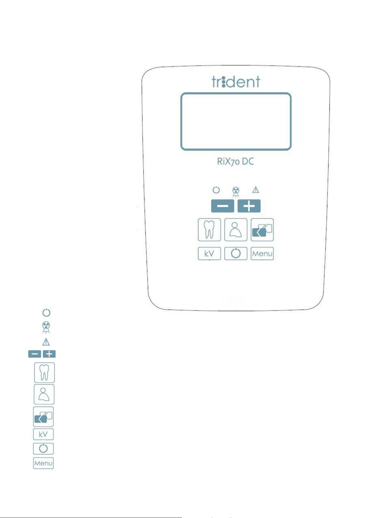
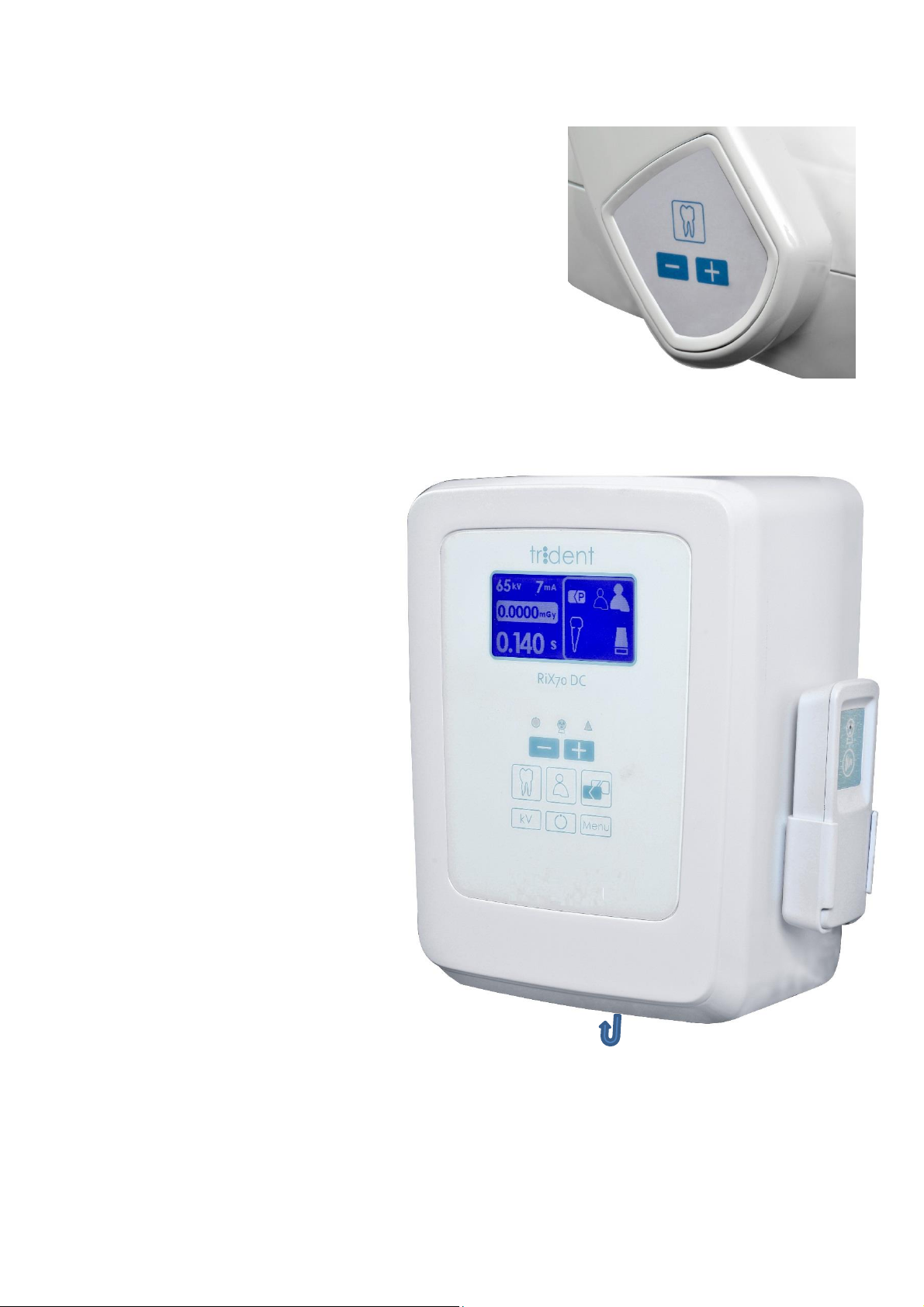
3.2 Additional keypad
The system has an additional keypad installed near the tube
head, which allows to adjust the exposure time, tooth type
and patient size.
3.3 Beam Limiting Device
This device is suitable for either bisecting or paralleling
radiographic techniques, once conveniently angled. Keep
the rim of the collimator in touch with the film holder or with
the face of the patient to reduce possible blur due to
movement during irradiation.
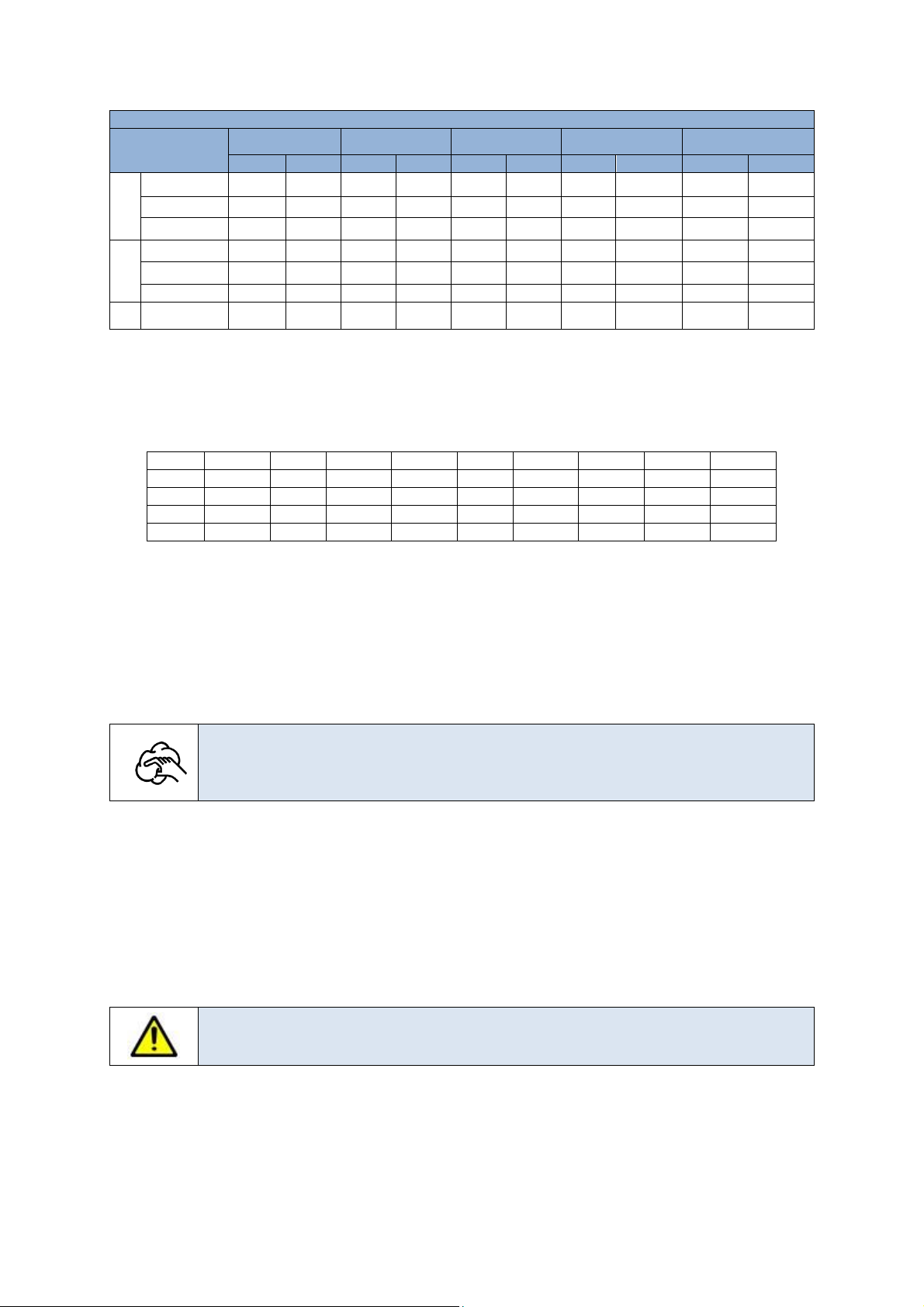
3.4 Operation
Turn on the device with the switch below the timer. Immediately an automatic auto-diagnosis will
be displayed. The software version is shown. At the end of the autodiagnosis procedure, the display
will show the exposure parameters of the last exposition.
1. Pressing the kVp button select the
kVp from 60, 65 or 70 according to
your needs.
2. Select the image receptor from
film, intraoral sensor or phosphor
plate: touch the symbol "Image
Receptor Selection" to make your
choice and the display will show
the symbol of your selection; in the
case of analog receptor, it is also
indicated the sensitivity of the
selected film.
3. Select the patient size and type of
tooth.
Tooth type: touch the symbol
corresponding to the tooth you
want to x-ray; the display will
show the symbol corresponding
to the selection.
Once you select these parameters, RiX-
70 DC automatically selects the output
time for the type of X-Ray to be
performed; the exposure time will
appears on the display, whether you
need increase or decrease it, use the
"+" or "-" buttons.
When you manually change the exposure time, the information of the parameters that had
contributed to calculate that time will disappear from the display; tapping again one of the
parameter’s symbol, the system will return to that exposure time.
Every time a parameter is changed, the system recalculates the appropriate exposure time; the
display shows the exposure time and the estimated air absorbed dose in μGy, delivered to patient.
Patient size: touch the symbol for
the patient size (large, small); the
display will show the symbol
corresponding to the selection.
1A Yellow light
1B Yellow light
2 Exposure pushbutton
3 Line-Switch On/Off below the unit
1A
1B
2
3

User Manual
RiX 70 DC
7
4. Place the patient, who must wear the appropriate protective lead apron (not supplied by Trident
Dental), in the right position.
5. Position the image receptor where needed and orientate the tube-head accordingly. Operate
with the edge of the collimator in contact with the ring of the centering film (optional, not
provided) or with the patient's face.
6. Take the exposure hand-switch and move to a convenient position of at least 2 m far from the
patient.
7. Press the exposure pushbutton. The yellow light indicates X-ray emission. Keep the exposure
pushbutton pressed until the yellow light are switched OFF to indicate the end of the exposure.
8. Hook back the exposure hand-switch and process the image receptor exposed.
Warning
If the exposure pushbutton is released before the end of the requested time, the
radiation emission is terminated and an alarm is generated.
To use the rectangular collimator it’s necessary to select the right setting from the
User’s Menu
3. 5 Pre-set exposure time
RiX70 DC calculate exposure times as per the following tables:
CAUTION
The following values, set as default values, are based on the quality image
evaluation. The effective set of those values depends on many aspects as per
the user preference (contrast, brightness etc..) and per patient mouth anatomy.
70 kV
Tooth/Patient
size
Digital sensor
Film type D
Film type E
Film type F
Phosphor system
Adult
Child
Adult
Child
Adult
Child
Adult
Child
Adult
Child
Maxilla
Molars
0.100
0.063
0.320
0.200
0.125
0.080
0.100
0.063
0.320
0.200
Premolars
0.080
0.050
0.250
0.160
0.100
0.063
0.080
0.050
0.250
0.160
Incisors
0.063
0.032
0.200
0.125
0.080
0.050
0.063
0.040
0.200
0.125
Mandible
Incisors
0.056
0.020
0.125
0.080
0.050
0.032
0.040
0.025
0.125
0.080
Premolars
0.063
0.036
0.160
0.100
0.063
0.040
0.050
0.032
0.160
0.100
Molars
0.080
0.050
0.250
0.160
0.100
0.063
0.080
0.050
0.250
0.160
Bitewing
0.100
0.063
0.400
0.250
0.160
0.100
0.125
0.080
0.400
0.250
65 kV
Tooth/Patient
size
Digital sensor
Film type D
Film type E
Film type F
Phosphor system
Adult
Child
Adult
Child
Adult
Child
Adult
Child
Adult
Child
Maxilla
Molars
0.125
0.071
0.450
0.320
0.180
0.125
0.160
0.110
0.450
0.320
Premolars
0.100
0.063
0.360
0.250
0.160
0.110
0.125
0.090
0.360
0.250
Incisors
0.080
0.040
0.320
0.220
0.125
0.090
0.100
0.071
0.320
0.220
Mandible
Incisors
0.063
0.025
0.180
0.125
0.071
0.050
0.063
0.045
0.180
0.125
Premolars
0.090
0.045
0.250
0.180
0.090
0.063
0.080
0.056
0.250
0.180
Molars
0.100
0.063
0.360
0.250
0.160
0.110
0.125
0.090
0.360
0.250
Bite-wing
0.160
0.100
0.630
0.360
0.250
0.180
0.200
0.140
0.630
0.360

User Manual
RiX 70 DC
8
60 kV
Tooth/Patient
size
Digital sensor
Film type D
Film type E
Film type F
Phosphor sensor
Adult
Child
Adult
Child
Adult
Child
Adult
Child
Adult
Child
Maxilla
Molars
0.200
0.125
0.630
0.400
0.250
0.160
0.200
0.125
0.630
0.400
Premolars
0.160
0.100
0.500
0.320
0.200
0.125
0.160
0.100
0.500
0.320
Incisors
0.125
0.063
0.400
0.250
0.160
0.100
0.125
0.080
0.400
0.250
Mandible
Incisors
0.110
0.040
0.250
0.160
0.100
0.063
0.080
0.050
0.250
0.160
Premolars
0.125
0.071
0.320
0.200
0.125
0.080
0.100
0.063
0.320
0.200
Molars
0.160
0.100
0.500
0.360
0.200
0.125
0.160
0.100
0.500
0.360
Bite-wing
0.200
0.125
0.800
0.500
0.320
0.200
0.250
0.160
0.800
0.500
3.6 Manual selection of Exposure time
The user can manually modify the pre-set exposure times for any type of receptor, pressing one of
the buttons “+” or “-“ from the main keyboard or on the optional keyboard. Times can move of 47
steps from 0.010 to 2s as per the following table:
0.010
0.011
0.012
0.014
0.016
0.018
0.020
0.022
0.025
0.028
0.032
0.036
0.040
0.045
0.050
0.056
0.063
0.0710
0.080
0.090
0.100
0.110
0.125
0.140
0.160
0.180
0.200
0.220
0.250
0.280
0.320
0.360
0.400
0.450
0.500
0.560
0.630
0.710
0.800
0.900
1.000
1.100
1.250
1.400
1.600
1.800
2.000
4 CARE AND MAINTENANCE
4.1 Cleaning
Always disconnect the line voltage supply before cleaning the unit. Use a mild soap to remove fin-
ger or other dirty marks paying attention not to have liquids enter into the equipment.
Clean painted surfaces , accessories and connection cables only by hand with
a damp cloth and mild detergent, making sure to wipe with a dry cloth ; Do not
use solvents ( alcohol, benzene , trichlorethylene ), corrosive and abrasive.
4.2 Disinfecting
Parts in touch with the patient must be cleaned with a detergent (such as 2% solution of ammonia)
making sure not to use solvents or corrosive disinfectants, which can cause cracks on the plastic
covers.
4.3 Maintenance
Maintenance of RiX- 70 DC to be done regularly by a service technician at least once every 24
months, in addition to regular checks performed by the operator every year.
RiX-70 DC system not contain parts that can be repaired by the user.
The system must be opened and maintained by qualified personnel.

User Manual
RiX 70 DC
9
5. DISPOSING OF OBSOLETE EQUIPMENT
A radiological system is made of different materials which include many kinds of
metals (iron, aluminum, lead, copper and others), plastic materials, electronic
components and dielectric oil in the tank of the X-ray tube. The "crossed-out wheeled
bin" symbol on the product indicates that the product at the end of its useful life must
not be disposed of as unsorted municipal waste but has to be collected separately
and delivered to specialized operators for recycling or disposal of waste of electrical
and electronic equipment (WEEE), in compliance with existing laws.
6. ELECTROMAGNETIC COMPATIBILITY
Medical electrical equipment needs special precautions regarding EMC and needs to be
installed and put into service according to electromagnetic emissions information
provided in this manual.
RiX-70 DC meets the requirements of IEC 60601-1-2 concerning the
electromagnetic emissions. It is suitable for use in the electromagnetic
environment that meets the conditions described below.
6.1 Electromagnetic Emissions
The device may cause radio interference and may disrupt the operation of
nearby equipment. It may be necessary to take mitigation measures, such as
re-orienting or relocating the equipment, or shielding the location.
The system comes with all the cables needed for its operation. Using other
cables not supplied by the manufacturer or in addition to those provided by
the manufacturer can significantly influence the electromagnetic behaviour
of RiX-70 DC. It may result in increased emissions or decreased immunity of the
device.
Emission test
Compliance
Electromagnetic Environment—Guidance
RF (Radio Frequency)
Emissions CISPR 11
Group I
The device uses RF energy only for its internal function.
Therefore, its RF emissions are very low and are not
likely to cause any interference in nearby electronic
equipment.
RF (Radio Frequency)
Emissions CISPR 11
Class B
The device is suitable for use in all establishments other
than domestic, and in those directly connected to the
public low-voltage network that supplies buildings
used for domestic purposes.
Harmonic Emissions
IEC 61000-3-2
Not applicable
Not applicable
Voltage fluctuation /
flicker IEC/EN 61000-3-3
Not applicable
Not applicable

User Manual
RiX 70 DC
10
6.2 Electromagnetic Immunity
Immunity test
IEC60601 1-1-2 Test Level
Compliance level
EMC environment guidance
Electrostatic discharge
(ESD) IEC 61000-4-2
± 6 kV contact
± 8 kV air
Test level IEC
60601-1-2
Floors should be wood, concrete or
ceramic tile. If floors are covered with
synthetic material, the relative
humidity should be at least 30 %.
Electrical fast transient/
burst IEC 61000-4-4
±2 kV for power supply
lines
±1 kV for input/output
lines
Test level IEC 60601-
1-2
Mains power quality should be that of
a typical commercial or hospital
environment.
Surge IEC/EN61000-4-5
± 1 kV differential mode
± 2 kV common mode
Test level IEC 60601-
1-2
Mains power quality should be that of
a typical commercial or hospital
environment.
Voltage dips, short
interruptions and voltage
variations on power
supply input lines
IEC 61000-4-11
<5% Ut (>95% dip in Ut)
for 0.5 cycle
40% Ut (60% dip in Ut)
for 5 cycles
70% Ut (30% dip in Ut)
for 25 cycles
<5% Ut (>95% dip in Ut)
for 5 sec
Test level IEC 60601-
1-2
Mains power quality should be that of
a typical commercial or hospital
environment.
If the user of the device requires
continued operation during power
mains interruptions, the device needs
to be powered from an uninterruptible
power source.
Power frequency
(50/60Hz) magnetic field
IEC 61000-4-8
3 A/m
Test level IEC 60601-
1-2
Power frequency magnetic fields
should be at levels characteristic of a
typical location in a typical
commercial or hospital environment.
Conducted RF
IEC 61000-4-6
3 Vrms
150 kHz to 80 MHz
3Vrms
Portable and mobile RF
communications equipment should
be used no closer to any part of the
device, including cables, than the
recommended separation distance
calculated from the equation
applicable to the frequency of the
transmitter.
Recommended separation distance
d = 1,2 √P 80 MHz to 800 MHz
d = 2,3 √P 800 MHz to 2.5 GHz
d = 1,2 √P
Where (P) is the maximum output
power rating of the transmitter in watts
(W) according to the transmitter
manufacturer and (d) is the
recommended separation distance in
meters (m).
Field strengths from fixed RF
transmitters, as determined by an
electromagnetic site survey, should
be less than the compliance level in
each frequency range.
Radiated RF
IEC 61000-4-3
3 Vrms
80 MHz to 2.5 GHz
3 V/m
Interference may occur in the vicinity of equipment marked with this symbol

User Manual
RiX 70 DC
11
6.3 Recommended Separation Distances Between Portable and Mobile RF Communication
Equipment and RiX-70DC.
RiX-70 DC is intended for use in an environment in which radiated RF disturbances are
controlled. The user of the device can help prevent electromagnetic interference by
maintaining a minimum distance between portable and mobile RF communications
equipment (transmitters) and the device as recommended below, according to the
maximum output power of the communications equipment.
Rated maximum
output power of
transmitter (W)
Separation distance according to frequency of transmitter (m)
150 kHz to 80 MHz
d = 1,2 √P
80 MHz to 800 MHz
d = 1,2 √P
800 MHz to 2.5 GHz
d = 2,3 √P
0.01
0.12
0.12
0.23
0.1
0.38
0.38
0.73
1
1.2
1.2
2.3
10
3.8
3.8
7.3
100
12
12
23
For transmitters rated at a maximum output power not listed above, the recommended separation
distance din metres (m) can be determined using the equation applicable to the frequency of the
transmitter, where Pis the maximum output power rating of the transmitter in watts (W) according
to the transmitter manufacturer.
At 80 MHz and 800 MHz, the separation distance for the higher
frequency range applies.
These guidelines may not apply in all situations. Electromagnetic
propagation is affected by absorption and reflection from structures,
objects and people.

User Manual
RiX 70 DC
12
Appendix A
Systems
1
2
7
6
3
4
5
8
Walll mounted version
1 Wall plate
2 Support arm (40/60/ 80 cms)
3 Scissor arm
4 Monoblock Support (tie)
5 Monoblock
6 Cone (collimator)
7 Control panel (timer)
8 Handswitch with cable

User Manual
RiX 70 DC
13
Stand mobile version
1 Mobile stand base
2 Mobile stand column
3 Control unit (timer) + hand switch with
cable
4 Scissor arm
5 Monoblock with cone collimator
1
2
3
4
5

User Manual
RiX 70 DC
14
Appendix B
Icons
SYMBOL
DESCRIPTION
Device with applied parts of type B. IEC 60601-1 uses the term applied
part to refer to the part of the medical device which comes into physical
contact with the patient in order to carry out its intended function.
The product, at the end of its useful life, can not be thrown in the regular
trash with other wastes and is subject to a separate collection.
Alternating Current
N
Conductor connected to the neutral point
L
Connection point to the Power Line
Grounding
Functional earth connection
ON/OFF
POWER ON
Power OFF
Electric shock risk
Product Reference
Serial Number
Manufacturing date
Manufacturer address
Total Filtration
Monoblock
X RAY Tube
Hand cleaning

User Manual
RiX 70 DC
15
Appendix C
Heating and cooling curves
CEI TUBE
TOSHIBA TUBE
Monoblock cooling curve

User Manual
RiX 70 DC
16
Appendix D
Alarms
Display info
Description
Cause / Solution
------
The display is completely black
No power. Reset and switch on again ; if the error
persists, please consult the Maintenance Manual
If the power switch and the indicator lights are switched
on, probably the main fuse is broken .
Consult the Maintenance Manual.
-------
The display is completely blank
even if the switch is on (green
light on)
Likely failure of the main fuse. Consult the Maintenance
Manual.
If the error persists, fatal error of the program memory.
Call the tech assistance to Replace the CPU board.
Error 9
Memory Error EEPROM 1
Control error of the first memory bank data ; the
system is operating as it has restored the data from
the second memory bank . Press " Menu " to continue
checking.
Call the tech assistance to replace the CPU board if
the problem occurs frequently
Error 9
Memory Error EEPROM 2
Control error of both the first and the second memory
bank; the system is operating as it has restored the
data from the program memory. Press " Menu " to
continue checking .
Call the tech assistance to replace the CPU board if
the problem occurs frequently
Error 10
Non congruent configuration
The system detected that the system configuration
does not match the specifications.
Repeat the configuration of the system.
Call the tech assistance to replace the CPU board if
the problem occurs frequently
Error 1
X-Ray button pressed
No operating system
Release the keys eventually pressed; turn the system
off and on again.
Consult the Maintenance Manual.
Error 5
More than one button pressed
during the switching on.
System inoperative.
Release the buttons; turn the system off. On again.
If the problem persists, please consult the
Maintenance Manual.
Error during pre-exposure phase
Display info
Description
Cause / Solution
Mains voltage too low.
The system supply voltage has dropped below the
minimum level allowed for the security of the system.
Press " Menu " to delete the message . If it reappears or
if the situation frequently happens, verify that the
office’s supply voltage is within the tolerances.
Error 1
Button pressed without
enabling
The system is protected by a hardware protection key
that was not correctly positioned before pressing the
X-Ray button .
Release the button, press the "Menu" button to resume
the system operation of and turn the security key to the
enabled position before repeating the exposure.
Release the button and press the "Menu" button to
resume operation of the system.
Enter the state of "Ready for X-Rays" before performing
the exposure.
In the remote system.
X-Ray button was not simultaneously pressed with "+"
button to enable the emission.

User Manual
RiX 70 DC
17
Display info
Description
Cause / Solution
Error 1
X RAY Button pressed after the
end of the cooling break
Release the X RAY button and press “Menu” button. If
the condition persists , there is a probable damage in
the X RAY button. To see more information please refer
to the Maintenance Manual.
Error 7
Communication error RS485
Caution: blocking error.
Communication between system boards does not work
correctly. Turn the system off and on again; If the error
persists, please consult the Maintenance Manual.
Error during X RAY emission
Display info
Description
Cause / Solution
Error 2
Exposure ended by the operator
Releasing of X-Ray button during the emission has
interrupted the emission.
In case of phosphor or analogic receptor:
change the film and repeat the emission.
In case of digital sensor: The image obtained
can be not diagnostic, repeat the operations.
Error 1
X-RAY button pressed
The X RAY button is already pressed and,
accidentally, another button is pressed.
If the error message doesn’t disappear, even after
switching off and on the system, please consult
the Maintenance Manual.
Error 8
Open door
The room’s door, if equipped with the proper
sensor, has been opened during the phase
“Ready for X RAY”. Close the door and restart the
operations pressing “Menu” button.
Blocking messages
These messages identify warnings situations for the patient, the operator and other persons located close
to the machine. For these reason these errors block the machine.
Display info
Description
Cause / Solution
Error 3
End of exposure by security timer
The emission did not end normally and was
interrupted by the safety timer . The audio signal
will be active until the intervention of the security .
The image is not diagnostic.
The system is blocked: switch off and on again .
If the problem persists please call tech assistance
to replace the driver board.
Error 6
Overvoltage security intervention
The system has detected that high voltage values
are too high; the emission was interrupted.
The image is not diagnostic.
The system is blocked: switch off and on again.
If the problem persists, call tech assistance to
replace the driver board.
Error 4
Error filament power supply
The system detected the lack of the anode current
feedback signal.
The emission cannot start or was cancelled.
The image is not diagnostic.
The system is locked: turn off and on again.
If the problem persists, please consult the
Maintenance Manual.

User Manual
RiX 70 DC
18
Appendix E
Labels
Label 1 Unit Identification
REF : It’s the identification code of the machine, for
instance RiX70 DC-###
Where ### is the length of the arm:
040 = 40 cm
060 = 60 cm
080 = 80 cm
100 = 100 cm
000 = mobile system
Serial Number: It’s an alphanumeric code of 2 letters
+ 6 numbers, for instance ID150001
ID identifies the intraoral DC machine
15 identifies the production’s year
0001 identifies the sequence productive number
Label 2 X-Ray Tube
Model: it’s a fixed code that identifies the DC
monoblock: E00-04-00-020
Serial Number: It’s an alphanumeric code of 1 letter
+ 6 or 7 numbers (this numbers are the same of the
tube S/N)
Label 3 Scissor (Double pantograph) Arm
Model: it’s a fixed code that identifies the double
pantograph arm: E00-03
Serial Number: It’s an alphanumeric code of 2 letters
+ 6 numbers, for instance EA000001
EA identifies the double pantograph arm
00001 identifies the sequence productive number
Label 4 Collimator (Bean Limiting Device)
REF E00-04-00-021: it’s a fixed code that identifies the
rectangular collimator for RiX-70 DC
Serial Number: It’s an alphanumeric code of 2 letters
+ 6 numbers, for instance RC000001
RC identifies the rectangular collimator.
00001 identifies the sequence productive number.
Label 5 Wall Plate
REF WP000021: it’s a fixed code that identifies the wall
plate.
Serial Number: It’s an alphanumeric code of 2 letters
+ 6 numbers, for instance WP000021
WP identifies the wall plate
00021 identifies the sequence productive number.

User Manual
RiX 70 DC
19
Trident S.r.l.
Via Artigiani 4
25014 Castenedolo (BS),
Italy
Tel: +39 030 2732485
www.trident-dental.com
info@trident-dental.com
IMPORTANT
Please do not try to open your unit.
Only trained and qualified technicians authorized by Trident can remove the
covers giving access to the circuits.
Please contact an authorized Trident distributor responsible for the technical
assistance of your device.
This manual suits for next models
5
Table of contents
Popular Dental Equipment manuals by other brands

NSK
NSK TiMax nano15LS Operation manual

BG Light
BG Light BLUEDENT SMART cordless Operating instructions manual

Renfert
Renfert Waxlectric light I instruction manual

Guilin Woodpecker Medical Instrument
Guilin Woodpecker Medical Instrument MT2 instructions

Wassermann
Wassermann HSS-99 Replacement manual

KaVo
KaVo INTRA K-LUX 200 Instructions for use