Trident FMD20 User manual

TRANSLATED FROM ORIGINAL INSTRUCTIONS DOC. 10075111 - Ver. AA - 10-2017
Single disc machine - Monocepillos - Monobrosses
Use and Maintenance manual
Manual de uso y mantenimiento
Manuel d’utilisation et d’entretien


ENGLISH........................................................... 4
ESPAÑOL ....................................................... 20
FRANÇAIS...................................................... 36
ENESFR
33 3

EN
CONTENTS
ENGLISH
CONTENTS.......................................................................................................................4
SYMBOLS USED IN THE MANUAL ................................................................................5
PURPOSE AND CONTENT OF THE MANUAL ...............................................................5
TARGET GROUP..............................................................................................................5
STORING THE USE AND MAINTENANCE MANUAL.....................................................5
ON DELIVERY OF THE APPLIANCE ..............................................................................5
INTRODUCTORY COMMENT ..........................................................................................5
IDENTIFICATION DATA....................................................................................................6
TECHNICAL DESCRIPTION ............................................................................................6
INTENDED USE................................................................................................................6
SAFETY ............................................................................................................................6
SERIAL NUMBER PLATE ................................................................................................6
TECHNICAL DATA............................................................................................................6
GENERAL SAFETY REGULATIONS...............................................................................7
SYMBOLS USED ON THE APPLIANCE........................................................................10
GETTING TO KNOW THE APPLIANCE ........................................................................10
HANDLING THE PACKED APPLIANCE....................................................................10
HOW TO UNPACK THE APPLIANCE .......................................................................10
HOW TO TRANSPORT THE APPLIANCE................................................................11
MAIN COMPONENTS OF THE APPLIANCE ............................................................11
MAIN COMPONENTS OF THE CONTROL HANDLEBAR........................................11
MAIN COMPONENTS OF THE COLUMN ................................................................12
PREPARATION OF THE APPLIANCE ...........................................................................12
INSERTING THE PAD HOLDER...............................................................................12
INSERTING THE SOLUTION TANK (OPTIONAL)....................................................14
INSERTING THE DETERGENT SOLUTION (OPTIONAL).......................................14
WORK .............................................................................................................................15
AT THE END OF WORK.................................................................................................16
MAINTENANCE..............................................................................................................16
RECOMMENDED MAINTENANCE OPERATIONS ..................................................16
CHECKING AND CLEANING THE PAD HOLDER....................................................17
CHECKING AND CLEANING THE SOLUTION TANK (OPTIONAL).........................18
DISPOSAL ......................................................................................................................18
TROUBLESHOOTING....................................................................................................19
44
4

EN
Warning symbol:
Carefully read the sections marked with this symbol and observe the indications, for the safety of the operator and the
appliance.
Explosion risk symbol:
indicates that the battery may explode in certain conditions, if not handled in accordance with the directives indicated in
the manufacturer's manual.
Covered place symbol:
the operations preceded by this symbol must always be carried out in a dry, covered area.
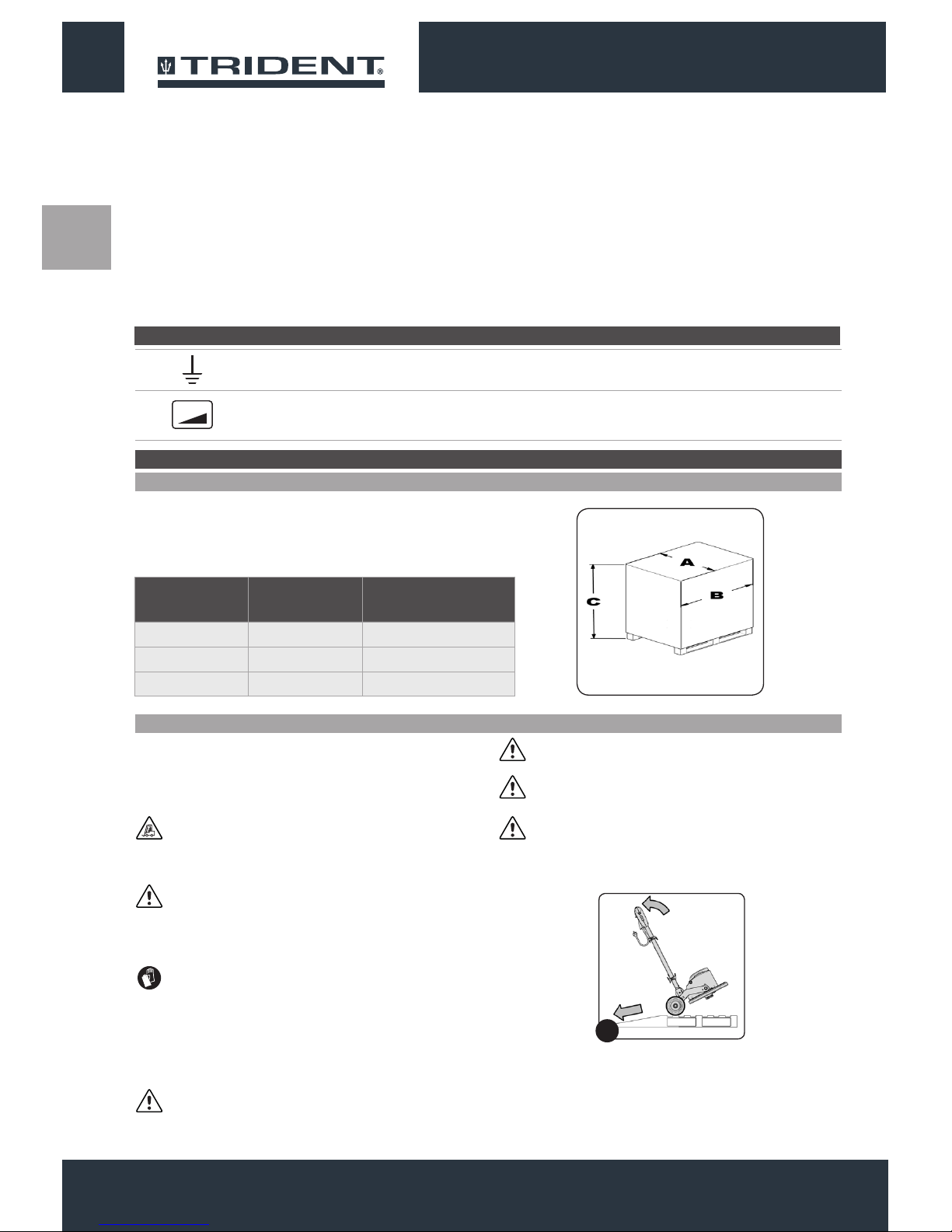
Warning symbol that the carriage is moving:
Indicates that the packed product should be handled with suitable lifting means that comply with the legal requirements.
Open book symbol with an “i”:
Indicates the need to consult the instruction manual.
The descriptions contained in this document are not binding. The company therefore reserves the right to make any modications at any time
to elements, details, or accessory supply, as considered necessary for reasons of improvement or manufacturing/commercial requirements.
The reproduction, even partial, of the text and drawings contained in this document is prohibited by law.
The company reserves the right to make any technical and/or supply modications. The images are shown as a reference only, and
are not binding as to the actual design and/or equipment.
Open book symbol:
Tells the operator to read the manual before using the appliance.
Protective gloves symbol:
Always wear protective gloves, to avoid the risk of serious injury to your hands.
SYMBOLS USED IN THE MANUAL
PURPOSE AND CONTENT OF THE MANUAL
TARGET GROUP
STORING THE USE AND MAINTENANCE MANUAL
ON DELIVERY OF THE APPLIANCE
INTRODUCTORY COMMENT
The aim of this manual is to provide customers with all the information
needed to use the appliance in the safest, most appropriate and
most autonomous way. It includes information concerning technical
aspects, safety, operation, appliance downtime, maintenance, spare
parts and scrapping. Operators and qualied technicians must read
This manual is aimed at operators and qualied technicians
responsible for appliance maintenance. Operators must not perform
operations that should be carried out by qualied technicians. Cannot
The Use and Maintenance Manual must be stored in its special
pouch close to the appliance, protected from liquids and anything
When the machine is delivered to the customer, an immediate
check must be performed to ensure all the material mentioned in
the shipping documents has been received, in addition to verifying
that the equipment has not been damaged during transportation. If
Any type of equipment can only work properly and effectively if used
correctly and kept in full working order by performing the maintenance
operations described in the attached documentation. You should
therefore read this instruction manual carefully, consulting it again
if difculties should arise while using the machine. If necessary,
the instructions in this manual carefully before carrying out any
operation on the appliance. If in doubt about the correct interpretation
of instructions, contact your nearest Customer Service Centre to
obtain the necessary clarications.
be held liable for damages resulting from failure to comply with this
prohibition.
else that could compromise its legibility.
this is the case, the carrier must ascertain the extent of the damage
at once, informing our customer service ofce. It is only by prompt
action of this type that the missing material can be obtained, and
compensation for damage successfully claimed.
remember that our assistance service (organised in collaboration
with our dealers) is always available for advice or direct intervention.
55 5

EN
IDENTIFICATION DATA
For technical assistance or to request replacement parts, always give the model, the version and serial number written on the serial number
plate.
TECHNICAL DESCRIPTION
INTENDED USE
SAFETY
SERIAL NUMBER PLATE
This appliance has been built for the professional cleaning of indoor hard vinyl oors, to be carried out by following the instructions. The
appliance must only be used for this purpose.
This appliance was designed and built to be used by a qualied
operator to clean smooth, compact ooring in the commercial,
residential and industrial sectors, in proven safety conditions. The
machine is suitable for carpet oor cleaning if used with proper
accessories. The appliance is only suitable for use in indoor - or at
least covered - areas.
Operator cooperation is paramount for accident prevention. No
accident prevention programme can be effective without the full
co-operation of the operator who is directly responsible for machine
operation. The majority of occupational accidents that happen both
in the workplace or whilst moving are caused by failure to respect
The serial number plate is located at the rear of the handlebar, and
indicates the general characteristics of the appliance, in particular
the appliance's serial number. The serial number is a very important
piece of information and should always be provided together with any
request for assistance or when purchasing spare parts.
ATTENTION: The appliance is not suitable for use in the rain,
or under jets of water.
the most basic safety rules. An attentive, careful operator is most
effective guarantee against accidents and is fundamental in order to
implement any prevention programme.
66
6
TECHNICAL DATA U/M TRIDENT FMD20
ORBITAL
Working width in 20
Pad holder diameter in 20
Engine speed Rot./min. 1400
Number of orbits dragging disc Orb./min. 1400
Brush head motor rated power W 1100
Brush head motor nominal voltage V 120
Brush head motor frequency Hz 50 / 60
Maximum gradient with full load % 2
Solution tank capacity (optional) gal 3,96
Rear wheels (diameter / width) in 7.9 - 1.8
Appliance length in 30,1
height of the appliance to the brush head carter in 12,6
Height of the appliance to the shaft in 48
Appliance width in 21,25
Appliance service weight (without solution tank) Lb 154,3
Length of power supply cable yd 16,4

EN
The regulations below must be carefully followed in order to avoid
harm to the operator and damage to the appliance.
WARNING:
• This appliance should not be used by people (including children)
with reduced physical, sensorial and mental capabilities, or by
people without any experience or knowledge, unless they have
been controlled and instructed in the use of the appliance by
people responsible for their safety. Children must be supervised
to ensure they do not play with the appliance.
• Carefully read the labels on the appliance. Do not cover them
for any reason and replace them immediately if they become
damaged.
• The appliance must always be stored and used in a closed
place.
• The appliance must be only used by authorised, trained
personnel.
• Do not use the appliance on surfaces with an inclination greater
than the one shown on the serial number plate.
• Always make sure that the work surfaces, oors and ramps, are
able to withstand the weight of the appliance.
• The appliance is not suitable for cleaning rough or uneven
oors. Do not use the appliance on slopes.
• In the event of danger, quickly remove the power cable plug
from the mains socket.
• For all maintenance interventions, switch off the machine and
disconnect the power cable from the socket.
• To prevent unauthorised use of the machine, the power supply
should be interrupted, switch off the appliance and pull out the
power cable from the socket.
• Children must be supervised to ensure they do not play with the
device.
GENERAL SAFETY REGULATIONS
77 7

EN
• When using the appliance, pay attention to other people and especially
to children.
• The appliance must only be powered with a voltage and a frequency
equal to that shown on the serial number plate.
• When left unattended, the appliance must be protected from
unintentional movements.
• Do not approach the machine with clothes that can get entangled,
AVOID the use of scarves, shawls, wraps and loose clothing.
• Avoid working over pieces of rope, wire, cables: these can be caught
in the brush and create friction.
WARNING:
• The appliance must not be used or kept outdoors, in damp conditions
or directly exposed to rain.
• The appliance must be stored in a closed area with a temperature
between -13°F and +131°F.
• Conditions of use: room temperature between 32°F and 104°F, with
relative humidity between 30 and 95%.
• The machine is suitable for carpet oor cleaning if used with proper
accessories.
• Polishing operations should only be carried out in areas where the
passage of unauthorised persons is prohibited. Signal the presence
of work areas with suitable signs.
• The socket for the machine power cable must have a prescribed earth
connection.
• Avoid damaging the machine power cable by crushing or bending it,
or by applying stress.
• Attention: do not let the power cable come into contact with the
rotating brush.
• The appliance does not cause harmful vibrations.
• If the appliance is used in dangerous areas (for example, gas
stations), the relative safety norms should be observed. The appliance
must never be used in environments with a potentially explosive
88
8

EN
atmosphere.
• In the event of a re, use a powder extinguisher. Do not use water.
• Avoid using the brushes while the appliance is at a standstill, so as
not to damage the oor.
• Do not knock against shelving or scaffolding, where there is a danger
of falling objects. The operator must always be equipped with the
appropriate safety devices (gloves, shoes, helmet, goggles, etc.).
• If the appliance does not work properly, check this is not caused
by failure to carry out routine maintenance. Otherwise, ask for
intervention of the authorised technical assistance centre.
• If you need to replace any components, request the ORIGINAL spare
parts from an Authorised dealer and/or Retailer.
• Restore all electrical connections after any maintenance interventions.
• Have the appliance checked by an authorised technical assistance
centre every year.
• When disposing of consumable materials, observe the laws and
regulations in force. When, after years of valuable work, your
appliance needs to be nally decommissioned, dispose of the
materials contained in it appropriately, bearing in mind that the
appliance is made of fully recyclable materials.
• If the power supply cable gets damaged, the appliance must be
stopped if it is operating. Disconnect the plug from the power supply,
and have the cable replaced immediately by an authorised service
centre.
• Before using the appliance, check that all the hatches and covers are
positioned as shown in this Use and Maintenance Manual.
• Only use the discs supplied with the device, or those specied in the
Instruction Manual. The use of other discs could compromise safety
levels.
• Before connecting the appliance to the power outlet, check that
the electrical data on the nameplate corresponds to those of the
power supply. The appliance must only be powered by alternating
99 9

EN
current and with a voltage equal to that indicated on the
serial number plate.
Appliance's earth symbol:
Indicates the earth connection point of the appliance's electric system.
Maximum gradient symbol:
Indicates the maximum gradient.
SYMBOLS USED ON THE APPLIANCE
GETTING TO KNOW THE APPLIANCE
HANDLING THE PACKED APPLIANCE
HOW TO UNPACK THE APPLIANCE
Since the packaging elements (plastic bags, staples, etc.) are a
potential source of danger, they should not be left within the reach of
children, disabled persons, etc.
The overall weight of the appliance with packaging is 169,7 lb (weight
of empty machine plus packaging).
The dimensions of the package are as follows:
The appliance is contained in specic packaging; to remove the
appliance from the packaging proceed as follows:
1. Place the lower part of the outer packaging in contact with the
oor.
ATTENTION: Indicates that the packed product should be
handled with suitable lifting devices that comply with the legal
requirements
ATTENTION: Use the pictograms printed on the box as
reference.
2. Remove the holding straps.
3. Open the outer packaging.
ATTENTION: You are advised to always wear protective
gloves, to avoid the risk of serious injury to your hands.
4. Remove the optional accessories contained in the packing.
5. Pull the outside box upwards.
6. Remove the machine's holding straps.
7. Using a chute, bring the device down from the pallet, pushing it
backwards.
ATTENTION: During this operation, check there are no
people or objects near the machine.
ATTENTION: Do not mount the pad holder before unloading
the machine, in order to avoid brush head being violently hit.
ATTENTION: To remove the appliance from the box do not
use the control handlebar since it could be damaged.
ATTENTION: it is recommended that all the packaging
components be kept for any future transportation of the
appliance.
1010
10
X%
1
U/M TRIDENT FMD20
ORBITAL
Ain 24.7
Bin 53.9
Cin 32.3

EN
HOW TO TRANSPORT THE APPLIANCE
To safely transport the appliance, proceed as follows:
1. Take all necessary steps to ensure that the device is in a safe
condition (see “MACHINE SAFETY”).
2. Using a chute, bring the appliance up onto the pallet, pushing
it backwards.
3. Lay the brush head on top of the pallet.
4. Using the straps, x the appliance to the pallet.
5. Now the appliance can be transported safely.
ATTENTION: You are advised to always wear protective
gloves, to avoid the risk of serious injury to your hands.
ATTENTION:When transporting the appliance on vehicles,
secure it according to the directives in force so that it cannot
slide or tip over.
MAIN COMPONENTS OF THE APPLIANCE
MAIN COMPONENTS OF THE CONTROL HANDLEBAR
The basic components of the appliance are as follows:
1. Control handlebar.
2. Frame.
3. Brush head.
The handlebar components are identied as follows:
1. dead man's lever.
2. Control lever main switch (positioned under the grip of the
handlebar).
3. Handlebar tilt adjustment lever.
4. Detergent distribution valve control lever.
5. Brush head motor thermal circuit breaker.
6. Power cable.
7. Socket for electric tool.
4. Brush head carter.
5. Pad holder.
6. Power cable 16,4Yd.
7. Solution tank kit.
1111 11
1
6
3-4
7
25
4
1
6
3 7
2 5
1
1 2
1

EN
MAIN COMPONENTS OF THE COLUMN
The handlebar components are identied as follows:
1. Upper support optional solution tank kit.
To insert the pad holder into the brush head body of the appliance,
proceed as follows:
1. Check that the plug (1) on the power cable (2) has been taken out
of the socket (3) of the mains supply(Fig.1), and if not, disconnect
it.
ATTENTION: You are advised to always wear protective
gloves, to avoid the risk of serious injury to your hands.
2. Lower support optional solution tank kit.
3. Upper cable tidy.
4. Lower cable tidy.
ATTENTION: To prevent damaging the power cable,
disconnect the plug from the mains socket by directly pulling
the plug and not the cable.
2. Check that the handlebar is in the vertical position, if not, press
the uncoupling lever (4) (Fig.2) and turn the handlebar to the
vertical position (Fig.3). When the handlebar is vertical, release
the uncoupling lever (4).
PREPARATION OF THE APPLIANCE
INSERTING THE PAD HOLDER
3. Lightly tip the machine back (Fig.4), block one of the rear wheels
and shift the control column backwards.
4. Turn the brush head into the vertical position (Fig.5).
5. Bring the rotated brush head into contact with the oor (Fig.6).
1212
12
4
3
2
1
2
1
3 4
1
1 2 3
2
456

EN
6. Unscrew and remove the tightening keys (5) (Fig.7).
7. Insert the pad holder, being careful to centre the xing pins (6) in
the appliance with the holes (7) in the pad holder (Fig.8).
8. Screw in the tightening keys (5) (Fig.9)
ATTENTION: To tighten the keys correctly use a tightening
clamp.
If the pad holder is used for emery paper, proceed as follows:
• Unscrew and remove the tightening keys (5) (Fig.7).
• Insert the pad holder, being careful to centre the xing pins (6) in
the appliance with the holes (7) in the pad holder (Fig.8).
• Insert the centring ange (8) (Fig.10).
• Insert the threaded grab (9), making sure to centre the xing pins
in the appliance with the holes in the threaded grab (Fig.11).
Screw in the tightening keys (5).
ATTENTION: To tighten the keys correctly use a tightening
clamp.
• Insert the emery paper disc above the pad holder.
• Fix the emery paper to the pad holder using the nut (10)
remembering to also insert the washer (11) (Fig.12).
ATTENTION: To correctly tighten the nut, use a suitable tool.
9. Lightly tip the machine back (Fig.13), block one of the rear
wheels and shift the control column backwards.
10. Turn the brush head into the work position (Fig.13).
1313 13
5
8
811
510
7 5
6
7
11 1210
8 9
1413

EN
To insert the solution tank onto the handlebars, proceed as follows:
1. Secure the handlebar in a position at about 45° with respect to
the ground (Fig.1).
Fill the solution tank only when the column is in vertical position, by
proceeding as follows:
1. Remove the solution tank cap (1) (Fig.1).
2. Fill with clean water, at a temperature no higher than 50°C.
3. Add the liquid detergent to the tank in the concentration and
manner indicated on the detergent manufacturer's label. The
formation of excess foam could damage the internal components
of the machine, so only use the minimum amount of detergent
needed.
2. Unscrewing the closing knob (1) (Fig.2) position the upper
brackets beyond half of the column (Fig.3) (if it has not already
been positioned).
4. Insert the solution tank cap (1) (Fig.2).
ATTENTION: You are advised to always wear protective
gloves, to avoid the risk of serious injury to your hands.
ATTENTION: We recommend that you vacuum at intervals
the dirt-loaded foam with a vacuum cleaner for liquids.
INSERTING THE SOLUTION TANK (OPTIONAL)
INSERTING THE DETERGENT SOLUTION (OPTIONAL)
3. Put the solution tank on the column, so that the bottom of the tank
is anchored to the xed bracket (2) on the column itself (Fig.4).
4. Holding the tank with one hand, move the mobile bracket (3)
down until the solution tank is locked to the column (Fig.5).
5. Lock the position of the mobile bracket (3) by tightening the
closing knob (1) (Fig.6).
6. Insert the water distribution pipe (4) in the hole on the brush head
(5) (Fig.7).
7. Insert the solution tank tap tie chain (6) in the coupling in the tap
control handle (7) (Fig.8).
1414
14
1
4
7
2
5
8
3
6
1
2
5 4
6
7
3 3
1

EN
Before beginning to work, it is necessary to:
1. Before using, the appliance must be in order and safe to use
with the work equipment, especially the power cable and the
extension cable. If everything is not in order, the appliance must
not be used.
2. Insert the plug (1) of the power supply cable (2) in the mains
supply socket (3) (Fig.1).
3. Release the control handlebar from the vertical position. Press
the control column stop lever (4) in the direction indicated by
the arrow (Fig.2) and turn the control column towards yourself
(Fig.3).
ATTENTION: During this operation, do not rest your foot on
the appliance.
WORK
4. Turn the control column towards you until you nd the best
position, this position should be comfortable when using the
appliance.
5. Once the ideal position has been found, release the control
column stop lever (4) to lock the handlebar.
6. Turn the dead man's handle towards you (5) (Fig.4).
7. Press the control levers main switch (6), located under the grips
on the handlebar (Fig.5).
8. The appliance will now start to move.
9. Apply a small amount of detergent solution to the oor by
pressing the lever (7) (Fig.6), until the brush is saturated with
foam (optional solution tank kit).
10. Push the machine with the brush rotating from left to right or vice
versa.
11. Immediately afterwards, push the machine in the same way but
in the opposite direction, so that about one quarter of the working
width overlaps the previous one.
12. We recommend that you vacuum up the dirt-loaded foam at
intervals with the aid of a vacuum cleaner for liquids (optional
solution tank kit).
ATTENTION: The rst time an operator uses the machine, he/
she should become familiar with the movements to be
imparted to the shaft in order to be condent enough with the
directionality of movement of the machine, and should
therefore not operate the machine near people or obstacles.
ATTENTION: Work in slow movements to the right and left,
possibly moving back so that the operator always stands on
an area of the oor yet to be cleaned up.
ATTENTION: Keep the power supply cable behind the
operator, taking care not to operate the machine in its vicinity
in order not to damage it.
ATTENTION: Do not insist too much on the same area so as
to avoid damaging the oor, also in function of the type of
brush or abrasive oor pad chosen.
ATTENTION: If you need to work in tight spaces you can turn
the control column to the vertical position.
1515 15
1 2
1 1
1
2
3
5
4
7
6
1
4
2
5
3
6

EN
At the end of the work, and before carrying out any type of
maintenance, perform the following operations:
1. Disconnect the plug (1) of the power supply cable (2) in the mains
supply socket (3) (Fig.1).
ATTENTION: You are advised to always wear protective
gloves, to avoid the risk of serious injury to your hands.
ATTENTION: To prevent damaging the power cable,
disconnect the plug from the mains socket by directly pulling
the plug and not the cable.
2. Turn the handlebar to the vertical position, press the uncoupling
lever (4) (Fig.2) and turn the handlebar to the vertical position
(Fig.3). When the handlebar is vertical, release the uncoupling
lever (4).
AT THE END OF WORK
ATTENTION: During this operation, do not rest your foot on
the appliance.
3. Tip back the machine and take the appliance to the place where it
is maintained and carry out all the procedures listed in the section
“RECOMMENDED PERIODIC MAINTENANCE” indicated in the
column “AT THE END OF THE WORK”.
4. Once the maintenance work is nished take the appliance to the
designated machine storage place.
ATTENTION: Park the machine in an enclosed place, on a at
surface; near the machine there must be no objects that could
either damage it, or be damaged through contact with it.
5. Lightly tip the machine back (Fig.4), block one of the rear wheels
and shift the control column backwards.
6. Turn the brush head into the vertical position (Fig.5).
7. Bring the rotated brush head into contact with the oor (Fig.6).
RECOMMENDED MAINTENANCE OPERATIONS
MAINTENANCE
1616
16
1
2
3 4
1 2 3
4 5 6
TYPE OF MAINTENANCE
AT THE END OF
WORK
WEEKLY
BEFORE A LONG
PERIOD WHEN
IT WILL NOT BE
USED
TRANSPORTING
Checking and cleaning the pad holder X X X
Checking and cleaning the solution tank (optional) X X X

EN
Careful cleaning of the pad holder guarantees better cleaning of the
oor as well as a longer brush motor life. To clean the pad holder,
proceed as follows:
1. Take the appliance to the dedicated dirty water drainage area.
ATTENTION: The place this operation is carried out should
comply with current environmental protection regulations.
2. Check that the plug (1) on the power cable (2) has been taken out
of the socket (3) of the mains supply(Fig.1), and if not, disconnect
it.
ATTENTION: You are advised to always wear protective
gloves, to avoid the risk of serious injury to your hands.
ATTENTION: To prevent damaging the power cable,
disconnect the plug from the mains socket by directly pulling
the plug and not the cable.
3. Check that the handlebar is in the vertical position, if not, press
the uncoupling lever (4) (Fig.2) and turn the handlebar to the
vertical position (Fig.3). When the handlebar is vertical, release
the uncoupling lever (4).
CHECKING AND CLEANING THE PAD HOLDER
4. Lightly tip the machine back (Fig.4), block one of the rear wheels
and shift the control column backwards.
5. Turn the brush head into the vertical position (Fig.5).
6. Bring the rotated brush head into contact with the oor (Fig.6).
7. Unscrew and remove the tightening keys (5) (Fig.7).
8. Remove the pad holder, remove the impurities in it.
9. Repeat the operations in reverse order to reassemble all the
parts.
ATTENTION: To tighten the keys correctly use a tightening
clamp.
1717 17
1
2
3 4
1 2 3
5
7
456

EN
Carefully cleaning the solution tank ensures the oor is cleaned
properly. Proceed as follows to clean the solution tank:
1. Take the appliance to the dedicated dirty water drainage area.
ATTENTION: The place this operation is carried out should
comply with current environmental protection regulations.
2. Check that the plug (1) on the power cable (2) has been taken out
of the socket (3) of the mains supply(Fig.1), and if not, disconnect
it.
ATTENTION: You are advised to always wear protective
gloves, to avoid the risk of serious injury to your hands.
ATTENTION: To prevent damaging the power cable,
disconnect the plug from the mains socket by directly pulling
the plug and not the cable.
3. Fix the handlebar in a position of about 45° to the ground, press
the uncoupling lever (4) (Fig.2) and turn the handlebar into
position (Fig.3). When the handlebar is in position, release the
uncoupling lever (4).
CHECKING AND CLEANING THE SOLUTION TANK (OPTIONAL)
4. Uncouple the solution tank tap tie chain (5) in the coupling in the
tap control handle (6) (Fig.4).
5. Remove the water distribution pipe (7) in the hole on the brush
head (8) (Fig.5).
6. Loosen the closing knob (9) (Fig.6) and position the top brackets
more than halfway up the column.
7. Remove the solution tank from the control column.
8. Remove the solution tank cap (10) (Fig.7).
9. Rinse the inside with a jet of water, if necessary use a spatula
to remove the sludge that has accumulated at the bottom of the
tank.
10. Repeat the operations in reverse order to reassemble all the
parts.
TROUBLESHOOTING
This chapter lists the most common problems linked with the use of the appliance. If you are unable to resolve the problems with
the information given here, please contact your nearest assistance centre.
DISPOSAL
To dispose of the appliance, take it to a demolition centre or an authorised
collection centre.
Before scrapping the appliance, it is necessary to remove and separate out
the following materials, then send them to the appropriate collection centres in
accordance with applicable environmental hygiene regulations:
• Pad holders or brushes
• Electric and electronic parts*
• Plastic parts
• Metallic parts
(*) In particular, contact your distributor when scrapping electric and electronic
parts.
1818
18
1
2
3 4
1 2 3
456
10
7
58
6
7
9

EN
TROUBLESHOOTING
1919 19
PROBLEM POSSIBLE CAUSE SOLUTION
THE APPLIANCE DOES NOT SWITCH ON
The power cable extension is not connected
to the mains socket.
Check that the plug on the extension cable
has been inserted into the mains supply
socket.
The power cable extension is not connected
to the appliance's power cable.
Check that the plug on the cable of the
appliance has been inserted into the socket
on the extension cable.
The electrical specications of the appliance
should correspond to the electrical
specications of the power supply network.
Make sure that the electrical specications
of the appliance correspond to the electrical
specications of the power supply network,
check the technical information on the serial
number plate.
Extension cable damaged. Check the extension cable is not damaged,
and if it is, replace it.
Overheating of the brush head motor.
Make sure that the thermal breaker on the
back of the handlebar has not tripped. If it
has, wait a few minutes until it has cooled
down, then press the specic circuit breaker
button to reactivate the power supply and
motor operation
INSUFFICIENT DETERGENT SOLUTION
ON THE PAD HOLDER
The amount of detergent in the solution tank
is insufcient for the work that needs doing.
Make sure that the amount of detergent
solution in the solution tank is sufcient for
the work to be carried out, and if necessary
ll the solution tank.
POS. COMPONENT
1 CONTACT BREAKER 16A
2 SWITCH 20A
3 START RELAY
4 START CONDENSER
5 WORK CONDENSER
6 MOTOR 1100W 100/115V 50/60HZ
8 PLUG
BK BLACK
BU BLUE
BN BROWN
RD RED
WH WHITE
GNYE YELLOW/GREEN
ELECTRICAL DIAGRAM

ES
ÍNDICE
ESPAÑOL
ÍNDICE ............................................................................................................................20
SIMBOLOGÍA UTILIZADA EN EL MANUAL..................................................................21
OBJETIVO Y CONTENIDO DEL MANUAL....................................................................21
DESTINATARIOS............................................................................................................21
CONSERVACIÓN DEL MANUAL DE USO Y MANTENIMIENTO .................................21
RECEPCIÓN DE LA MÁQUINA .....................................................................................21
ADVERTENCIA PREVIA.................................................................................................21
DATOS DE IDENTIFICACIÓN ........................................................................................22
DESCRIPCIÓN TÉCNICA...............................................................................................22
USO INDICADO - USO PREVISTO................................................................................22
SEGURIDAD...................................................................................................................22
PLACA DE LA MATRÍCULA...........................................................................................22
DATOS TÉCNICOS.........................................................................................................22
NORMAS GENERALES DE SEGURIDAD.....................................................................23
SIMBOLOGÍA UTILIZADA EN LA MÁQUINA................................................................26
CONOCIMIENTO DE LA MÁQUINA...............................................................................26
DESPLAZAMIENTO DE LA MÁQUINA EMBALADA.................................................26
DESEMBALAJE DE LA MÁQUINA............................................................................26
TRANSPORTE DE LA MÁQUINA..............................................................................27
COMPONENTES PRINCIPALES DE LA MÁQUINA .................................................27
COMPONENTES PRINCIPALES DEL MANILLAR DE MANDO...............................27
COMPONENTES PRINCIPALES DE LA COLUMNA................................................28
PREPARACIÓN DE LA MÁQUINA.................................................................................28
MONTAJE DEL DISCO DE ARRASTRE ...................................................................28
MONTAJE DEL TANQUE DE SOLUCIÓN (OPCIONAL)...........................................30
LLENADO DE SOLUCIÓN DETERGENTE (OPCIONAL).........................................31
USO.................................................................................................................................31
AL FINALIZAR EL TRABAJO........................................................................................32
MANTENIMIENTO ..........................................................................................................32
INTERVENCIONES DE MANTENIMIENTO ACONSEJADO ....................................33
CONTROL Y LIMPIEZA DEL DISCO DE ARRASTRE ..............................................33
CONTROL Y LIMPIEZA DEL TANQUE DE SOLUCIÓN (OPCIONAL) .....................34
DESGUACE ....................................................................................................................34
RESOLUCIÓN DE AVERÍAS..........................................................................................35
2020
20
Table of contents
Languages:
Popular Floor Machine manuals by other brands

Clarke
Clarke Fusion 20 troubleshooting guide

BETCO
BETCO FiberPRO 8 BFP8 operating instructions

Nobles
Nobles 24 brochure

Tennant
Tennant ATLV 4300 Instruction bulletin

Nilfisk-Advance
Nilfisk-Advance Sprite Plus 12 Instructions for use

Origin Cleaning Equipment
Origin Cleaning Equipment Vitesse UHS1553 operating guide