Tridium Expose DCT128 User manual

PARTNER INFORMATION
TRIDIUM
The Exposé Touchscreen User Guide
DOCUMENT RELEASE
DOC REFERENCE: teu-jb-141_3.doc
DATE 31st May ‘12
3
PAGE 1 of 18
The Exposé Touchscreen User Guide
Copyright © TRIDIUM. INC.
TRIDIUM EUROPE

Contents
PARTNER INFORMATION
TRIDIUM
The Exposé Touchscreen User Guide
DOCUMENT RELEASE
DOC REFERENCE: teu-jb-141_3.doc
DATE 31st May ‘12
3
PAGE 2 of 18
Contents:
Contents:................................................................................................................2
Preface....................................................................................................................3
Exposé ID3000 FAQs....................................................................................4
Compatibility and Installation...............................................................................5
Compatibility..................................................................................................5
License requirements....................................................................................5
Software installation......................................................................................5
Unpacking the touchscreen...........................................................................6
Mounting the Touchscreen............................................................................7
Limitations and known problems...................................................................11
Quick Start..............................................................................................................12
Setup the touchscreen ..................................................................................12
Connect to target...........................................................................................17
Related documents................................................................................................18
Document Control .................................................................................................18
This is an 18 page document at A4

Preface
PARTNER INFORMATION
TRIDIUM
The Exposé Touchscreen User Guide
DOCUMENT RELEASE
DOC REFERENCE: teu-jb-141_3.doc
DATE 31st May ‘12
3
PAGE 3 of 18
Preface
This is the User Guide for the DCT128 Exposé 8” colour touchscreen which has an 800 x 600 resolution
and provides a cost-effective solution wherever a wall or panel mounted user interface is required. Exposé
is based on a fanless Atom powered PC platform which has been specially configured by Tridium to enable
easy set-up. The DCT128 uses a custom Linux OS running Firefox in kiosk mode; optimised for use with
Niagara AX web-served graphical pages.
The DCT128 is equipped with a wired IP connection, and requires a 12Vdc supply (230V to 12V PSU is
included). Exposé also includes Wi-Fi connectability, a camera and a speaker (these are currently not
supported by NiagaraAX).
The front panel of Exposé is completely flat which makes it more visually attractive and easier to clean. It is
IP64 compliant when used with the optional panel-mounting kit. The DCT120 can also be surface mounted
on a wall, or flush-mounted using optional kits. These mounting options make Exposé suitable for a wide
variety of uses in commercial and residential applications. The following main sections are in this
document:
“Compatibility and Installation”
Explains the touchscreen and JACE network architecture, software, licensing requirements, unpacking
and mounting the touchscreen, limitations and known problems.
“Quick Start”
Provides the procedure for setting up the touchscreen for Network, Target Station, Password, Time,
Locale and Browser.

Preface
PARTNER INFORMATION
TRIDIUM
The Exposé Touchscreen User Guide
DOCUMENT RELEASE
DOC REFERENCE: teu-jb-141_3.doc
DATE 31st May ‘12
3
PAGE 4 of 18
Exposé ID3000 FAQs
The following are frequently asked questions (FAQs) about the Exposé:
Q: As well as the touchscreen and its power leads, the carton also contains some CD’s and a multi core
cable with a USB plug and other connectors. What do I do with these?
A: You do not need them. They are not used in this Tridium implementation. In addition, the Exposé
touchscreen has a built-in camera, a microphone, some speakers, two USB ports, an RS-232 port, an
RS-232/422/485 port, an audio output and wireless networking capabilities for Bluetooth 2.0 and
802.11 b/g. These are also not used nor supported in this Tridium implementation.
Q: I want to use the browser of the touchscreen to access the internet. How can I do this?
A: You should not try to do this. In this Tridium implementation, the browser in the Exposé touchscreen is
designed to automatically connect to a preconfigured JACE station. The browser is not enabled to do
anything else.
Q: Do I need a NiagaraAX license to use the Exposé touchscreen?
A: No. The Exposé touchscreen connects to a JACE station with a browser and no extra licenses are
required.
Q: Will the touchscreen support both Px and Hx media?
A: Yes. Both formats of NiagaraAX graphics media are supported.
Q: I notice that there are two Ethernet connectors on the touchscreen. Can I use either of them?
A: Yes, either one of the Ethernet connections can be used. However, the touchscreen does not support
the use of them both simultaneously.

Compatibility and
Installation
PARTNER INFORMATION
TRIDIUM
The Exposé Touchscreen User Guide
DOCUMENT RELEASE
DOC REFERENCE: teu-jb-141_3.doc
DATE 31st May ‘12
3
PAGE 5 of 18
Compatibility and Installation
This section has the following main subsections:
Compatibility
License requirements
Software installation
Unpacking the touchscreen
Mounting the touchscreen
Limitations and known problems
Compatibility
The touchscreen has the following compatibility criteria:
NiagaraAX station compatibility
NiagaraAX network compatibility
NiagaraAX station compatibility
The touchscreen will function with all NiagaraAX stations that have web served graphics pages.
NiagaraAX network compatibility
The touchscreen has been designed to function as a browser which communicates with a target NiagaraAX
station, typically running in a JACE controller. This is illustrated in Figure 1-1
License requirements
There are no license requirements needed to setup or operate the touchscreen
Software installation
The Exposé touchscreen is already installed with a Compact Flash memory card which allows it to operate
in this Tridium implementation.
Ethernet IP Network
The touchscreen auto starts with its browser
preset to browse a Target station
Figure 1-1The touchscreen architecture
JACE controller network
Target
station

Compatibility and
Installation
PARTNER INFORMATION
TRIDIUM
The Exposé Touchscreen User Guide
DOCUMENT RELEASE
DOC REFERENCE: teu-jb-141_3.doc
DATE 31st May ‘12
3
PAGE 6 of 18
Unpacking the touchscreen
To unpack the touchscreen, follow these steps:
Note: The Exposé touchscreen has a protective plastic cover stuck to the screen. Only remove the
plastic cover after the touchscreen has been properly installed. This ensures the screen is
protected during the installation process.
To Unpack the touchscreen
Step 1 Use box cutters, a knife or a sharp pair of scissors to cut the seal on the top side of the external
box.
Step 2 Open the external box.
Step 3 Use box cutters, a knife or a sharp pair of scissors to cut the seal on the top side of the inner box.
Step 4 Open the inner box.
Step 5 Lift the touchscreen out of the inner box.
Step 6 Remove both polystyrene ends, one from each side.
Note: The Exposé touchscreen is already installed with a Compact Flash memory card which allows it to
operate in this Tridium implementation. There are no user configurable settings inside the
touchscreen and therefore there is no need to remove the cover retaining screws.
Compatibility and
Installation
PARTNER INFORMATION
TRIDIUM
The Exposé Touchscreen User Guide
DOCUMENT RELEASE
DOC REFERENCE: teu-jb-141_3.doc
DATE 31st May ‘12
3
PAGE 7 of 18
Mounting the Touchscreen
There are several methods of mounting the Exposé Touchscreen. These are listed in the following
subsections:
Panel mounting (Kit reference: DPM128)
Wall (surface) mounting (Kit reference: DWM128)
Wall (flush in-wall cage) mounting (Kit reference: DFM128)
Note: When mounting the touchscreen onto an arm, wall or panel, it is advisable to have more than one
person to help with the installation to make sure that the touchscreen does not fall and get
damaged.
Panel Mounting (DPM128)
To mount the touchscreen on a panel, follow these steps:
To Panel mount the touchscreen
Step 1 Select the position on the panel for the touchscreen.
Step 2 Cut a section from the panel that corresponds to the rear dimensions of the touchscreen. Take
care that the panel section that is cut out is smaller than the overall size of the frame but larger than
the rear part of the touchscreen body.
Step 3 Slide the touchscreen through the hole until the frame is flush against the panel.
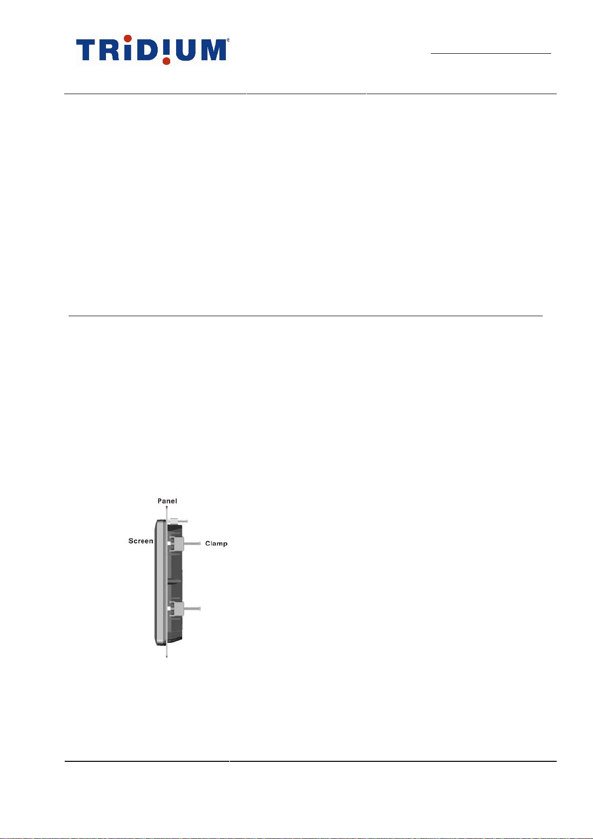
Step 4 Insert the panel mounting clamps into the pre-formed holes along edges of the chassis, behind the
frame.
Step 5 Tighten the screws that pass through the panel mounting clamps until the plastic caps, at the front
of all the screws are firmly secured to the panel. Figure 1-2
Figure 1-2: Tighten the panel mounting clamp screws
Compatibility and
Installation
PARTNER INFORMATION
TRIDIUM
The Exposé Touchscreen User Guide
DOCUMENT RELEASE
DOC REFERENCE: teu-jb-141_3.doc
DATE 31st May ‘12
3
PAGE 8 of 18
Wall (surface) Mounting (DWM128)
To surface mount the touchscreen on a wall, follow these steps:
To Wall (surface) mount the touchscreen
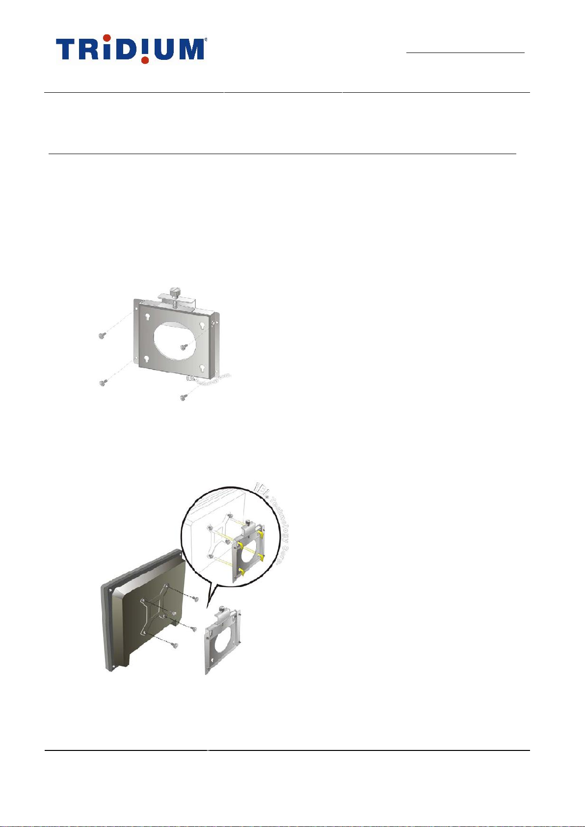
Step 1 Select the location on the wall for the wall-mounting bracket.
Step 2 Carefully mark the locations of the four screw holes in the bracket on the wall
Step 3 Drill four pilot holes at the marked locations on the wall for the bracket retention screws
Step 4 Align the wall-mounting bracket screw holes with the pilot holes
Step 5 Secure the mounting-bracket to the wall by inserting the retention screws into the four pilot holes
and tightening them. Figure 1-3
Step 6 Insert the four monitor mounting screws provided in the wall-mounting kit into the four screw holes
on the rear touchscreen and tighten until the screw shank is secured against the rear touchscreen.
Figure 1-4
Note: Please use the M4 screws provided in the wall mounting kit for the rear touchscreen. If you need to
replace any missing screws ensure that the thread depth is no greater than 4mm.
Step 7 Align the mounting screws on the touchscreen rear panel with the mounting holes on the bracket.
Figure 1-3: Wall-mounting Bracket
Figure 1-4: Chassis support screws

Compatibility and
Installation
PARTNER INFORMATION
TRIDIUM
The Exposé Touchscreen User Guide
DOCUMENT RELEASE
DOC REFERENCE: teu-jb-141_3.doc
DATE 31st May ‘12
3
PAGE 9 of 18
Step 8 Carefully insert the screws through the holes and gently pull the touchscreen downwards until the
touchscreen rests securely in the slotted holes (Figure 1-4). Ensure that all four of the mounting
screws fit snugly into their respective slotted holes.
Step 9 Secure the touchscreen by fastening the retention screw of the wall-mounting bracket (Figure 1-5)
Wall (flush in-wall cage) Mounting (DFM128)
To flush mount the touchscreen on a wall, follow these steps:
To Wall (flush in-wall cage) mount the touchscreen
Step 1 Select the position on the wall for the touchscreen.
Step 2 Cut a section from the wall that corresponds to the rear dimensions of the wall-cage frame. Take
care that the wall section that is cut out is smaller than the overall size of the frame but larger than
the rear part of the wall-cage body. The wall-cage frame is illustrated in Figure 1-6
Figure 1-5: Secure the Touchscreen
Figure 1-6: The wall-cage frame
Wall fixing holes
Compatibility and
Installation
PARTNER INFORMATION
TRIDIUM
The Exposé Touchscreen User Guide
DOCUMENT RELEASE
DOC REFERENCE: teu-jb-141_3.doc
DATE 31st May ‘12
3
PAGE 10 of 18
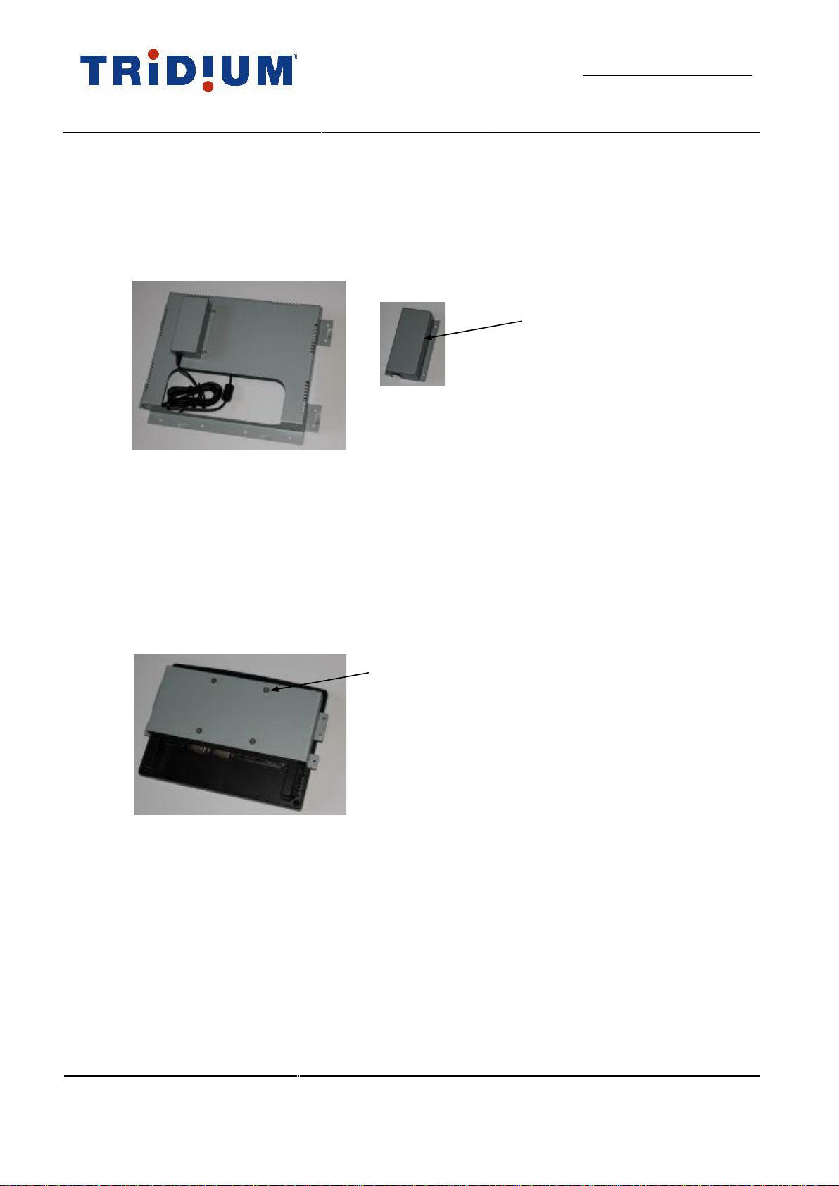
Step 3 Position the power adapter unit into its retaining bracket and attach the completed assembly to the
rear of the wall-cage frame using the screws provided in the kit. Figure 1-7
Note: Depending on the amount of free access behind the wall for cables, you may wish to invert the
power adapter retaining bracket assembly to allow the mains power lead connector more space for
final assembly.
Step 4 Secure the wall-cage frame to the wall using the holes around the periphery of the frame. (Screw
fixings are not provided)
Step 5 Attach the touchscreen bracket using the four mounting screws provided in the kit into the four
screw holes on the rear touchscreen and tighten. Figure 1-8
Note: Please use the M4 screws provided in the wall mounting kit for the rear touchscreen. If you need to
replace any missing screws ensure that the thread depth is no greater than 4mm.
Step 6 Make the necessary electrical and communications connections to the touchscreen.
Figure 1-8: Touchscreen bracket
4 mounting screws
Figure 1-7: Attach the power adapter
Power adapter retaining bracket
Table of contents


