Sommerkamp SRG-8600DX User manual
Riflomfmcofi
E
ozqosdmzoEES
Ema
.
:0
#222533.
220505.;
no
«assaufifizdz
E§
fig
a<DZ<<<
02:.(zun—O
_
XaOOomumvmm
to
OZ<ODJ\MZO_&_2<U
:mm
o
I0
5.1.553
229.53.
.0 2555555.:
gama-wma¢a
._<DZ<<<
02_h<~_un_0
XnOOowAvu—m
.5-
_
omxumcofi
E
02<03fi205240
53 .
ro
hzus_a_:cw
u.:0=>uu..u
10
u:n=:bu<nn.ää
4<DZ<<<
Oz_h<mmn_o
XDOOON-01m
„O-:„mxumxfizi
_„‚_
|‘31100485[8501-01
SRG-8600D
OPERATING
MANUAL
nnnnnnnnnnnnnnnnnnnnnnnnnnnn
CH ° 8911 CAMF’IONE/LUGANO
$RG-8600DX
OPERATING
MANUAL
uuuuuuuuuuuuuuuuuuuuuuuuuuu
CH ° 8911 CAMPIONE/LUGANO
.lmll
:0N
<
$0000
0::
:0
:000Elm
0E00:m
5—00-03:
0 3
00:00:05
0:
::w:0.sm.
:0:w_w
000320
0:00
0:0:
0:0
:0
0000005
00000
00:5
mm
..
._..
...
.....
.r
...
..
..
.. .
..
.7.
..
..
ZOEKSEOEZH
05M0<m
\m2m2
0::
:00:
03000200
00
00000
w:E:00m
.m_0::0:0
..\m._:0-:0_t00:
0m
3.1.1.111...
AER—am
H60
0::
AONFZO0
MMHDE200
E02m—m
030005
:0
9:000?
0_0>0
00
030000200
020
2
wEwc0m
00:0
. .
:000
2000
.0000
:00:
w:_m:0m
00:00
00
:03000
E
0:500:1050
:00:
@5500:
_0::0:0
59:08
00
:03
m0
wE::000
0:0:
A00EE0:m0.a
mm
..
._
..
..
..
a
..
..
._
.
..
w:_:00_:02
_0::0:0
3:005
000x00:
003E:
:0
:3
$50
030:0
E00003
wr:::00m
0::
mm
.
..
....
q
.
...
..... ...
0030.000
000m
00fiE5
mm...
a
1....
a
u
tII
a.
u
0....
o
._
a
.-
.a
-
COfi—whao
h®E~H\v—8~U
.888
=0
E
magma
0%
mafia
200:0
20
R
.
..
500030
8008035500
Emmy
28800050
00:0
2:80
#052
20
E8:
5058
8:8
wszsmoflwafia
550
mm
.
..
...
._
2-533-043
0:00:82
8008:3558
0:802
.32
0:09:80:
0:0
:50
.m—mm
:0
wESfi
$2950
00
00006.5
3
00::
0N
..
..
..
..
...
...
AZI2n:
w::0::02
0:0300ESEE00
03:03,:
m:_:3
0:00
0:0:
0
0:0
.A:00:m0:0:0_00:
30 00
:030000:
0800
:0.“
00030::
000
0008
mwm
05L
.EI>
:0.“
0:33
0::
00
0008
0:0
00
.-
Nu
.. ..... .
w:_::00m
59:02
0:0
:000m
0W0:00m
50:02
b_0u:0_.::00x0
0:0
00002::
0::
3
00m:
30:
0008
mm0<
B0:
0::
00
on
. .
..
...
...
._
..
..
..
.
H.
..
.
2542
r:
E.0_.E000~_
00000005
SE
:03
m0
.mmm
@0022:
0:0
300050
:0
:030000:
m:050=0
£22
80
ON
..
.
..
..
..
.
..
..
..
.... . ...... ... ..
ZOFEMEO
0:
0:
:030000:
A0:0n00_w
0&53
mmw
00030::
0020
XfloowwIOMm
0::
w:
m
.
_.
...._
..
..
_..
..
...
:0_H00c:00._0#__
0:30:50
0:00:92
.Aw:0:00_:0E::00
.5000E0
0:0
003508.00
:0:
26:0:
0:0
00::
2<
0:0
3:202:05600
500080
0:0
00050::
$005.:
.0030:
0203-030
3..
..
..
..
.
..
..... .......
:0:00::00
0:03
0mm
:0:
30:0:
SE
aA..,.,0...:n..0000.5
>9
0:0
SE
:0:
00:5
SE
00
003000
E S...
..
_.
.. .
...
..
.. ......
8:00:80
:03
00:2
.w_0::0:0
00080::
0308593500000:
02
S
..
..
.
.....
:0:00::00
0:0
:0_00:000:_
0::00:<
50$
.bmsos:::00
N32
mom
.3000:
ow
w:_:0>00
:000000
000::
:0
2. .. .
..
n.
..
. ..
..
. ..
..
..
:03020005
0:002
:0
fl
XQoowwlomm
0:0
0:000:
000:0
:00:
:0>0:
005000:
m:_0_>0.i
E
..
..
..
..
_.
0..
.._
_.
...
..
. ..
_.
....
80300::00
.030“:
2
..
. . .
..
_...
. . . . . . :0>_000m
0:0
00
:030004
fiBwbE
m.—
In
I
i.
H!
u
I
a
o
a
o
.
o
a
oo
u
o
oo
o
COMM—OWQWCH
flwHH—HCH
21....................m.....u,..........
ZOHF<AA<HmZH
_
2
0:030:72:
$0:
0.
....
305200
1:25
020::
N
02900206000
_
11.1........I.......20_EE00001_<00200
Mm>—m_0m_m_
OZ—ZEUw
m=D\.mI>
MOO—2
1—.._<
.QZ<m_
AA<
.
XQoowwIOMw
mFZMPZO0
.|—I
&&
<
08320
05
00
.ööELm
0392w
..200-0>5
0 3
080065
&
Em:0hä
_mcw_w
000320
6000
EP:
05
:0
003065
303
033
05
55
.039020w
0%.
303
wE::mow
205550
=%EoJörtmo=
03805
00
wEaaoä
Eo>m
00
633020...
020
&
9:23
005
008
2050
.08w
:00m
mc_w:0m
EEmo
8
003600
5
.0E:w®..1030
%?
.wE:cm%
_0ccmso
ÖoEoE
%
=03
@@
mE==00...
008
€0€Em..mo.ä
00985
0035:
..0
:3
0056
2.62...
ESP?
wc_=cmow
of.
.w0008
%E
cäo...
00m.
w=EB
32050
000
zu?.
833
2.209
000
389
50.500
828
wE=cao€mfic3
=m>0m
.E<
0023800:
000
30
„m.—wm
wo
wE=B
b:95m
8
002>0.5
&
005
mE=3
550
„EP;
....
000
.Eafiw290%mb
30
...0
0030000.
500
..8
80380
02m.
0008
mwm
of.
.
EI>
..8
933
05
wo
0008
05
8
äfi=oEtoaxo
000
©8EE
05
3
vom:
300
0008
m<
300
05
3
:o?
3
.mwm
ÖSEE
vum
.5805m
‚_0
0030000.
mE?o=m
„Nm—2
09.
8
05
0030000.
600002...
2m53
mww
w02>0.ä
020
XDooww-OMW
05
.?coümoEsEfioo
.SoäEm
0=m
Eoü:m=o.öm
.öt
Sohn:
US...
023
SF.
00m
300308055800
.SoäEm
vum
mm05w00
5838
60:00
.83-0>B
..o.:
38.3
SE
„Amummovmob
>
E.
95
SE
..0.:
023
SE
8
003000
5
.20:=m:0
30808
030889w80-000>0x
09
55
59.650308
„22
mom
sw:o..£
om
w:tm>oo
.öccm8
000E
=m
am
&
XDooww-0wö
05
5.800
00.0ä0
0000
..0>0c
8.300.
mEE>0.E
mE>—m—UMM
02—22<0m
LID\EI>
NGO—2
..—.—<
.QZ<Q
A..—<
Xfioo
ww
|0Mw
mm
....
....
...
!
„..
.c.„
....
©.
..
..
0. i
..J
!
....
Q
0 m
zo—r—Lä0rm—ZH
n—3v—o<m
>mozm—z
.....
. . .
....
.
..
.
3896
0.6
93
85200
mm5m200
Eosfim
_m
am
wm
mm
mm
wm
NN
ON
om
w—
w_
2
2
m_
3
m—
m._
2
o—
#.
......
.. .... .
....
.. ....
GOBE®QO
._®E_H\V_OO_U
‚.
..
..
.
..
.
..
. ..
..
..
.
w=to£=02
65550
Ötori
..
... . ..
..
... ... ..
003880
0=mm_
voäEfi
..
.,
.
Am\m_md
80300E58800
Amwmv
0:0009®-2m5®
. .. . .
..
Azlz<\>>lz<vwctoäcoEwCOÜMOEBEEOU
vamnh<
.-
.
..
.
..
...
AZ-—Zn:
wE..8E2Z
20300ESEEOU
>03-0>fi.
..
.......
wc_ccmom
.C0522
0:0
:000M
.0w98m
.COE®E
..
..
..
.„
..
..
..
..
.
„.
. .
9>-SEV
:0__„_0000m
äm0000.fi
SE
.............................ZOÜ<MMEO
.
..
.
..._
...
..
.... =0500::00..85
.öäaU
_mcow.ön„
....
..
.
...
.... .. .....
00300c:00
xofi.
UmE
...
..
. .. .
..
..
... ...
.:08000000
x02.
322
..
. .
..
..
... ..
00300==00
000
coüm=mäE
m==oE<
. .. .
..
„.
.. ..
..
. .....
00302055
2502
.„
..
..
..
..
.... ...... .
803000000
0030„„_
....
..
... ....
..03000E
05
wo
003804
3059E
.„
..
„...
l„
l .oooo0 oo
0
.
0
o 0o.
=o_n—MU®QW=—
—mWH—‚_=H
zoC<ä<ää
wvö<_._mz<n_m<mm
. ..
305200
._mz<n_
5205
wzoü<ozömmm
|.1.1.-...........oo..mu..ZOmEmß0@Mfi—H<MMZMO
mHZMPZOU
CONTENTS
GENERALDESCRIPTION...„........-„....g.a..
SPECIFICATIONS
.
.-.-.--.-.-.-
.--.
...... ...-......
FRONT PANEL
CONTROLS
. ‚ . . , .
..
. .
..
. .. . „.
..
.
_.
..
REAR
PANEL JACKS . .
.-
, .
‚.
‚. . a". ;
.-
-;
.
-.„
. ‚. .
INSTALLATION .
-.
. . .
...g.
. . . .
.....
.r..-.-g.-r-
Initial
Inspection
..............
. .
-.
;.
Physical
Location
of
the
Receiver
. . . . . .
.._
_.
. . . ,
Power
Connections
.....
-
. . . . . . .
.»
-.
.-:
.:
-.
..
_._
,
Mobile Installation . . . . . .
..
. . .
.-
.;
.. . . . .
Antenne
Installation
and
Connection
. . . . .
.\
.. .
_.
„.
..
Mute
Jack Connection. . . . . . .
-.-
.
.,
,
._
..
REC
Jack
Connection
. . . . . . . . . . .
.-.
.
..
....
Personal
Computer
Interconnection
. . . .. -. . . .
„.,
‚ .
_.__
OPERATION........--.........,..i..‚....
FM Broadcast Reception
(FM—W)
. .
.-
.
‚_
. .
-.
\.
-__
....
..
_
.
Memory
Storage,
Recall
and
Memory
Scanning
. . . . . . ,
._
Two—way
Communications
Monitoring
(F
M—N)
. . .
“.“
.
-.
..
.
-.
Airband Communications
Monitoring
(AM—W/AM-N)
-.
. . .
-.
.
Single—Sideband
(SSB)
Communications
(LSB/USB)
._
_,
. ,
Limited
Band
Operation
. . . . . . . .
-.-
.
.-.
. . .
..
.
Priority
Channel Monitoring .
-.
-.
. . .
-.
. .
-.-
..
Clock/Timer
Operation
. . . . .
‚.
.._;.
, . . . . . .
.—-..
l
2
4
10
13
13
13
14
15
17
17
18
18
20
20
22
24
26
27
28
29
31
REMOTE
COMPUTER
CONTROL (the CAT
System)
. .
..
;.
.;_.j.-
.“
. . 34
MEMORY BACKUP INFORMATION
i |
in
69
o i i o | r .‘
ir
".
ii“
& . #
‘.”
“u“
39
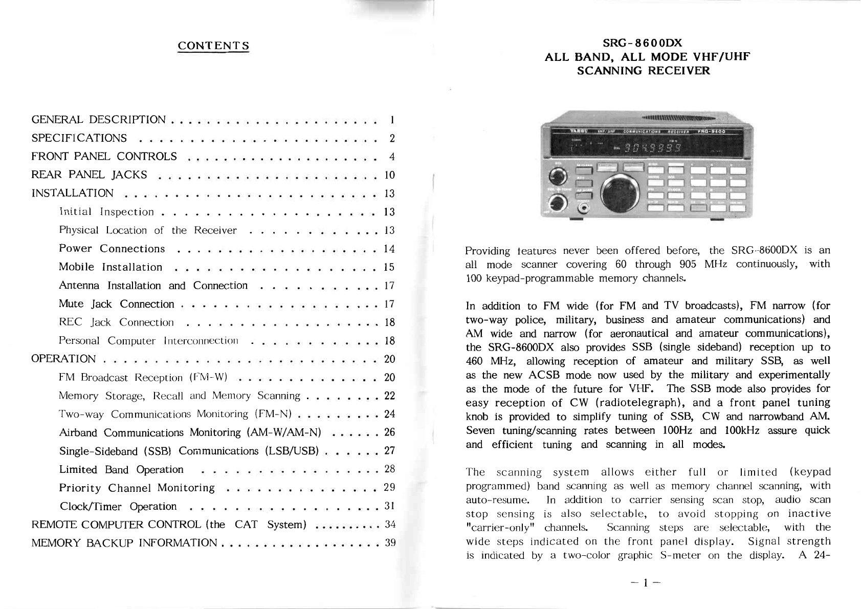
SRG-8600DX
ALL BAND, ALL MODE VHF/UHF
SCANNING RECEIVER
_.;.;.
.;;;.;.
_
I
a_„__i|
‘
“j
(”7
_
_
Providing
teatures
never
been
offered
before,
the
SRG—SGOODX
is an
all
mode
scanner
covering
60 through 905 MHz
continuously,
with
100 keypad—programmable
memory
channels.
In
addition
to FM
wide
(for
FM and TV
broadcasts),
FM
narrow
(for
two-way
police,
military,
business
and
amateur
communications)
and
AM
wide
and
narrow
(for
aeronautical
and
amateur
communications),
the
SRG—SBOODX
also
provides
SSB (single
sideband)
reception
up to
460
MHZ,
allowing
reception
of
amateur
and
military
SSB, as
well
as the
new
ACSB
mode
now
used
by the
military
and
experimentally
as the
mode
of the
future
for VHF. The
SSB
mode
also
provides
for
easy
reception
of CW
(radiotelegraph),
and a front panel tuning
knob
is
provided
to simplify tuning of
SSB,
CW and
narrowband
AM.
Seven tuning/scanning
rates
between
100Hz
and
IOOkI-Iz
assure quick
and ef
ficient
tuning and
scanning
in all
modes.
The
scanning
system
allows
either
full
or
limited
(keypad
programmed) band scanning as
well
as memory channel scanning, with
auto—resume.
In
addition
to
carrier
sensing
scan
stop,
audio
scan
stop sensing
is
also
selectable,
to avoid stopping on inactive
"carrier—only"
channels.
Scanning
steps
are selectable,
With
the
wide steps indicated
on
the front panel display. Signal strength
is
indicated
by a
two—color
graphic
S—meter
on the
display.
A
24—
_1_.
CONTENTS
GENERALDESCRIPTION...-.—........-.i.._....;.a-..
SPECIFICATIONS
.
.-
.--..-
.:..
ii
.--
.
-.
. . .
...
. .
.-
.
......
.
FRONT PANEL
CONTROLS
.-
g
.
-
‚_
.,
..
..
.
..
.
.;
.
-_-_
..
.
.;
_.
..
REAR
PANEL JACKS . .
.-
, .
‚.
.
..a”.
;
.;
.
-._„.
_...
.
INSTALLATION .
-.
. . .
...}.
. . .
..
...-...
.=.--.-
41-"
Initial
Inspection
..............
. .
-.
;.
Physical Location
of
the
Receiver
. . . . . .
_
„.
. . .
_.
Power Connections
.....
-
. . .
.-
. . .
.»
..
...:
.:
-.
_.
_.._
‚.
Mobile Installation . .
-.
. . .
‚.
.
..
.
.-
.:
.. . . . .
Antenna
Installation and
Connection
. . . . .
-.
-.
.
_.
„.
Mute Jack Connection. . . . . . .
..
.-
.
.,
.
._
..
REC
Jack
Connection
. . . . . . . . . . .
.-.
.
..
...-.
Personal
Computer
Interconnection . . .
.-
-.-
. .
-.
_-._.
‚_
. „
OPERATION........--.........._‚...-._.‚._.._
FM
Broadcast
ReceptiOn
(FM—W)
.
-.
.: .
..
. .
-.
-.
g.
a:
.. . .
Memory
Storage,
Recall and Memory
Scanning
. . . . . . ,
._
Two—way
Communications
Monitoring
(F
M—N)
. . .
“.“
.
;.
..
.
-.
Airband Communications
Monitoring
(AM-W/AM-N)
-.
. . .
a
.
Single—Sideband
(SSB) Communications (LSB/USB) .
‚;
. ,
Limited
Band
Operation
. . . . . . . .
.:
.
.—.
. . . .
-.
.
Priority
Channel Monitoring .
a
-.
. . .
;:
-.
. .
-.-
..
Clock/Timer Operation .
._
. . . .
._.,_-.
‚.
..
. . . . .
-.—-
. .
4
10
13
13
13
14
15
17
17
18
18
20
20
22
24
26
27
28
29
31
REMOTE
COMPUTER
CONTROL
(the
CAT
System)
. . .
.;_.-.-;.-
.-
. .
34
MEMORY BACKUP INFORMATION
.-
.
—
.—.-
.
a-
..
. .
.-
.-
i
=.
:-.-
r .
‚=.
-.-‚-
-.-
39
SRG—8600DX
ALL
BAND,
ALL
MODE
VHF/UHF
SCANNING
RECEIVER
Providing
features
never
been
offered
before,
the
SRG—8600DX
is an
all
mode
scanner
covering
60 through 905 MHz
continuously,
with
100 keypad—programmable memory channels.
In
addition
to PM
wide
(for
FM and TV
broadcasts),
FM
narrow
(for
two-way
police,
military,
business
and
amateur
communications) and
AM
wide
and narrow
(for
aeronautical
and
amateur
communications),
the
SRG-8600DX
also
provides
SSB (single
sideband)
reception
up to
460 MHz, allowing
reception
of
amateur
and
military
SSB, as
well
as the
new
ACSB
mode
now
used
by the
military
and eXperimentally
as the
mode
of
the future for
VI—IF.
The SSB
mode
also
provides
for
easy reception
of
CW
(radiotelegraph),
and
a
front
panel
tuning
knob is
provided
to simplify tuning of
SSB,
CW and
narrowband
AM.
Seven
tuning/scanning
rates
between
100Hz and 100kI-lz
assure
quick
and efficient
tuning
and
scanning
in
all
modes.
The
scanning
system allows either
full
or
limited
(keypad
programmed) band scanning as
well
as memory channel scanning, with
auto—resume.
In
addition to carrier sensing scan stop, audio
scan
stop sensing
is
also selectable, to avoid
stOpping
on
inactive
"carrier—only"
channels.
Scanning
steps are selectable,
with
the
wide
steps
indicated
on
the
front
panel
display.
Signal
strength
is indicated by a
two—color
graphic
S—meter
on
the diSplay. A 24-
__l_.

:mxmmam
fiEmtfl
mmim
6320
E0
82>
98:1o
.5:
UTE
:0
58:
-o:
:o:m:#<&
was}.
:35
00.9:
”25:00
0:96
0:05
020mm
80:82
2502
8-s
25.:
0:00
$.50.»
00
A898
00:086.
083
“00:88.00:
00::00m
80.0%
0.55:3
:2
3;
m:
N:
08:25
:58
om: ..
ow
x
om:
”A
0:20
8:.
080
E0xom£
.088
<0
m
to
30000
US
<8
00:
to
£0086
830$
A80EUEEV
<8
0mm
838000
”80:80
30000
826.”:
>2
1
N:
UQ
"
mm:_0>
baa—00
:030&
5:8
000:
00::
m8:
:83
08:0
w
00::
2:
800000
0:00....
00:
”20:00:”:
@0802
E8008
:0
850%
00.08
00:00:09.
NI:
:\
N:
00:
mmw
:2:
mm
\
8m:
\
0:
\ m
£5-24:
NI:
:\
N:
00:
2-37:.
NI:
8:
312::
.
:0:
mm
\
mm:
\ 2\
m
.202:
.38.
05:0:
22%
m8:
.6:
>03
mwm
A : : :V
>5mé
3:26:
AZ\Z+m
m8:
:0:
>004
212......
A : z :V
>304
>>I2h~
54:m
m2:
:0:
>0m.o
ZISE
”b_>_0:w:0m
8083.
808:3
mvov-
NEE
mom
I
om:
08:90
mcom-
N02
0%
I
8
"808.5:
088
4a
..
IINII
:0:
mm...
8...
N02
:2
.300...
@0582:
0300885
0:5
82>
it
E50000
285
E-_>E
2080
5mm
.32.
.2125
with
“880:8
00:83:00
Em
NI:
:5
mmm
Em
NE
3
00E
32.
Em
N0:
v.9
:6t
2,...
Em
NI:
8:
HE E:
Em
E:
m:
3882
2:
”50:38am
m8
.88:
5mm
:0:
N22
02:
0:
00V
:32
momlow
”0mg:
55000:“:
ammmmmmZOHP/xU—h—Um—n—m
mammmm
40:00
:00:
0::
:0
0:00.:
0003
0::
0:
00:00:08
88:08
000:,
0
5:3
308:0:
UmFZV
00.00003
>8
:0
:030000:
@5323
.00500
:0
00
00:08::
00
0.0.0
:88
8:3
n:
0005
>8
6.
.20:
8
$3000:
0::
0:085
0:200:
:0
80::
030208
0:08:06:
U<
00.800
wig“:
800300
0::
:0
0:0
008000:
XDoowwuomm
0::
530.800
Ox:
:0
r,—
.083
83:00::
H<U
Er:
080%
0
0::
880800
8:00:00
>000
808
w:_m0
.0808?
9:8:Q
00::
-80800
0::
.w:_:0:
03:80:00
.9800
80808
038090
.2023:
00
£000
683:8
8
803000.:
6:800
00880800
0088200
3800:?
000
00
0:30:88
8:00:00
:85
0:000:30
wEBozm
.XQoowwuomm
0::
8
000
on:
0:
0:02
8:800
000:8
0
00030::
80:86
.50
0000:»
05.
$88008
0:000:80:
:0:
00:000.:
030
m:
00:00::
m::::008
2308
<
6:280:00:
880%
:0:
0:02:08:
00:00:
:30
80::
0030::
0:
:83
0:3
0.0.0::
:0:
:0
000300
0:30:
:85
8:80:00
0008088
808088
:0:
08:90
8:800
:050
0:0
308
mm
0:0
:2:
.8900
A0005
3?:
00:28:08
£00300
:030200
0:00
000
0030::
00:00.:
8:03:03:
.083
.80
:0
80:88:88:
:0
@8800:
0::
$8386
.3080
:oEo:
0:880:00
:0:
.000000
50:80:
0
5:?
m:0_m
60030::
0:
8835620
:00:
hour
clock/timer
is
included,
along
with a
recorder
output,
for
automatic
power
on/off
switching
and
recording
of
transmissions
at
any
time.
Additional
jacks
provide
cpu band
selection
outputs,
multiplexed
(FM
wide) output, AF and RF mute and other control
signals
for maximum
expansion
potential
with future
options
or for
those
who wish to
provide
their
own
add-on
hardware
for
special
applications.
A mobile mounting
bracket
is
also
supplied
for
automobile
mounting.
The
Yaesu
CAT
System
provides
a
direct
control
link to the cpu in
the
SRG-8600DX,
allowing
operators
with
personal
computers
to add
virtually unlimited
customized
control
functions
in
software,
such
as
multiple,
organized
memory
banks,
automatic
tuning,
and
custom-
ized scanning
systems,
using most
any
personal computer and a
Yaesu
FIF
CAT
Interface
Unit.
For AC Operation the
SRG—8600DX
requires
one
of the
Optional
PA—4
series
AC Adapters, available
from
all
dealers
where
the
receiver
is
sold.
A
TV
Video
IF
Unit
may
also be installed as an option,
allowing reception
of
TV
pictures (NTSC format)
with
a video
monitor
connected
to the
video
jack on the
rear
panel.
§§§§§§
SPECIFICATIONS
§§§§§§
Frequency range:
60—905
MHz
(up
to 460
MHz
for
SSB)
Modes, 3dB
Bandwidth:
FM Narrow
(15
kHz
BW)
FM
Wide
(180 kHz BW)
AM Narrow
(2.4
kHz
BW)
AM
Wide
(6
kHz BW)
SSB
(2.4 kHz
BW)
Conversion
schemes:
Triple
(F
M—N,
AM, SSB)
Double
(FM—W)
Single
(Optional
TV
Video
Unit)
Intermediate
Frequencies:
47.754,
10.7 MHz and 455 kHz
__2__
“:|—_
Image
Rejection:
60
-
460 MHz
—50dB
typical
460
-
905
MHz
—40dB
typical
Typical Sensitivity:
FM—N
0.5uV
(for
12dB
SINAD)
FM—W
1.0uV
(
"
"
"
)
AM—N
1.0uV
(for
lOdB
S+N/N)
AM—W
1.5uV
(
"
"
"
)
SSB
1.0uV
(for
15dB
S+N/N)
Tuning
steps:
FM—N*
5
/
10
/
12.5
/
25
kHz
FM—W
100
kHz
AM—N
100
Hz
/
1
kHz
AM—W*
5
/
10
/
12.5
/
25
kHz
SSB
100
Hz
/
1
kHz
*Selected
steps
shown on display
Memory
channels:
100
Audio output:
1W
(into
8
ohms,
with
less
than
10%
THD)
Power
supply
voltage:
DC
12
—
15V
Power
supply
current:
Operating
550
mA
(maximum)
Power
switch
off
100
mA
DC
supply
off
3
uA
max.
(backup)
Case
size
(WHD):
180 x 80 x
220
(mm)
Weight:
2.2
kg
(4.9
lb)
without
options
Supplied accessories:
Whip
Antenna
(0.6m)
DC
Power
Cord
(1.8m)
MMB-28 Mobile
Mounting
Bracket
Wire
Stand
Q:)tions:
AC—DC
Wall
Adapter
(PA—4B
for
110-
120V,
or
PA—4C
for
220—240V)
Video
Unit
(NTSC)
SP—55
External
Speaker
lmll
I88
80::
80::
83000:
0::
80:08
0:
.08080
0::
80::
08:80
:0
8
:08:
0::
00000800
8:8:
:03:
00%
:03300003:
03:8
38:00:08.3
8.6:
8:
0:800:
:00:
:0...
08:0
mm
0:
080:0
00:0:0000:
0::
8
0800008:
.0080800
:3
8030000
8:880
:0
808000
8:88:
0::
0080030
80.:
0:::
0:::
mg:
0
w:_::00::
0:00
:8:
E
030:0
20:00:08:
0::
00:00:00:
:05
80808080
8::fi
.80.:
0:::
0:
00:00::00
0:
>08
.038
:00800
um
:0
IN
0
8:30
:85
88:00:00:
00:0:0
:0
8:00:08
0:00:05
0020::
:0:
0:08:00
00:0:
5008::
:08
888:0
80008008
0830
0>0:
:0::
08:90
000::
:0
3:0
00:0
:05
8::000
0::
00000800
0:
:0850
0:::
8:3
.8039:
.3
0088008
0:
:3
:0:
:0
8:8:3
00:00:00
0:
8:80
80
8.88:3
00:0
:33
8::000
0::
:0800:
A80:
000008008:
0::
:3
:03:
30:00
008808
0::
0:00:00
8:8:
:08
00:0.
:0::_00:-03:
08:.
250
8 E
008030
0:
:0:
:05
0:03:05:
03:00:
80808
0:0
8832008
0::.
.000:
88:
:0:
0:
:3
8:?
83000:
0::
to
:0850
0:
030.820
0::
08:
0032580888300
38.:
8:800
0::
0:0:0m
008580888000
:00
0:
8:800
40w
0::
:08:
008:
:0
8:80
0
:0
0880>
080::00800
0
:0:
00:03.80
0:
080:0
::
.83000:
0::
:0:
8:800
08:8>
0:0
8:80
“EO\ZO
:88
0::
0:
80::
:08:
0::.
8:0
83
00>
:0:
00:0>-00_>
0005
300888300
0:0
.0888:
000:
0::
83000800
83:08:
0005808
:85
.8800:
2008.0
N:
:0800
0::
80:0
0:
:00
0:
:3
3:08:07:
00:80:03:
080800800
:008
30:0
0:
.:03000:
0::
:3
83.3880
030:0
0::
8
080000:
000:
0:0
080::
0::
0:00.300
8:800
08:.
32.:
.38:
020:
E
.3:
0w0:
:0
a:
000:
0008
>2
.2“:
0::
:3
0080030
0:
8:800
0::.
.Ammm
.23
000300:
0:
:0
:25
08000008
008:
003000:
0::
08:3
88:
0::
0:
:03
0086808
00:0:0:
0:
.3088:
080:0
8:800
08:
838000:
32
0:0
2:2“:
88:0:
:0:
.8828:
000580888000
38:
:00
0:
080:0
8:800
08:
.3003
0:0
0000:0803
0:0:w30
:0
:00:
0:
80B
:0»
t
8:800
08:
8
:00
88:
08:88:
0::
:0::
:0m:0::0
0:
:0::
003000:
0:
8:90
0
0008:
030:0
:03000:
0::
0:08:
:083
.8088
:08300
0008
:0
0::
8
5:330:00
0::
0:00.300
8:800
08:.
300.00:
:00
E
.2
0m0:
:088:80:
.8808
03::
8:03800
__:o_:0=0:0::=
0::
000:
00008
.83000:
0::
0:
830:
0880800
0:08“:
mAOEPZOU
Am-Zxxn—
.HZONE
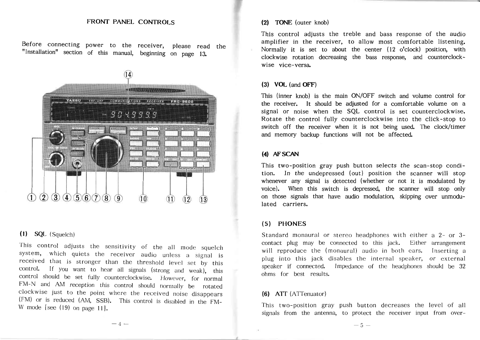
FRONT
PANEL
CONTROLS
Before
connecting
power
to the
receiver,
please
read
the
"Installation" section
of
this
manual,
beginning
on page
13.
(
1)
SQL
(Squelch)
This control
adjusts
the sensitivity
of
the
all
mode squelch
system, which quiets the
receiver
audio unless a
signal
is
received
that
is
stronger
than
the threshold
level
set
by
this
control.
If
you
want
to
hear
all
signals
(strong
and
weak),
this
control should be set
fully
counterclockwise.
However,
for
normal
FM—N
and
AM
reception
this control should
normally
be
rotated
clockwise just to
the
point
where the
received
noise disappears
(FM)
or is
reduced
(AM,
SSB).
This
control
is
disabled
in
the FM-
W
mode
[see
(19)
on
page
11].
I
uI-I-Inqimb.
(2)
TONE
(outer
knob)
This
control
adjusts the
treble
and
bass
response
of
the audio
amplifier
in
the
receiver,
to allow
most
comfortable
listening.
Normally
it is set to about the
center
(12
o'clock) position,
with
clockwise
rotation
decreasing
the
bass
response,
and
counterclock-
wise
vice—verse.
(3) VOL (and OFF)
This
(inner
knob)
is
the
main
ON/OFF
switch
and
volume
control
for
the
receiver.
It
should
be
adjusted
for a
comfortable
volume
on a
signal
or
noise
when
the SQL
control
is
set
counterclockwise.
Rotate
the
control
fully
counterclockwise
into the
click—stop
to
switch
off
the receiver when
it
is not being used. The clock/ timer
and memory backup functions
will
not be
affected.
(4)
AFSCAN
This
two—position
gray push button
selects
the scan—stop
condi-
tion.
In
the undepressed
(out)
position the scanner
will
stop
whenever
any
signal
is
detected
(whether
or not
it
is modulated
by
voice).
When
this
switch
is
depressed,
the
scanner
will
stop
only
on
those
signals
that
have
audio
modulation,
skipping
over
unmodu-
lated
carriers.
(5)
PHONES
Standard monaural or
stereo
headphones
with
either a
2—
or 3-
contact
plug may be
connected
to this
jack.
Either
arrangement
will
reproduce
the (monaural) audio
in
both
ears.
Inserting a
plug
into
this jack disables the
internal
speaker, or external
speaker
if
connected.
Impedance of the
headphones
should be 32
ohms for
best
results.
(6)
A'IT
(ATTenuator)
This
two—position
gray push button
decreases
the level
of
all
signals from the antenna, to
protect
the
receiver
input from
over—
__5__

[hill
.003000
=00300000=
000
00m
0000000
003
000808
0000
000000
00000000
0000
003
00000
005
000
0000000
000:
0000
00B
0000
000808
000
00
00
:05
00300000
00000500000
00000000
000808
0000
00
00
:05
00300000
000808
.000
0000
0800000
000000
00
00000
00
000800
0000000
000808
0090-030
0
00
.00000
005
000
00
000000000
00000
000000
0008002
0000
000808
0
00
00300000
0000000
300000
0008020
~02
.003000
=00300000=
000
00
0000600
000
000000
00000.00m
0000808
00000
0
00
00>000
0000000
005
000
000
00000000
00
:05
00000
005
000
00
000:
0000
0008
000
000000000
00.0.
000000
000802
000
80000
00000
005
000
0000000
40:00
.0000
000
000000000
0000
00
2000802
00
00000
00000
00000000
000
0.0.0000
000
0000
000
0000
000000000
.000808
00000000
0000
000
8
000000
00
:05
0000
000
00
0000000000
00
00000
00
0008
000080
0300
0000000
000808
000.
.000808
0
00
005
8000
0000
0008
000
00000000
000
000000000
0000802000009
02
|Q
.0000000
000
003000
=0030
-0000:
000
00m
000000000000
00000
00
00300000
00800:
085.0
0000000
00000
000>0
00
$300
000
000808
000000.000:
00000000000
0
00000
0300000808
00000000
0000.
.000
000
00
0030000
w0000000
0000000
003030
03080000
000
0000m00
000000300
5—0
.000808
0
00
m00>00000
0003
0000300000
00
000
MODE
000.
00000000
000
0>000
000.0
000000000
00
0008
00000000
00
0.
FRIET
2-2010081!
2-0211
000+
001W.
”030000
00
00008
000
0w=0000
000000
000
0000
00
m0000000
00000000
.00000
0000
000
00
w00>00000
0003
000050000
0:
000
0000
00000000
00000000
000
0000000
MOOS—
.00000
0008002
000
00
008.3
:0
00
000
.0008
.0000»
2.0
000
00
00000000
00
000
0000.
«00000000
000
00
0000
00.000
000
00
03000
00
00008
030
000000
._000.00.
000
0000.
00000
0000000
020
000
0005
S000
000
00.00
mm
00
m.m0
.2
.m
000
300000
IQ]:
SE
000
mmD
£60
000
00.3:
00
0:000
000
0000.0.
.00000
005
000
00
000000000
000
0000000
000
00000
0000000000
000
0000000
050%
.00000
0000000000
0000000
000
00
0000000000
000
00
0030000
0000
0000000
00003000
000
00
00000000
000
.0000000000
00000
00
00000
00000
0050
00
00
.00000
000
0000
0000
0 00
.00003000
00
0000
00000
00
000000000
0030000
000
00005
00:00
:05
0000
<
000!
000000000300002
=08m
8:
.0000000
000
0000000000
00
000w0
0000
00000
00
000000
0000.0
00003000
00
:03
0000000
000
608000800
0000
0008
000
0000
000
0000000
00
.00000
000802
000
00
0003
0000000
000808
00000000
00000
000
00
00
.00000
005
000
00
00
00000000
000
00005
0000
m00000
000
00
0: 00
00500
0000000000m00>00000 000000000
000
0>08
0000
00:0008
0m000
0050
00000
.0300000808
0000000
00
0000
n5
000
20500
80
08008
0000
80
0002
0000
00
0000800000
000
00000
90000.
00000808
000
0w00000
00
.00000
0000
000
00
0000
000
000000
w00000u0000
000000000000
03000
0000
000.0.
005—
w00000.
03
.00000
0000
000
00
w00>00000
00005
00000000
00
000000
000.0.
.00000
005
000
8000
00
00
0000000500
00
0000
:00:
00000000
000
00
000009
0000
0000
00000>
00
0000
:05
000808
000.0.
.00000
0000
000
00
00300000800000050
0200000800000
.005
000
00
0000
0008
000
00000000
000
0000
100000
000
000000
:05
0000
00
0000000
0000
8000
0000
:0
000000
0000000
000808
0
00
w00>00000
0003
000000
000m
0000
90000000
0800
055020
000000
E E
0000000000
00000000
8080008
w0000>000
.000000000
000
00
0000000
0000
00000002
000090
000000
000>
00
w000000
loading by
very
strong
signals.
Normally this button is not
depressed,
providing
maximum
receiver
sensitivity.
(7)
M
CLEAR
(Memory
Clear)
Pressing
this gray button when
receiving
on a memory
channel
clears
all
data
from
that channel
(a
beep
will
sound)
and
trans—
fers the
frequency
and
mode
data to the Dial,
automatically
switching
reception
to the Dial
state.
That
memory
will
then
be
vacant
(and
thus
ignored
by
the scanner)
until
data is rewritten
to
it
from
the Dial
state.
This button is disabled while receiving
in
the Dial
state.
(8)
Tuning Knob
This
knob
allows
convenient
step-tuning
across
the band
in
the
Dial
state,
or
through
the
memories.
Tuning
steps
are
determined
by the MODE and
STEP
buttons.
(9)
DOWN
and
UPkeys
If
pressed
momentarily,
these
two
large
metallic
keys
move
the
displayed
receiving
frequency
down or up by
one
tuning
step
when
the receiver
is
in
the Dial
state,
or to the next (stored) memory
channel
when
in the
Memory
state.
If
pressed
and held for
more
than a half—second, the
scanner
will
be
activated.
Press
either
of
these
keys
again
to
deactivate
the
scanner.
(10) Small
Metallic
Function
Keys
A
beep
will sound
when
any function
controlled
by
these
keys
is
activated.
If
a
beep
does
not sound, or
if
two
beeps
sound
in
quick
succession,
the function is not
activated
because
that
function is not
accessible
in
the
current
operating
state.
STEP
selects
the
frequency
steps
for tuning and
scanning
in
the
Dial
state.
These
are
lOOHz
or lkHz for LSB, USB and AM
__6_
"
In“!
narrow,
and 5, 10,
12.5
or 25 kHz for AM
wide
and FM
narrow
(step size
for
these
latter two modes is shown at the
right.
side
of
the
di'Splay).
This
key
is
disabled
in
the
FM
wide-
mode,
and at all
times
in the
Memory
state.
MODE
selects
the receiver
detector
type and
IP
bandwidth
when
receiving
in
the Dial
state.
Repeated
pressmg
of
this
key
cycles
through
the
modes
as follows;
rLsß
+USB
+AM—N
—-AM—W—--
I‘M—N
—-i-FM-W:I
The
selected
mode
is displayed just
above
the
frequency.
The
MODE key is
deactivated
when
receiving
on a
memory.
PR1 (Priority) toggles the automatic priority channel checking
function on and off.
This
function
momentarily
tests
a
preselected "priority" memory
for
activity every
three
seconds
during
normal
reception
on
other
frequencies.
See
the
Oper—
ation"
section
for
details.
D
—
M
(Dial—to-Memory)
transfers the frequency and mode data
from
Dial to a memory. The memory channel
(two
digits) must
be
keyed
in
beforehand
or the
data
will be
stored
in the
last
selected
memory.
Pressing
this
key
does
not
change
the
selected state
(Dial
or
Memory);
it
only
transfers
the data.
DIAL
selects
the Dial
state
(from
the Memory
state).
The
frequency
and
mode
last
used
in
the
Dial
state
will be
recalled
(so the
Dial
actually
serves
as a lOlst memory).
Specific details are provided
in
the "Operation" section.
MR (Memory Recall)
selects
reception on a memory (the Memory
state) after receiving
in
the
Dial
state.
If
a
two—digit
memory
channel
number
is
keyed
in
before
pressing
thlS key,
memory
operation
will be on
that
memory
channel;
otherw13e,
operation
will be on the
memory
that
was
last
used
(before
the
Dial
state
was last entered), unless that memory was cleared.
See the "Operation" section.
__7.—
mga
0mm
.xn__>.
man
omo_>
m5:
>m+
8:390
.
.
a
.mEOQmm
888%
:2.
.m
.30
wmEESEwD
ommm
meg
mxaw
kxm
_
__H._;.
m3_a-_c_E
mcocanmmz
_m.5mco_>_
mZO_._.0m_ZZOO
034.”.
.8...
8:3
£3m
:28
98
.voxmfiflv
m.
7....
.8.
083
.28
889:
8533020
on“
E
608388
8.8
828:3
.883
085
8:3
8:550
@0888
one
98%..
“ma
nice—m
0.8
.HEO\ZO
8
«.50
808888
0.8
885
can?
zocmwscmz...
8cm
namumlumn
on“
:80?8@
woumBuE
fl
flin—
8
3E
.33..
on“
8
893338
3
.8288
8:320
.CoEoE
398$
2:
888
88:82
9:
E
9:382
855
5t
88:80.;
of
88%
85..
808085
288
838000..
9:
5:3
.888
05
E
88:88.:
98
52
of
2...
88085
namhwupmn
880$
05
so
camcobm
8:w
803008..
8288..
on“
2.8%
3—3.8
on“
838008..
83mm.
wEEQ
3&8
.3.
83.?!
85
co
3&8
883
89:88
on»
E
9:o
83m
88:
to 8
=0
28
808
9.:
8m
8
.8808
8835808
on”.
E
.28
3398
m.
.83
emcee
£5.
Eg
8:
.88:
“75-82...
85
m2m
8x
:9.
on”.
288
828
“£020
.883
on»
E
.9883
830:3
2:888
85
E
8302m
83000..
IJWI
05
.0
388
wczmgoao
05
o»
wEEooow
.wESOw
.883E008
8
8:850
8880:.
c3833.:
8
528
26:...
982
2.88::
9C.
:8.o
E...
a
-
_
.98—
Efiov.
333
a:
.to
28
:o
.883
20-838
05
Qmwou
8
5.9.7.5
z?
.5
E9.
cam
$5.08
28%
a
5.5
$2...
Emma
2..
5:3
mg:—
.888...
[#520
85a
85
E
.98
Em:
fl
828:3
:0
88C.
2F
83mg
85
co
33$...
.3
3888.
some
8.6:
85
8&8
82.88::
.0
83280c
9.5:...
8x
8:3
25
.8
228:3
896
.820
9:.
E0
.882.
”w
bucm
.820.
.20.
MU
=3
.82
3.8%....
5.3.08
gm
8:5...
.6.
RE
823:
0%.
its
...:c._uu::_:ou 5
80m:
03.8
.m_
.882”.
35.
4.02.8.3
beams:
85
a:
835
2888..
E?
3%
@8885
fiflwto
85
85....
6.338
fl
.3:
E5
.833
85
as.»
3
832%
an
mama—m
:E
839.30
8.888%.“
on
:2...
.0882:
383$
3.8:.
05
.8
Jam
5
38:
3
.38
3&8
8:838
@8888
888
85.
.85
ma...
5.
3%
38338
$323.88
._.m._n_
one
B
58888
Sat
3%
835
we...
8:83.88
05
$8858
:mfiuofbofiog
D
I.
2
.2888
0.88
8..
8:58
min.
.8
:28m
..coEm..oaO..
on»
mow
£2
8
1:30
888
.8828
8.838.;
3
F888
28
388
8833020
2:
388
o._.
I.
_.
__
o.
.......T
92F
F8...
£23
20....
HEEL
38:88
05
.8
.8800
05
E
88808
BwEm
w
.8
82%;”.
.3
808085
.288
82%
:O\.CO
88c.
85
8838.”.
0.88
mono
£0040
wEmE
8o
:O
88:.
05
8
8:86
fl
2033
.288
to
8:5.
85
88288
Ewmw
M0040
mmmi
.382qn
:o
8:836
on
:25
8380..
8:”—
2033
pm
883
on“
Co
mfifiwwog
26:...
8:3
98338
5033
.0808
:0
8:5.
or:
8838...
Emma
8x
M0015
on”.
wEmm
.Gmenmx
2.88::
85
.3.
9:3
or:
*0
9:3m
282m
28
.8828
820
2:
88388
3x
35
.0
30.8
8.5
05.
483888..
mascara
805?:
.0588
883E020
on“
98:88
MUOAU
CLOCK
displays
the
clock/timer
status
(without
affecting
reception).
The
first
press
of
this
key
activates
the
clock
display
and
allows
setting
of
the
time
(by
the
numeric
keypad).
Pressing
the
CLOCK
key
again
activates
the
Timer
On
mode,
which
diSplays
(and
allows
resetting
of)
the
time
at
which
the
receiver
will
be
switched
on
automatically.
Pressing
CLOCK
again
activates
the
Timer
Off
mode,
which
is
similar
to
the
Timer
On
mode.
Pressing
CLOCK
once
more
activates
the
Timer
Of
f/
On
select
mode,
indicated
by
display
of
a
single
decimal
in
the
center
of
the
display:
[-I-TIME
+ON
TIME
—-OFF TIME
—--"."
(DW)]
To
escape
the
clock/timer
status
and
return
to
frequency
display,
press
DIAL
or
MR.
See
the
"Operation"
section
of
this
manual
for
more
details.
M
-
D
(Memory—to-Dial)
transfers:
the
frequency
and
mode
data
from
memory
to
the
Dial,
overwriting
previous.
data
in
the
Dial.
The-
source
memory
channel
digits»
may
be
keyed
in
first,
or
the
-(
last)
seleCted
memory
will
be
transferred.
Operation
will
always
be
shifted
to
the
Dial
when
this
key
is
pressed,
and
the
original
memory
data
will
remain
intact
(in
the
memory
Channel).
This
button
is.
also
used
in
conjunction;
with
the
DOWN/UP
keys
for
Limited
Band
operation-‚..
described
later.
(11)
CE
[ON]
(Clear
Entry
&
Timer
On)
The
Clear
Entry
function
of
this
blue
key
allows
cancellation
of
numerical
digits
that
have
been
"entered
by
mistake
on
the
keypad.
The
Timer
On
function
is
used
only
in
the
timer
ON/
OFF
select
mode
(when
the
display
shows
only
a
single
decimal
and
"OFF"
or
"ON
OFF
"),
to
toggle
the
auto-ON
timer
on
and
off.
(12)
White
Keypad
Keys:
1
—
9
and
0
(OFF)
The
numeric
keys allow
entry
of
frequency,
memory
channel
or
clock/timer setting, according
to
the
operating status
of
the
_8.__
receiver
selected
by
the
metallic
function
buttons.
In
the
timer
ON/OFF
select
mode
the
"0"
key
toggles
the
auto—OFF
timer.
(l3)
'I‘IMER
SEl'
This orange
key
is
enabled
only
in
the
clock/timer
modes,
to
.set
the
clock
and
On
or
Off
times
after
keying
in
the
deSIred
time
digits
on
the
keypad.
(14)
Display
During
regular
reception
the
display
shows.
the
relative
received
signal
strength
on
the
2—color
bar-graph
indicator
at
the.
left,
and
frequency
in
the
center,
with
the
reception
mode
indicated
just
above
the
frequency
digits.
When
receivmg
in
the
Memory
state,
the
2-digit
memory
channel
number
is
displayed
at
the
right.
PR1
or
DIAL
is
indicated
between
the
bar-graph
and
frequency
when
these
are
activated.
OFF
or
ON/
OFF
are
shown
Just
above
the
memory
channel
when
these
timer
functlons
are
activated.
In
the
clock/timer
modes
only
time
(or
".")
is
displayed,
and
on/off
status,
when
set.
PLUG
CONNECTIONS
Signal
control
or
Stereo
Demultiplexer
etc.
EXT
SPKR
plug
'
-
ositive
voltage
{"
p
._
Signal
Tape
Recorder
Ground
+8v,
MUTE,
VIDEO
plug
MPX.
REC
Plug
00:20:02
02
2:3
002
>
20:02:00
0::
:00?
0200:20:020003000:
0250::
:23
30:00
002>
20>02
::0:0:00
0020::
:02?
a:0:::OU
E00
0:020:04
002>
0::
:0
::0:::0:.:00
030:0
:0:::00 02:0.
2008000003
UO<
>.:.
2v
.0285
0000:
0
0:
:0::00::00
:0:
302000:
0::
:2
00:20:02
02
:ED
002>
20:02:00
0::
:0:>>
2002
00:00:02
30:00
002>
0:0:000:
002>0:0
200.:
00¢
02::.
89>
:02
02.2200
0:0
:38
503:0:
0200::
0:00:
:23
02::0222
on
:0
0:::>E80
330808500
0:
20012
.3000?
80::
02:02:00
:05
0002020500
00:0:0
20::000 :0
:0:
.0000:
25:22::
0::
:22
:0:00:00
3.22::
0::
80::
30:00
00020::
200.:
0:0:0
22::
:00::00-N
02:.
2002:0252:
09:2
802
00:08
0:0
2:02::0:020
30:23:
3:00200:00:
0:
0:
2003
00:
0:0
:0::
20:90
0:0
0020:
:0::
00
:00
0:
0:00.50:
200:0
::
.3202
000::
21>:
r:
0::
20:00:
0:
:05
20:00
:02?
:0
:00:
20:00:::
:020000
0::
0:00
:0:::00
02:.
2005023083
EDS:
n2
8:
00200020
02
:020000
20::0:::
0::
200.:
0:::0:::00:00::
0:
02:0
0
00:3
02:0
:0:
0:
0
.20
0000002:0
:23
ammim
0000?
0::
00
:00
0200000002
05020
:0
00
:02:00::00
:00
0:
200.:
0:0:0
2:0:
:00::00-03:
02:9
2:02000m
2050:0022
fivEm E
3:
00:20:00:
02
:00:
02000
200800
00:3
00000::0
0200000
0:00
:0
0:20:80:
000:
:0:
”0:00:00
MZOH
0:0
15>
0::
:3
00:00:05:
02
:02?
5:300
00:0
08:22
80
>50:
08:000.
20>0:
::0:0:00
0020.203
200.:
02:9
00:
E2
032000
0:
:00::00
:0::00
02:.
000000
05000
050:6:
.5:
<58:
8
a:
0
0:00
00>
0
0228::
2%:
<0:
002:
>w
8:
20202.
T
.:E>>\2om_m
m
l©-u-—
+©--l—.
©
>I_n_n_3m
EM>>On_
OD
.0:0:::000:0
::0::00::_
0:0
0:20:00
:0:::::
:0:
:02:000
=:02H20220:0::=
0::
00m
.200.—
02::
.3.
0:400:20.
00:00::00
.mfl
:00:
:03:
00020.:
“lid
:0:
.02:
0:::
0::
80::
00020::
0:00:08
0::
30000
0:
000:
0:
:00
0:0:000<
:03
00-
:0
mwéfl
20:02:00
0::.
002300
:0E2:\20020
20:0:
0:
0:::
0::
:0
00:00::00
0:
200:0
020000
0::.
.to
:0:3
<2:
00:
0:0
.:0
0:
:0>:000:
0::
:0:3
<2:
00m
0:
::0:::U
.200;
m: |
N:
02000:
0::
:0:
00020::
30000
00
0::
0:00000
200.:
200000
02:0
00>
0.02
:0:
:0
0
0.
.0
0_
0
.0
0
0.
0
0.
:2
wv_U<—.
AME/0%.“:
EM
REAR
PANEL
JACKS
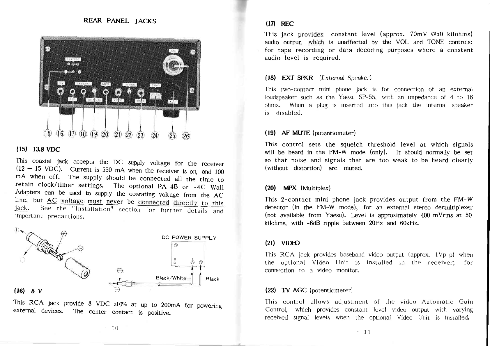
(15)
13.8VDC
This
coaxial
jack
accepts
the DC
supply
voltage
for the
receiver
(12
—
15 VDC).
Current
is 550 mA when the
receiver
is on, and 100
mA
when off. The supply should be
connected
all the time to
retain clock/timer settings. The optional PA-4B or -4C
Wall
Adapters
can
be used to
supply
the
operating
voltage
from the AC
line,
but
159 voltage
must
never @
can-nested
directly
to
this
fl.
See
the
"Installation"
section
for
further
detafis—afi
important precautions.
DC POWER
SUPPLY
©
9
©
©
j'
"
l
“l
'
?
_
..
BIack/White—f‘flrBlack
"Y.-
(16) 8
V
@
This
RCA jack
provide
8 VDC
110%
at up to
200mA
for
powering
external
devices.
The
center
contact
is
positive.
(17)
REC
This
jack
provides
constant
level
(approx.
70mV
@50
kilohms)
audio
output,
which is
unaffected
by the VOL and
TONE
controls:
for
tape
recording
or
data
decoding
purposes
where
a
constant
audio
level
is
required.
(18)
EXT
SPKR
(External
Speaker)
This two—contact
mini
phone
jack is for
connection
of
an
external
loudspeaker
such
as the
Yaesu
SP—55,
with
an
impedance of 4 to 16
ohms.
When a plug is inserted
into
this jack the internal
Speaker
is
disabled.
(19)
AF
MUTE
(potentiometer)
This
control
sets
the
squelch
threshold
level
at which
signals
will
be heard
in
the F
M-W
mode
(only).
It
should
normally
be set
so
that
noise
and
signals
that
are
too
weak
to be
heard
clearly
(without
distortion) are muted.
(20)
wx
(Multiplex)
This
2-contact
mini
phone
jack
provides
output
from the FM-W
detector
(in
the
FM—W
mode),
for
an
external
stereo
demultiplexer
(not
available
from
Yaesu).
Level
is
approximately
400 mVrms at 50
kilohms,
with
—6dB
ripple
between
20Hz and
60kHz.
(21)
VIDED
This RCA
jack
provides baseband video
output
(approx.
l—p)
when
the optional Video
Unit
is installed
in
the
receiver;
for
connection
to a
video
monitor.
(22)
TV AGC (potentiometer)
This control allows adjustment
of
the
video
Automatic
Gain
Control,
which
provides
constant
level
video output with varying
received
signal
levels
when the optional Video
Unit
is
installed.
00
000000000
0
000000
.00>030I
0000000000
0
00
0000
00
000.000—
000
-0000
000
0000
00
.00000000
00
0000000
000
00
00000
00
0000000
00
000000
00000000
000
00000000
000000000
00
.0
000000
0003
00000090000
00
0000
00
0000-000
000
00003
0090000000
000000000
00
w00000000
00
w0000000w
000
00000800
000
000
“00000000
000000000
00
0003
0000
00
0030000
000
0000:
00000000
0000000
000
00
00000000
000
000000000000
0000000
00
00000000
00
0000000
00000
030
000
0000
0.
00300
w00000000w
-0000
0
0>000
02000000
00
000>
000000
0
.00
0000.0
00
080-000
000
000000
000
0D
000000000
0:005
00
0:0000000
-
0000000000
00
000000
00000000
00000
00000
000
00
000000
000
0000000000
00000
0000
000
00.0
00000
00000000
000
.0000
00
00
00
0000000
00000000
000
00
00000
.0000
000
000
0000
00
000000000
00
:03
00
000000
.00
000000200000
0000000
000
00000
00
0000
00
0000000
0000000000
300
0
000
00000
000
.00000
000
00000
000..
0000000
00
000
800-0m0
000.
00>0000~0
000
.00
00000000
00000000
.00000
000
000000.00.
00.0
000000000
w00.0000.
0.00.
0000.00
000.
.000m
500000000000
000000 00.00 00 0.00.0 00
00.00.0000
00>...
000
”.000
.0:
0000500
00000000
000
000.000
000
0000000000000
0000
03.00
0000?
000000000
00
0000000
00 000000 00 00000000
0000000
000
0000
00000000
.0000000
000
0000
000
00000
000
000000
0m00000
00000000
.00
00w00
000
000
00
0000000
.000000
000
.0000
0000-050
000
00300000
00000000
000000
00000000.:—
2000000
.0005
0000000000 00
0000000000
000000000
00
00
00.0000
00
000000.00.
000000000
00
00000
000
00000000
000
00
000.000
0000000000
.0050
00
080-000
000
000
000000000
00000
000
0:03
.000000
00300
000
00
00000000
000
w000000000
000000
0:30.000
0000000 0000
00000
00 00000
0000
000000
0000020000..
0.0000000
00
0000000
oowmsomm
000
00
00000008000.
00.00.00
mmwwmm
ZO~H<AA<MMZ~
mmammw
LEE
000.500
0.503
00000000
00.0
A.
E
235
.5:
00000-00
.50
«000-07..
0000-..:
0040
:00
>m3m
0
008.2%
..
0.2
.
0:
.0050.
.0
u
0.2
tD
m0<umm._.z_
EMFm>w
._.<O
Dmm<>
.0000
0000000
.0000000000000..
000
00w
000000000000
8050000
0000
0000
00
000000
00000000000000
000000
0
000
$00000
-0:
000000
000
0000
00
008
0000000
0003
m0000000000
0000.000
000.
.0000000
000
00
0000000000
000
00
000.0
00000002
0000.
0000.
PZ<
8N.
.
.om
0m00
00
03000
00
000-000
00000001000
0000
Mr
000
00
0000.
0000
000000000
00000800000000
0
000
0030000000
00003000
000..
209
0001.0
0000.
.05
000
.>om
00
000000
00
005
0000
0.000000,
0000000
0000
0.00000
...
.
.
__
0000000
0500
.0000
000
000.000.
00000
00.0
.0000
0000
000000
00000000
000.0
0000000
00000
0000.
0240
00
0000.0
0000
00
0w0000>
000
00000
000
0G
00000000000
0
0003.
0000000300
00
0000
00
0000-000
000
000000003.
0000
00
000.000
0000.
000.0
000
.00
00000000
00000
000
000000
000
w00000000.
00
a0.....00000
000
0:
0030000
000
000000000
03020
000.0
<Um.000h
0.52
an.
(23)
MUTE
This
RCA jack
allows
disabling the
receiver
(in
any mode") by
shorting
the
center
and outer
contacts
of the
jack.
This
should
be
done
whenever
the
FRG—9600
is
used
in
conjunction
with a
transmitter.
Do not
apply
any
voltage
to
this
jack.
(24)BAND
This
4,—pin
molex jack
provides
binary
band
data
(an
three
pins;
the other being signal ground)
for
possible future options.
Max—-
imum
open
circuit
voltage
that
may
be
applied
is
30V.
(25)
CAT
This
6—pin
DIN jack
provides
connect-ions
for a
microcomputer
interface
unit (such as the
Yaesu
F
IF-?-ser'ies).
Pin—out
is
shown
on
page
36.
I
(26)
ANI‘
This
type
M
coaxial
jack is for
connection
of the
antenna.
The
supplied
telescoping
whip antenna may be
used
for
casual
lis-
temng,
but a
proper
outdoor
antenna
should be used for Optimum
performance. See the "Installation" section next.
YAESU
CAT
SYSTEM
INTERFACE
UNITS
\
A"
PIN
1:
GND
2: N.C
3:
SI
(Serial
In)
4: N.C
5: S-Meter
6: BUSY
CAT
PLUG
FlF-ZSZC
PIP-65A
(for
RS-2320)
(for
Apple
II)
§§§§§§
INSTALLATION
§§§§§§
_
Prfoper performance
of
the F
RG—9600
depends
on
correct
inSt‘a-llation.
Please
take
time
to study this
section
carefully
before
connecting
the
receiver
to the
power
source.
While the
setup
procedure
for
the F
RG-9600
is simple, permanent damage to
the
receiVer
can
occur
if
improper
voltage
is
applied
or
if
external
connections
are
improperly
made.
Initial
Inspection
After
carefully
removing
the F
RG—9600
from the
carton,
inspect
it
for any
signs
of
physical
damage.
Rotate
the knobs and push the
buttons,
checking
each
for normal
freedom
of
action.
If
damage
is
suspected
write
down
your
observations
and
notify
the
shipping
company
(if
the:
set
was
Shipped to
you),
or your
dealer
immediately.
save
the
Garten
and
packing
material
for
possible
use
later.
.
Physical
Location
of
the
Receiver
The FRG-9600
can
be
located
just
about
any
place,
but
there
are
a
few important
factors
to
keep
in
mind for
certain
installations.
Of
course
it will be
necessary
to
keep
the top
panel
clear
if
the
internal
speaker
is to be
used,
and
necessary
space
for the
rear
panel
connectors
and
access
to the front
panel
controls
should be
considered
-
especially
in
mobile mounting. Do not
locate
the
FRO-9600
in
front of a
heater
vent
or
directly
above
a
heat-
generating
device.
There
are
two
other
factors
to
consider
in
certain
applications:
the
distance
to the
antenna
feedpoint
(when the
receiver
is
used
with an
external
antenna),
and the proximity and grounding or
shielding
of
computer
equipment (when the
FRG-9600
is
used
in
conjunction
with
same).
For optimum
reception
the
receiver
should
be
located
as
close
to the
antenna
as
possible,
so
that
the
feed-
line
length
is
kept
to a minimum.
However,
unless
a
computer
is

II
mH
I
m
Miami
a
.
w.
m
M
|\0
(“08%
N
oSwE
a.
:32:
m
In
LOP—mm;
”Hm—H—
85:
0528...:
Jr
auntsm
_
.
82:00.2
_
.wmlm—EE
8:0
:0
8382983
8:
8mm:
”.8:
8::
:0
8.50808
08
308:
megwmfi
8:“
8
88m
883:8
8:0
.8
830800
8%
:33
883883
2:00
3
88:3
8
88>
888:
m
:8:
88008
8
8:
200%
H:
8:
80:88:88:
33
@5888
38838
80:33
83380
38
:3
082885
8
8::
8388:
8%
.888:
9388::
8:008
wmum—EE
08:80.0,
8:”—
wEm:
83:8
3880m
8
E88
08
838808
338
88
20.580
08
8820
8::
88:3
8802
8
080%
.8388:
8:.
839$
383.388
0:88
838mm:
8
8:8:
980
E
8:32:
8
3:0
8:8
cowmIOME
8:9
532335
2322
.888
088%
80»
:8:
@3388
3
0:0
.888:
@3888
83.8325
E50
33
80205
mmlmm
8::
$888388
8:008
830:
8:”.
8.3
803808
3888mm
.8388:
508380
8:
8833”,,08:
8
0”.
8388:
8:0
08.:
0:08
.8
880m
8::
838:8
ooom
Lumm
8:0
8:
308880
88300
:8
3
888m
8538
$85
8:.
8
.>.HZ<~_~_<>>
m—Ih. Q—O>
QZ<
.HZm—EnZDOm—
m=.:.
MU<E<Q
1—1—25
wZO—PDARUM—Mn—
mam—IF
m>mmwmo
OH.
MMDAFQ
.FAn—n—Dw
NIH.
n—O
”ma—m
m>_.:m0n_
”mm—h.
OH.
Qm—FUm—ZZOU
w_
M041.
MMBOL
m—IH
LO
HU<HZOU
MMHZMU
m—IH
H<IH
Z—<.h~—m-U
”NV—<2
.v—U<_.
mum—30n—
m-Ih.
Oh.WHAO>
m—
Z<IH
MMOE
LO
MO<HAO>
UQ
.HUm—ZZOU
mm>m—Z
.N—m—>~MUm—M
m:.:.
to
M01:
”Hm—30n—
Amz<m
Edam—~—
m—IH
OH.MMBOL
U<
Magma—xx
MM>MZ
vvvvvvvvvvvv
OZHZN—(B
AAAAAAAAAAAA
.880
:8:
8::
0”.
m2:
830:
8:”.
838880
88.8:
“EC
0”—
8w
3
30.580
15>
8:0
85
5380
8»:
48888
8
:33
8388:
8::
8:
0888:
8:
3
338—00
8:“
8::
0:0.
68$
8::
‘8
:8
.888
8::
8:
20:
83m
88:80
8:”.
8:
88880
3::
8:
8w:
3
8:“
m3:
8:“
8:”.
:8080
882
.888
DD
9:
‘8
830
a
8::
00
88880
8
82:
8388:
8:0
:0
80..
8300
DD
>92
80800
8::
:0
:8
888
83;
.8880
2::
8:08:
8
83880
m3
088
8
:33
8:”.
8.80m
UQ
8:8
8
3808:
38
8::
88m
8
0m
£0
3
.8388:
8:0
8:3
838.88
8830\808
8:
(802
08
.8
3
8388:
8:0
8:3
«803
8:88:
oowmlomm
85L
.38
U<>ovmuomm
:85
8w:
.8:
3
08¢»:
8::
23:3
02:0
06509.02
:85
mm:
8.:
fl
mvéfl
85
.888
U<
8:0
80.:
8388:
8::
838800
:83
8880
UQIU<
Owl/E
8
mvl<n3
380380
8:0
80.:
8:008
88::
83:3
.0D
38>
m3
0:
2
:83
838880
8:
080388
3
oowmlomr:
8:,w
mQOmHUOH—EOU
MORGAN—
.880800
0:8
8888
.8388:
8:0
:0
888803
.888
”:8:
8::
858880
0:
5888:
8
8::
£83888
0:88
28-8.:8
:33
88:80
£83800—
088t8
8.88%
:_
:0_8:8E_.8:xm
.8508
8:0
00
808
88>
88
>85
3
880800
8:”.
:8:
88:
83803830
0:
x08
88
8888
8::
“880
88:
my
88:
mm
8:
822cm
:83
L
T
well
shielded for RF noise
(a
rare case), the antenna may pick up
objectionable noise
from
the
computer
if
they
are very close to
one another.
Experimentation
in several different locations, perhaps
with
different ground connections, may be
necessary
to determine the
best
overall placement of the receiver, antenna and computer.
Power
Connections
The F
RG—9600
is equipped for operation
from
12
to
15
volts DC,
which may be supplied
from
the optional
PA—4B
or
PA-4C
AC-DC
adapter when operating the receiver
from
the AC mains. The
PA—4B
is for
use
with
110—120VAC
only, while the
PA-4C
is for use
with
220-240VAC only.
The F
RG—9600
requires 550mA when the
receiver
is on, and
lOOmA
for
clock/timer operation
when
the receiver is off,
so
be
sure that
any battery or
other
DC source
that
will
be used is
capable
of
handling
this
current.
The
center
pin of the
coaxial
13.8V
DC
power jack on the receiver must be connected to the
Eigitive
side
of
the DC
source.
Make
certain
that the plug
that
is
used
for
this
connector
has
the
correct
size hole for the
center
pin of the
jack, and that the
polarity
is not reversed (or the
receiver
will
be
damaged).
Be
certain that
the
VOL
control is
set
to OFF
before
connecting the power plug to the rear panel.
>>>>>>>>>>>>
WARNING
<<<<<<<<<<<<
NEVER
APPLY
AC POWER TO
THE
REAR
PANEL
POWER
JACK OF
THE
RECEIVER.
NEVER
CONNECT
DC
VOLTAGE
OF
MORE
THAN
15
VOLTS
TO
THE
POWER
JACK.
MAKE
CERTAIN
THAT
THE
CENTER
CONTACT
OF
THE
POWER
JACK
IS
CONNECTED
TO
THE
POSITIVE
SIDE
OF
THE
SUPPLY.
FAILURE
TO
OBSERVE
THESE
PRECAUTIONS
WILL
DAMAGE
THE
EQUIPMENT
AND
VOID
THE
WARRANTY.
The
SP—55
External
Speaker is an optional accessory for the
FRG-
9600,
allowing the source
of
audio from the receiver
to
be
repositioned
for
optimum
hearing.
ESpecially
practical
'for the
noisy mobile environment, the
SP—55
includes
its own
sw1vel-type
mounting
bracket,
and is available
from
your Yaesu dealer.
Mobile
Installation
The
FRG-9600
must
only
be
installed
in cars
having
a
negative
ground
electrical
system. The
receiver
should
be
located
where
the
display
and
controls
are
easily
accessible,
and
should
.be
securely
affixed
using
the
supplied
MMB-28
mobile
mountlng
bracket.
The
receiver
may be
installed
in any
position
w1thout
adversely
affecting
its performance, but it should not be mounted
near a heater vent or where it could
interfere
with
safe Operation
of the vehicle.
Refer
to the diagrams below and procedure on the
next page for
installation
of the
MMB—28.
.
_
Mounting
!.»
-
Surface
\ Mounting
Knob
Flat
washer
Remove
Figure
3
Figure
2
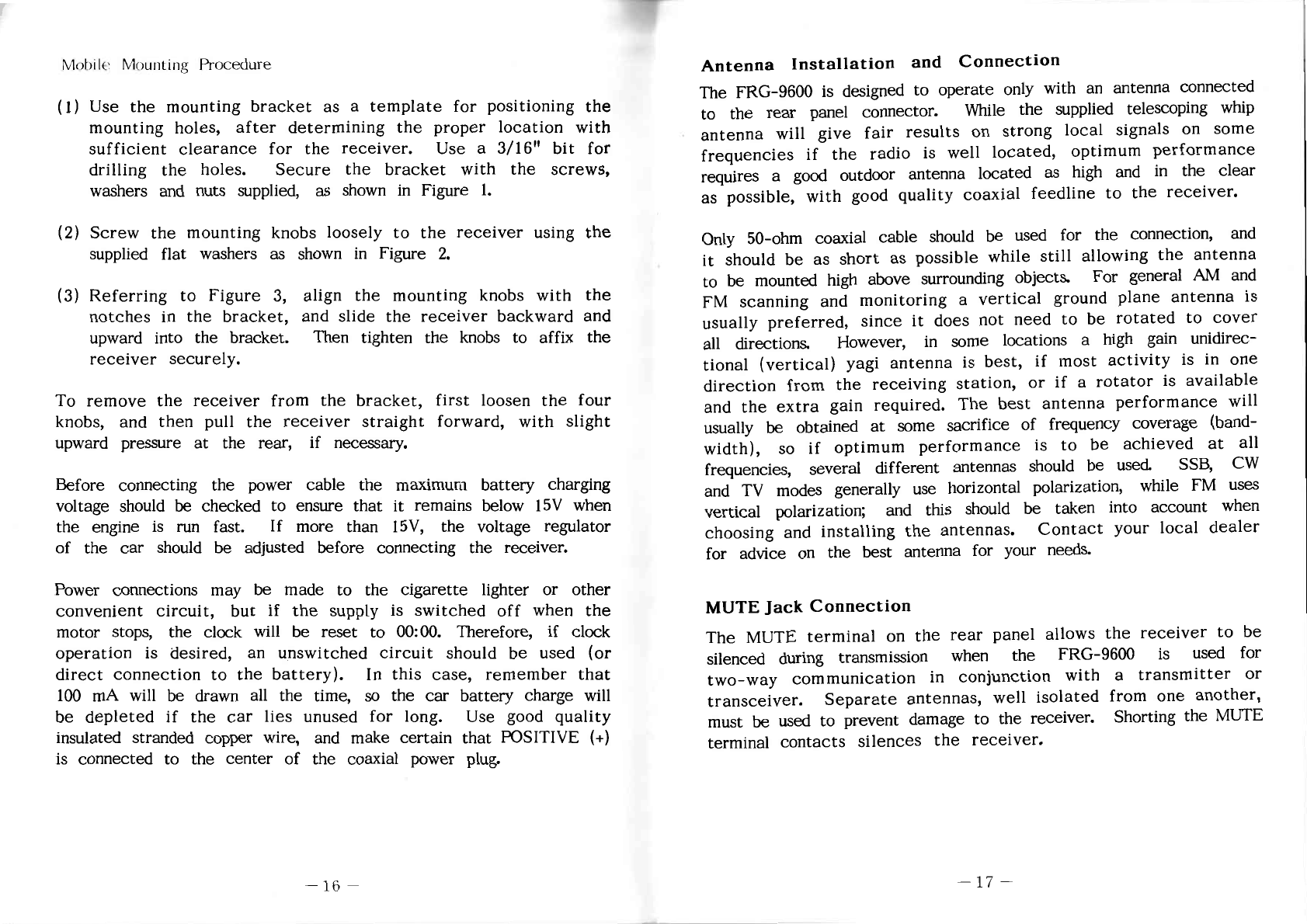
.:53505:
5::
50:53.:
305500
5555:
MES:
5::
w:_::0:w
.53505:
5::
0:
55555
555::
0:
5553
5:
:535
.:5::0:5
5:0
50::
55:50::
:53
.5535
5:5:5:5m
.:53505:5::
:0
5:355:53
5
:33
:0::0:3_:00
:3
:0::50535500
353-03:
:0:
5553
5:
83.03::
5::
:5:3
5355:5553
w:::35
550:555
5:
0:
:53505:
5::
530:5
5:5:
:55:
5::
:0
5355:
MESS:
5:
:.
305053300
:05_.
”PHD—2
.5555:
:30:
:0:
5::5::5
:55:
5::
:0
50355
:0:
5555
3500:
:30:
:05::0U
55555
5::
m:_:5:5:_
5:5
w::500:0
:5:3
530005
0:5
:5:5:
5:
550:5
5:::
5:5
50:53:55:
503:5...
.553
:2:
53:3
32:53:55:
355035:
53
3:55:5w
55505
>:.
5:5
:50
.mwm
.5553
5:
550::
5::5::5
555::5
5:555
5530:5335:
:5
:5
555505
5:
0:
3
50:55:85:
535350
:3
05
.:::5:3
5:53
55550
30535::
:0
5033555
5505
:5
555550
5:
35353
:33
50:55:85:
5::5::5
:55:
5::.
55:33:05:
35
5:5
5::
5:5
535355
5:
55:0:
5
:3
:0
5055::
533505:
5::
50::
:0::0535
5:0
:3
5:
:3355
:505
3
.:55:
5:
5::5::5
55:
250553
35:03:
053553
55
:wE
5
5:03:58:
550:
:3
.5530:
5050535
:5
5.60
0:
55:5:0:
5:
0:
555:
:0:
5505
3
50:35
55:55::
335353
3 5::5::5
5:53:
5:305
:50:::5>
5
w:_:03:05
5:5
w::::505
2r:
5:5
3?.
55:5
:0
r:
5:05.30
55:30:55
5>0:5
:5:
55::305
5:
0:
5::5::5
5::
w:_30:5
:3::
53:3
2:550:
55
::0:5
55
5:
550::
3
5:5
.:0:05::00
5::
:0:
5553
5:
550::
5550
55500
5:0-om
3:0
.:53505:
5::
0:
55555:
55500
5:53:
500m
:33
.5358:
55
55:0
5::
:3
5:5
:mE
55
55502
5::5::5
:005:30
500m
5
55:33:05:
50:55:0::5:
5353::0
.55:500:
:53
5:
0:55:
5::
::
5530:5355:
5505
:0
25:95
:500:
m:0::5
:0
53355:
:5:
53m
:33
5::5::5
:53
53:00:55:
55:53:
5::
55:3
.:0:05::00
5:5:
:55:
5::
0:
55:05::00
5::5::5
:5
:33
:50
555:0
0:
5553555
5:
88.0%:
5::.
305053300
535
3055—553:
5::5::<
53::
:530:
55.500
5::
:0
5::50
5::
0:
55:05::00
5:
Ai
mar—.50.:
:5::
55:50
5:55
5:5
.533
5::00
55553....
55555::
33:53:
500m
553
5:0:
:0:
5553::
55:
:50
5::
3
555555
5:
:3
55:0
3535:
:50
5::
0:
.553:
5::
:5
:35:5
5:
:3
<5
8:
:5::
5:5555:
.5550
3::
::
.3535:
5::
0:
:0::05::00
:0535
:0:
5553
5:
550::
33030
55:03353
:5
553555.
5:
:0::5:5:0
:00:0
::
.5:0:5:5::.
.0060
0:
:555:
5:
:33
:85
5::
.58:
5:05
5::
:5:3
::0
55:03.35
3
35:3:
5::
:3
:3:
.33030
5555500
5:5
:0
5::w:
535530
5::
0:
5555
5:
:55
50505500
530.:
.:53505:
5::
55:05:50
555:
55:53:55
5:
550::
:50
5::
:0
55555:
5530::
5::
.>3
:5::
5:05
::
.:55:
:3:
w:
555:5
5::
:5:3
>3
30:5:
5::5::5:
3
:5::
5.55:5
0:
55:05:0
5:
550::
5m5:_0>
m::w:5:0
3535:
535555
5::
2:50
530:
5::
:5:05::00
555::
5555505:
:3
.:55:
5::
:5
5585::
553:3
::w::
:33
.5535:
5353:
53505:
5::
:3:
:5::
5:5
:30::
:30:
5::
5500:
:53:
.:5:05::
5::
50::
:53505:
5::
5>055:0 :.
4255055
:53505:
5::
:3:
:5
0:
80::
5::
555:
:5:.:.
.:5:05::
5::
0:5
553:3
5:5
5:53:05:
:53505:
5::
55::
5:5
.:5:05::
5::
:_
5:30:
5::
:33
5:0::
w::::305
5::
55:5
.m
5:33.:
0:
w::::5:5m
Am:
.N
5:53:
:3
:30::
55
55:53
:5:
55:53:
5::
553
:53505:
5::
0:
35500:
30::
w::::305
5::
35:0m
AN:
.:
5::5::—
5
:30::
55
.55:::3m
5:3:
5:5
55:53
.5355:
5::
:33
:5:05::
5::
5:305m
55:0:
5::
w::::5
:0:
3:
sm
5
553
.:53505:
5::
:0:
50:5:520
55:03:35
:33
53502
5:05
5::
55:55:55
5::5
.5530:
w::::305
5::
5503350:
:0:
5:53:55:
5
55
:5:05::
m::::305
5::
553
AC
5555095
m:_::30:>_
52:02
Mobile Mounting Procedure
(I)
Use the
mounting
bracket as a template
for
positioning the
mounting
holes,
after
determining
the
proper
location
with
sufficient clearance
for
the
receiver.
Use a
3/16"
bit
for
drilling the
holes.
Secure
the
bracket
with the
screws,
washers
and
nuts
supplied,
as shown
in
Figure
1.
(2)
Screw
the
mounting
knobs
loosely
to
the receiver
using
the
supplied
flat
washers
as shown in
Figure
2.
(3)
Referring to
Figure
3, align the mounting knobs with the
notches
in
the
bracket,
and
slide
the
receiver
backward
and
upward into the
bracket.
Then
tighten
the knobs to affix the
receiver
securely.
To
remove
the
receiver
from
the
bracket,
first
loosen
the four
knobs,
and
then
pull
the
receiver
straight forward,
with
slight
upward
pressure
at the
rear,
if
necessary.
Before
connecting
the
power
cable
the maximum
battery
charging
voltage
should
be
checked
to
ensure
that
it
remains
below 15V
when
the
engine
is run
fast.
If
more
than
15V,
the
voltage
regulator
of
the car
should
be adjusted before connecting the receiver.
Power
connections
may be
made
to the
cigarette
lighter
or
other
convenient
circuit,
but
if
the
supply
is
switched
off
when the
motor
stops,
the
clock
will be
reset
to
00:00.
Therefore,
if
clock
operation
is
desired,
an
unswitched
circuit
should
be
used
(or
direct
connection to the battery).
In
this
case,
remember that
100
mA
will
be drawn
all
the time, so the car battery charge
will
be
depleted
if
the
car
lies unused for
long.
Use good quality
insulated
stranded
copper
wire,
and
make
certain
that
POSITIVE
(+)
is
connected
to the
center
of the
coaxial
power
plug.
Antenna
Installation
and
Connection
The
FRG—9600
is designed to Operate only with
an
antenna connected
to the
rear
panel connector.
While
the supplied telescoping whip
antenna
will
give
fair
results
on strong
local
signals
on
some
frequencies
if
the
radio
is
well
located,
optimum
performance
requires
a good
outdoor
antenna
located
as high and in the
clear
as
possible,
with
good
quality
coaxial
feedline to the
receiver.
Only
50-ohm
coaxial
cable
should
be
used
for the
connection,
and
it
should be as
short
as
possible
while still allowing the
antenna
to be
mounted
high
above
surrounding
objects.
For
general
AM and
FM
scanning
and monitoring a
vertical
ground plane
antenna
is
usually
preferred,
since
it
does
not
need
to be
rotated
to
cover
all
directions.
However,
in
some
locations
a high gain
unidirec—
tional (vertical) yagi antenna
is
best,
if
most activity is
in
one
direction
from the
receiving
station,
or
if
a
rotator
is available
and the
extra
gain
required.
The
best
antenna
performance
will
usually
be
obtained
at
some
sacrifice
of
frequency
coverage
(band-
width),
so
if
optimum
performance is to be
achieved
at
all
frequencies,
several
different
antennas
should be
used.
SSB, CW
and TV
modes
generally
use horizontal
polarization,
while
FM
uses
vertical
polarization;
and
this
should be
taken
into
account
when
choosing
and
installing
the antennas. Contact your local dealer
for
advice
on the
best
antenna
for
your
needs.
MUTE
Jack
Connection
The MUTE
terminal
on the
rear
panel
allows
the
receiver
to be
silenced
during
transmission
when
the FRO-9600 is used
for
two-way
communication
in
conjunction with a
transmitter
or
transceiver.
Separate
antennas,
well
isolated
from one
another,
must
be used to
prevent
damage
to the
receiver.
Shorting
the MUTE
terminal
contacts
silences
the
receiver.
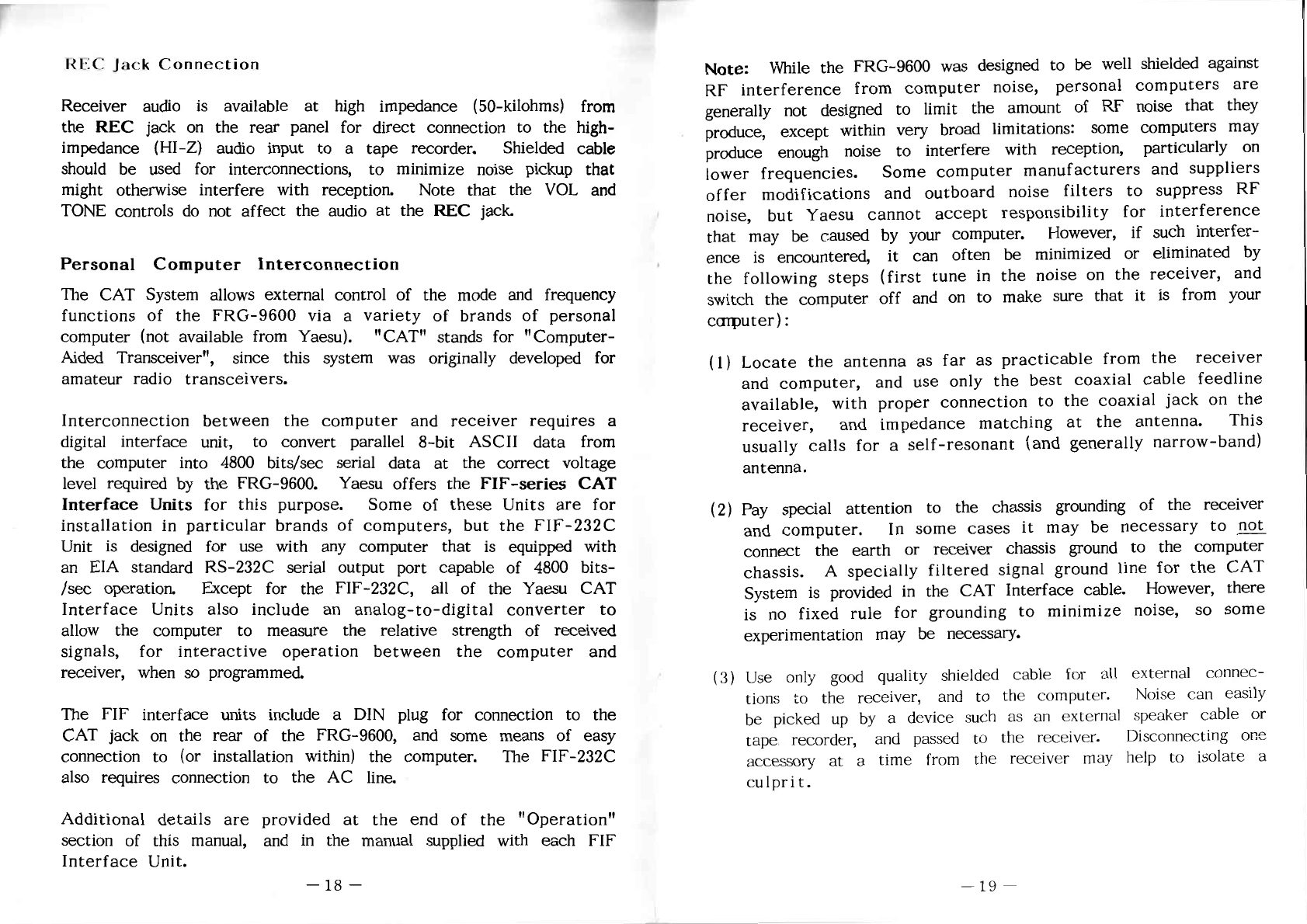
.0000000
0
0000000
00
0000
0000
0030000
000
00000
00000
0
00
000000000
000
90000000005
.0030000
000
00
000000
000
.00000000
.0000
00
00000
0000000
00000000
00
00
0000
00300
0
00
00
000000
00
30000
000
00002
0000000000
000
00
000
h0030000
000
00
00000
-000000
0000000000
:0
000
00000
00000000
000000
000m
300
003
Amy
0000000000
00
00000
00000000000000
00000
00
.0000:
030000000
00
w0000000w
00.0
0000
0000.0
00
00
00000
00000302
.0300
000000000
00000
000
00
0003000
00
0000008
(3000
000
000
00:
00000w
00090
0000000
30000000
<
.0000000
000000000
000
00
008%
0000000
0030000
00
00000
000
0000000
law.
00
000000000
00
0000
00
00000
00000
00
000000000
000
0030000
000
00
w0000000w
0000000
000
00
00000000
0000000
000
03
.0000000
000000060000
3000000w
0000
000000003000
0
000
0000
300000
000k
.0000000
000
00
w00000000
0000000000
000
.0030000
000
00
000.0
0000000
000
00
0000000000
000000
0005
00000030
0000000
00000
0000000
0000
000
300
000
000
000000000
000
0030000
000
00000
00000000000
00
000
00
0000000
000
000000
0:
”000000000
0000
00000
00
00
0000
0000
000E
00
00
000
0.00
000000000
000
000030
000
“0030000
000
00
00000
000
00
0000
0000:
00000
w0050000
000
00
0000000000
00
003000000
00
00000
000
00
00000000000
00
0000
00.00000
0000
0
0000030:
000000000
000%
00
000000
00
0000
0000
00000000000
000
0000000000000
000000
000000
0000
00V
000
.0000:
mm
00000000
00
000000
00000
00000000
000
00000000000000
000.00
00000000
000
00000000000000
000000000
0000m
00000000000
0030.
00
3000000000
.000000000
0005
000000000
00
00000
0w0000
0000000
0000
0000000000
00000
"0000000000
00000
30>
000003
0000000
.0000000
0000
0000
00000
“E
00
0000000
000
0000
00
0009000
000
3000000m
000
0000000000
00000000
.0000:
00009000
00000
000000000000
00m
005000
0020000
:03
00
8
00000000
003
800-000
000
0:03
H0002
.0003
000000000
0:.”—
0000
0005
0000000
0000000
000
00
000
0000000
0000
.00
0000000
..00000000O=
000
00
000
000
00
000000000
000
000000
00000000040
.000
U<
000
00
0000000000
000000000
000
Ummmunzm
00%
000000000
000
0000005
0000000000
000
00
0000000000
0000
.00
000000
00000
000
.ooomLUw—L
000
.00
0000
000
00
000..
00000
000
00
0000000000
00.0
m000
25
0
0000000
0000
000000000
000
000.
00000000w000
00
00005
.0030000
000
000000000
000
00005000
000000000
0300000000
000
000090
0030000
.00
00m00000
0300000
000
00000000
00
000000000
000
3000
00
00000>000 00300000002000
00
0000000
0000
00003
000000000
0.40
0000
Mr
000
.00
:0
.Ummmanzm
000
0000
0000a
000000000
000\
-0000
oowv
00
0000000
0000
000000
000000
Ummmuwm
00000000
«am
00
0005
000000000
00
0000
000000000
000
0005
000
000
0009000
00
0003
Ummmunzm
000
000
6000000000
00
000000
0000000000
00
00000000000
000
000
00003
00000
00
008w
.0000000
0000
00.0
00003
00000000—
.—.<U
000.000.0000
000
000.000
0000
w
.oowmIOm—m
000
00
00000000
000000
0w0000>
0000000
000
00
0000
000000
0000000
0000
0000
000000000
000
00000
0000
:Um<
000
0000000
0000000
00
.0000
00000000
000090
0
00000000
0030000
000
000000000
000
0003000
00000000000005
00030000000
00000
00000000
000
0000000000
300000000
003
0000000
0000
00000
3100300000;
0000000
000000000:
00.0
000000
=0L<U=
0000000
0000.0
000000000
0000
0000000000
00000000
.00
000000
00
00000000
0
00>
0000-000
000
.00
000000000
000000000
000
00000
000
00
_000000
00000000
03000
000000w
0000
000k
COmHUOGEOUhOHn—H
MOHH—QEOU
=w—h0mh0n—
0000.0
Um.”—
000
00
00000
000
0000.00
000
00
00000000
mZOH
000
00>
000
0000
0002
.000000000
0003
000000000
000500000
009E
0000
000000
00000
0000000000
00
0000000080005
000
0000
00
000000
00000
0000000m
.00000000
0000
0
00
00000
00000
ANIEV
000000000
.030
000
00
0000000000
00000
00.0
00000
0000
000
00
0000..
0mm
000
E00
0000000063
0000000000
00000
00
000000000
00
0.0000
00300000
003000000
0.00%
Umm
b
REC
Jack
Connection
Receiver
audio
is
available
at
high
impedance
(SO-kilohms)
from
the REC
jack
on
the
rear
panel
for
direct
connection to the high-
impedance
(
HI
—Z)
audio input to a tape recorder. Shielded cable
should be used for
interconnections,
to minimize
noise
pickup
that
might
otherwise interfere
with
reception. Note that the
VOL
and
TONE
controls
do not
affect
the
audio
at the
REC
jack.
Personal
Computer
Interconnection
The
CAT
System
allows
external
control
of the
mode
and
frequency
functions
of the
FRO-9600
via a
variety
of
brands
of
personal
computer
(not
available
from
Yaesu). "CAT" stands
for
"Computer-
Aided Transceiver", since this system was originally developed
for
amateur
radio
transceivers.
Interconnection
between
the
computer
and
receiver
requires
a
digital interface unit, to convert parallel
8—bit
ASCII
data
from
the computer
into
4800
bits/sec serial data at the
correct
voltage
level
required
by the
FRO-9600.
Yaesu
offers the
FIF—series
CAT
Interface
Units
for this
purpose.
Some
of
these
Units
are
for
installation
in
particular
brands
of
computers,
but the
FIF—232C
Unit is
designed
for use with any
computer
that
is
equipped
with
an EIA
standard
RS-232C
serial
output
port
capable
of
4800
bits-
/sec
operation. Except
for
the
FIF—232C,
all
of
the Yaesu CAT
Interface
Units
also
include
an
analog-to-digital
conVerter
to
allow the
computer
to
measure
the
relative
strength
of
received
signals,
for
interactive
operation
between
the
computer
and
receiver, when so programmed.
The FIF
interface
units
include
a
DIN
plug for
connection
to the
CAT jack on the
rear
of
the
FRO—9600,
and some means
of
easy
connection to
(or
installation
within)
the computer. The FIF-232C
also
requires
connection
to the AC
line.
Additional details are provided
at
the end
of
the "Operation"
section
of this manual, and in the manual
supplied
with
each
FIF
Interface
Unit.
Note:
While
the
FRG-9600
was
designed
to be
well
shielded
against
RF
interference
from
computer
noise,
personal
computers
are
generally
not
designed
to limit the amount of RF
noise
that
they
produce,
except
within
very
broad
limitations:
some
computers
may
produce
enough
noise
to
interfere
with
reception,
particularly
on
lower
frequencies.
Some
computer
manufacturers and
suppliers
offer modifications and outboard
noise
filters to
suppress
RF
noise,
but
Yaesu
cannot
accept
responsibility
for
interference
that may be
caused
by
your
computer.
However,
if
such
interfer—
ence
is
encountered,
it
can
often
be
minimized
or
eliminated
by
the following
steps
(first
tune
in
the
noise
on the
receiver,
and
switch
the
computer
off
and on to make
sure
that
it is from
your
ccnputer) :
(1)
Locate
the
antenna
as
far
as
practicable
from the
receiver
and
computer,
and
use
only the
best
coaxial
cable
feedline
available,
with
proper
connection
to the
coaxial
jack on the
receiver,
and
impedance
matching
at the
antenna.
This
usually
calls
for a
self-resonant
(and
generally
narrow-band)
antenna.
(2)
Pay
special
attention
to the
chassis
grounding of the
receiver
and
computer.
In
some
cases
it
may be
necessary
to
not;
connect
the
earth
or
receiver
chassis
ground
to the
computer
chassis.
A
specially
filtered signal ground line for the
CAT
System
is
provided
in
the
CAT
Interface
cable.
However,
there
is no fixed rule for
grounding
to minimize
noise,
so
some
experimentation
may be
necessary.
(3)
Use
only
good quality shielded
cable
for
all
external
connec-
tions to the
receiver,
and
to the computer. Noise can easily
be picked
up
by a
device
such as
an
external Speaker
cable
or
tape.
recorder,
and
passed to the
receiver.
Disconnecting one
accessory
at a time
from
the
receiver
may help to
isolate
a
culprit.

:0000
000
00
00:00
0000
000
00:02
000
:0
000
0w00:
mE>0000:
000
00
0m00
0:0>
000
00
00000000
00:00
000
E
0000000000:
00000000
:03
:000000
000
.000000000
0000
E
“0000
0002
000000
000
0030
0000000000:
000
:0000
0:00:00000000
mE00000
00:000:
:05
:
n:000000
000
0w0w000_0
00
00000:0
00:
0:
000000
03
:0
Z>>OQ
000
0.
.0_:00_0
0000000
000
0_
0:00
00
0000
E00:
:0
0000000
03\Z>>OQ
000
000
0000
:00
000
000
a00m0m00000
00
:03
:000000
000
000000
03
:0
Z>>OQ
000
000:0
E0w0
000
00
.009:
00
0000
000:0
00:0
0000
0000
:05
000000
000
.000000
000
:000000
000
000>>
000000
:03
0000
00
0000000
50?:
:0
:030:
0x0:
000
00
00000
0000
000
.00000000
0:000>
:0>0
0000
:05
:000000
000
00000010
:00
0:
0000
000
000000
03
:0
Z>>OQ
000
000:0
0000000
000
0003000
0:.
.0000000 0: 00:0: 000 0:000; 0:000
000
00
000..
000300000
00:0:00
000
0:00
0:0000:w
0:0
A0000
0:
0000:
0000
0:000:
0000000
:0000
0
00
0000
Amy
.00
030000800
0000
0:00
35:00
000
000
00:00
.:0>_:0:50:00
:00:0
0
mE03
A:
”00:000.:0
000
0: 00000
:00:
000 00
00:0000
M0002
0<
000
0
0000
00
000
00000000w0000000
000
,000>:00::00_<
.000E
3-020
000 E
NI0
000
00 000000
:03
00000
mE000‘
.000000
00
“0000000
0:0:00000
0
00
0000
00
0000
00
:00
A0000
000
0000000
0000000
n5\Z>000
000
:0
00:0
w00000
E08
000
:000fl
000000
00
00:0000
MZOF
000
0:0
.0::0_0>
00000800000
:00
60000
00>
000
000.0000
000000000
00:0000 000 :0
900000:
00
Bo:
:05
0000-00:
000
0:0
0800000
:05
00000::
E
0:00
mE0000
000
n0000000:
0000
:05
00w00
mE000:
000
0000000
000
00000
000.0
000000
0<0Q
000
000:0
00:02
000
30000
0:
0:00
000000000
0003
0000000
000
:0
03000
00
00000000
000000
000
000.0:
.:0>0
0:000
0:0
0:000
:000
:0000
00
000
H00
0000
000
000:0
000.0
.0000
000:0
m00:>0
000
000:0
0:00:000000
000
00
00000000
00 0005
000
00000000
000
:0000
00:0
000:
000
I
00000:
0:
0000:
00:0000
00
00
0:
0
0000
m0000000E
.0000
:05
00m:
000
00
0090
0x00
000
00:0000
00
0090
0
0:00
000m.
.m
d
.m
.o
000:0
.NIE
060
00
0:
0000000
000
00
6000:0000
:00
.000:
:9.E
000
00
0:000000:
00
:05
00
~32
000
30000
00
00000000
000
0
0000
0002
03-020
:0
00000
:0000
00:00:00
0000
00000000
000030000
000::
0000
:000:0000:
000
.NIE
me:
000
mm
00000000
00
:05
0000
000003
0000000
w000000000:0
SE
0000:
0
00
00000000
000
:0000
00
0000
0000:0000:
00:03
000
003
0000000
000::
000::00
000
:00
mE0000>>
0003
000000
MQOZ
000
0000000
00000000
.000
00
000000000
000
0>000
000000000
300
0:
:000:000:
0000
00::0>
000
.0000
00000
000E
000
00
00m?
000
00
000.:
000000
MOOE
000
000:0
000000000
A0000
00000:00000
E000
00
000
0:0
A0000
E00:
000
00
0000
000
000
00000050
Z<Um
0<
000
0.500
00%
000
0000
0:00
0002
.02000:
00
00000000
000
000
.00000
0000000
000
0000
00000000
00
00::00
:0
00:00:00
000::
000
0:0:000m
00
00
000:0
h00::
0000:0000
0:
000::
20
00:3
00%
000::
31.20
000
I
0030000”—
00000000m
SE
.00
0:0
on
00000
:0
0:00000:0
0000:
=0000000
0:00:03?
000
000
“00:0
000
00
00:00:00:
000
000::
0000008:
0000
:0
:0000
00
00:3
000
00
000000000
00
:05
C00
00000050
0000
00:5
0000:
000
0:303
0000
0000
000000
000
000E
00000000:
000
6003:0000
0000000:
000
00
0000::
000
00
30/009.
000
02
00
0m
0080
1:0
0..
.080:
.2020:
90
5
.0020
3.80.00:
3000
:05
0000000
000
.00000:>0:0
0000
0000
00:
000
00
00
.0000:
000
:0
0:00
00
000010000
000
(00
000
080000
00>
000
000000
.0000000
m000000:0
000
0:
0000:0000
00
.00000::00
0000:
0000
0.000
00000000000
0000000
000
:0300
000
0000
0:00
w000000
:0000
E02000:
000
:0
00000000
0000
000
w000:0
0:03
0:000:00
00:00:00
0000000
0000
000:
000000
.0:0:m:000
000
00
00000000
00:00:000
000
0003
:000:000
00:
00
:000:000
000
.0:
00:00
00
000000000
00
:00
0:200:00
000%:0
00000>00
000
0.0
0E00
00:00:50:
.000000
000000
00
0000-000
000
00
00:00:000
000000
000000
20:.ém—n—O
mammmm
i?
§§§§§§
OPERATION
§§§§§§
Basic operation of the
FRO—9600
is quite simple.
However,
some
of
the
advanced
digital functions can be confusing at
first
if
the
operator
is
not
familiar
with
the operation
intended
by
the
designers.
Please
read this
section
through carefully
while
trying out
each
function on the
receiver,
after
making
sure
that
the
power
and antenna connections have
been
made
correctly,
as
described
in
the
preceding
section.
Rotate
the
VOL
control out of the
click—stop
to turn
on
the radio.
If
it
has not been
used
previously, the display
will
show
"60.000.0"
(MHz),
in
the
"FM—N"
mode,
"5 kHz"
steps
at the left
and
"DIAL"
to
the
right
of
the
frequency.
Otherwise,
the
frequency, mode
and
status last
used
(before the radio was last
switched
off)
will
be displayed.
If
you wish to
clear
all
data
(frequency, mode
and
memories)
at
any
time,
see
the "Memory
Backup" reset procedure
on
pages
39
and
40.
FM
Broadcast
Reception
—
the
FM—W
mode
The wide
FM
mode
is
described
first,
since
it
is generally the
most
universal
in
terms
of
frequency band
and
channel
steps,
and
the simplest to
receive.
Make
sure
that the
gray
ATT and AF SCAN
switches
(to
the
left
of
the
main
knob)
are set to their
undepressed
(out)
positions. Press
the
MODE
button
(just
to
the
right
of
the
main
knob)
once,
and
verify
that
"FM—W”
is
now
displayed
above
the frequency.
If
not, continue
pressing
the MODE
button while watching for the
correct
mode
display.
Use the
white
numerical keys to
enter
the
frequency
of a
local
FM
broadcasting
station
(usually this will be
between
88 and 108 MHz,
but
remember
that
most
television
stations
also
transmit
their
audio
on
FM—W).
Note that
if
the frequency is below 100
MHz
it
will
be
necessary
to key
in
"0" first.
For
example,
if
the
station
is at 90.5 MHz,
press
0, 9, 0, 5.
Each
time
a
digit
is
entered
the
next
digit to the right
will
blink,
indicating
that
it
is
to be
entered
next
(if
needed
—
you need
only
enter the
digits
you wish to change).
If
you accidentally
press
the wrong
digit
key, just
press
the blue CE key to
clear
your entry
and
start over.
Once
the
desired
frequency is shown on the display
(with
leading
zero
if
below
100
MHz),
press
the
DIAL
button
just
below
the
diSplay.
The
flashing
digit
will
stop flashing, the leading zero
(if
present)
will
disappear,
and
the
FRO—9600
will
now be
receiving
on the
entered
frequency. Adjust the
VOL
control
for
comfortable
volume,
and the
TONE
control
as
desired.
Either
the
main
tuning
knob
or
the
DOWN/UP
buttons (above
the
knob)
can be
used
to
tune
to a different station,
if
desired.
Tuning
steps
will
always be 100
kHz
in
the
FM—W
mode.
Alternatively, the scanning function can be used
if
the AF MUTE
control
on
the
rear
panel is set properly:
(1)
Using
a
small
screwdriver,
first
set
the
control
fully
counterclockwise.
(2)
Tune to a
clear
channel (where
only
noise is heard),
and
gradually
turn
the control clockwise
just
to
the
point
where
the noise
is
silenced.
To
activate
the
scanner
press
the DOWN or UP button and hold
it
for
é—second.
The scanner
will
skip over vacant channels,
and
stop
close
to
the next lower or higher station
(a
beep
will
sound). When the
scanner
has paused, the
digits
will
each
blink
once
from left to right.
If
you again
press
the DOWN or UP button
the
scanner
will
be disengaged,
and
you
can
then
use
the
DOWN/UP
buttons or main knob to tune
in
the station
clearly.
If
the DOWN or UP button is not
pressed
to disengage the scanner,
it
will
resume scanning automatically after
the
rightmost digit
has
blinked.
Note
that,
in
this condition, the
scanner
will
continue indefinitely
in
the same direction to the very edge
of
the
receiving range
(60
or 905
MHz),
and
then
jump
to
the other
003
00:3
.:0:01:
.00::0:0
0:
:000000
0::
00:?
00:00:00
0:
:0::
3:00:05
0::
w::0:0::00
000::
0::
3:00
:0>00
=05
m0:0:000
00:30
0:
00::0E00:
:0
:02:
000
00::
0:08
00:33
.0000
0:::
0:
200::
3:0..000:
0::
:000
0:
000000-
0
:0:
30:
n5
:0
2309
0::
0:0:
0:0
000::
#2
0:0
0::m:0
3:0E0E
0::
w0:000:n:
3:
3:00:00:
6300000:
:0::000
:000:
:0
.A2ID
000
0::w:0
3:00:00:
0::
000:0
:05
0::
80::
3:0E00:
:0::
0:
0:00
0:0:00:
:0:::0
0:
3:000000:
0:
:03
::
00
.00:00:0
0:
:05
3:00:05
0::
0:0
:05
0::
0:
::::0
2:?
0030:000
.340
2
000:0
.3:000:>0:0
:02:
:0:00:::00
0
0:
00:0:0
02:00:00:
0>00:0:
0:
:00?
003
00:3
002000:
0:
:05
0000805
:0
:02:
00:00:00
0::
3:00
.0:0:0
3:00:02
0::
0:
0000
0:0
030:
n:D\Z3OQ
0::
00:3
.0:0:0
3:00:02
0::
0:
0000
0:
:00:
m0:00:
0::
:0::»
002000:
0:
:05
30::
.3:000:>0:0
00:0:0
000:
0:0:
02:00:00:
:0::0
300
::
.0:0:00:0
:0::0
0::
:000:
0:
030::
.5\Z3OQ
0::
000:0
:0
.000:
w::00:
0::
0:0:0:
302
.3000
903
00:00
:0
00:0:0
:00:
0>0:
:03:
0:
0030:
60005
3.5800:
0::
00:000
:0:
m2
w::000:0
0:0:0:
00030:
0::
00
0::w:0
:0::0:0
3:082:
0::
:0::0
:00:
00:30
000
:00:
0::
:0::
:0::0
3:00:00:
0
:000:
0:.
002000:
0:
0:00?
3.2“:
.022
2:0:
.0008
000
30:00:00:
:0::000
0:
00030:
000:
00:
:0:0
0::
::
00>m:
0:00:00
:0::
IO:
:0::
00302
.0:0:0
3:0E02
0::
:0::0
0:
30:
m2
0::
000::
:00_
.00:0:0
:00:
200005
0::
:000:
0 :.
.0:0::
:0:0:
0
:0
00::0500:
000::
:0
w0:00000
000
w0:000:0
:0::0:0
:00:00>000
30:0
:05
000::
00:00
0::
0:
:0
0:0
30::
:0::
:00:
0::
:0:
.0000
:00:
0>0:
:0.3
00
:00_
0:000
So
I
oo:
0.00
00.0
:0
.06:
.060
0::.
...
.8:
0::
0:
:0
0:0
58:0
:0:
I
09
0:0000:0
3:082:
0::
:0::
0:02
.0:0:0
:05
0::
0:
0:
::::0
2:3
:0>:000:
0::
00:0:0::
00:3
.vm
0:0
mm
0:0000:0
:0:
:::0:
00
0:0
.mm
:0::0:0
0:0:0
0:
030:
0::
000::
000
.3000000::
:000
0::
0:
:20
0::
000:0:
:0::.
.2IQ
0:0
..:..
...m..
000:0
000
.022
0.3
0:
:0:0
0::
000:0:
0:02
.300:
50::
0::
:0
00:0
::w::
:030:
30:
2IQ
0::
3:3
3:0:0:00EE:
00326:
.030:
:0:::3:
=9.
0:0
=9.
0::
000:0
:0::.
.0>0:0
000::0000
000::00:
w:::0:
0::
:0
300
m::00
022
:60
:0
00::0:0
0::
0:
000:
.0:0:0
:05
0::
0:
.:0::r.:
.0:
:w00:::
om
0:0000:0
3:00:00:
0:
0:0::
0:30
o:
:0::
so:
:0:::
:0...
0:2
0.3:
0:0
02
.00:
.000
.30
:0
0:0
0:0::0:0
w0::000000::
2
n:
0:::0>0:
:003
080000
.0000:
3-2.:
0::
0:
”0:00:03:
0w0:0:m
3:00:02
.0:0:0
:05
0::
0:
05080:
0033008
:0::0:0
3:909:
:0::
0:0:
000::
000
3000000:
:05
0::
0:30
0:
21¢
00::
0:0
.0::w:0
:0:E00
00:05
3:03:08
03:
0::
000:0
:00_
.0:0:0
:05
0::
0:
00::000
00
0:
0000:
000:
00:
:0::0:0
0
00:3
.0:0N
w0:000:
0::
:0::0
0:
:0:::0E0:
.mo
:m00:::
oo
0:00:0:0
3:089:
0:
m0:30v:
00:3
.30
.:0::0:0
0009000
m:
l
O:
.0003
000
0000500
mo
I
oo
0:0:00:0
00
.002:
000
0:
::w:0
0.00:
00:00
0::
3:3
0:0::0:0
:0
002w
:000
.0000300
m0::0000
:0
n:
00030:
0::
00
:0:::0:
00:05
3880::
0
w0::0:00
00:3
0000
0:
:000:
0::m:0
03
000:0
.:.0:0
.2
.0:
.mo
.No
.3
.oo
:0:
:0::0:0
0
0:::0000
0:
0000
03030
0:0
0::w:0
0.5:
:0::
0:02
.8
0:
oo
08::
00:00::0:
0:0
0:00:0:0
38:00::
00:
0::.
.0:0000:0
3:00:08
:0:
:0
00:00::
0:
0:
:00030:
n5\Z3OQ
0::
:03:
m0::00:0
:0::0:0
000
m::00000
.0:0:0
3:00:02
0::
0:
.30:00:0
30:00:00:
0::
:0
::w::
0::
0:
:0:::0:
:0::0:0
3:00:08
0::
000
:30:
:0
0000000:
0::
3:
00:00:00:
0:
0:0:0
3:00:02
0::
0: :0::0:000
.0:0:0
:05:
0::
::0::
00:0:0
3:000:>0:0
000::
000
30:00:00:
300
:0
:000:
:00:00:
0::E:00
.000:
:0::0
0::
00
.0:0:0
3:00:02
0::.
.:0>:000:
0::
:0
0w00:
0::
0:33
0:0:3300
00:::00
00030:
:0
w::::000
60:00:
:0::
00:0:::00:00
3:3
.0:0:0
.0500:
000
000::
.3000000::
:0
02:00:00
030:0
.30:00:0
0::
00 30:00:00:
0::
:0
::0:
0::
0:
:00:
030:0
..1:<:Q..
3:
00:00:00:
000
0.500
00:00000:0
0::
0:
0000
.0:0:0
:05
0::.
.3:0>::00000:
.030:
2:000”:
3:902):
2
0:0
100:5
0::
3:
00:00:00
.3:0_.002
:0
:05
:0:::0
.00::0:000
:0
..00:0:0..
03:
00:
003-0%“:
0::.
w0m0000m
3:00:02
000
2000::
.0w0000m
3:00:02
.0m00:
0:0::00
0
0:::05
:0::000
0::
000:
0:
.:0:0:
0000::000:
.00::0:000 000::
00:00:
003
.w0::0000
000:: 000
0w00
rl|||lr||1
edge
and
keep
scanning.
Use Limited Band
Operation,
mentioned
later,
to
keep
the
scanner
within a
certain
range.
Memory
Storage,
Recall
and
Memory
Scanning
The
FRO—9600
has two
"states"
of
operation, either Dial or Memory,
selected
by
the
DIAL
and
MR
(Memory
Recall) keys, respectively.
The Dial
state,
used
in
the
procedures
above
and
indicated
by
"DIAL" shown just to the
left
of
the frequency
on
the display,
allows
selection
of
frequency, mode and tuning
steps,
with
unrestricted
knob tuning, scanning or keypad
entries
anywhere
within the
range
of the
receiver.
The
Memory
state,
on the
other
hand,
permits
instant
recall
of any
frequency
and
mode
previously
stored
from the Dial
state.
Operation
in
the Memory
state
is
indicated
by
the presence
of
"CH"
and
the
memory
channel
number
to
the
right
of the
frequency
display.
In
the Memory
state,
scanning
and channel stepping
(with
the
DOWN/
UP buttons) is
in
blocks
of
ten
memory
channels.
The 100
memory
channels
are
numbered
from 00 to 99.
Note
that
two
digits are always
used
to
describe
a channel (ie., 00,
01,
02,
09,
10, 11,
etc.),
since
two
digits
must be used when entering a
memory
channel
number
on the
keypad.
For
scanning
purposes,
each
group
of
channels
with
the same ten's
digit
is one block, so
channels
00
—
09
compose
one
block,
10
—
19
compose
another,
etc.
When
keying
in
memory
channels
00
through
09,
remember
to
enter
the leading
zero.
When a station has
been
tuned
in
as
desired
in
the Dial
state,
just
press
the
two
memory
channel
number
digits,
and
then
D—M
to
store
the Dial frequency and mode into that memory channel
(Operation remains
in
the Dial state).
Memory
Storage
Example:
In
the
FM—W
mode,
assume
your
favorite
FM
broadcasting
stations
are
at
90.1,
95.6,
101.5, 103 and
104.5
MHz, and
that
you wish to
store
them
in
memory
channels
90
through
94.
First,
in
the Dial
state,
tune
in
the station at 90.1
MHz
using any
of
the tuning
methods described above. Then press the "9"
and
"0"
(white)
keys,
followed immediately with the
D—M
key (lower right side
of
the
main
knob).
Next retune the dial to 95.6
MHz,
and press "9", "1"
and
D—M.
Then
retune
the dial to the
next
frequency,
and
press
the keys to
store
channel
92, and so forth for
channels
93 and 94.
When finished the
receiver
will
still be
in
the Dial
state.
Note
that the memory channels
(90
—
94)
chosen are
all
in
the
"90's".
The
80's,
40's,
or
even
00's
(00
—
09)
could just as well
have
been
used,
but the
fact
that they
are
all in the
same
block
will
allow
convenient
channel
stepping
and
scanning
of
these
memories
at a
later
time.
To
recall
the
channels
just
stored,
just
press
the MR key to
enter
the Memory
state.
Notice that
"CI-I
94" appears. Even
if
the dial
had
been
retuned
to
another
frequency
and
mode,
104.5 MHz,
FM—W
would be
recalled.
To
recall
a memory
other
than the last
one
stored,
just
enter
the
memory
channel
digits
on the
keypad
before
pressing
MR
(of
course
the
memory
channel
keyed
in
must
have
been
stored at some time past).
Now
rotate the
tuning
knob,
or press the
DOWN/UP
keys to recall
the
other
channels.
If
any
other
memories
have
been
stored
previously,
they
will
be
recalled
when the tuning knob is used
in
the Memory
state.
When
the
DOWN/
UP
keys are used
in
the Memory
state,
only the
selected
block of
memories
will be
recalled.
When
you want to
remove
memories
stored
in
a particular
block
previously,
press
M
CLEAR.
Operation
will shift to the Dial and
the
memory
will be
cleared,
so
it
will
be
necessary
to
either
restore data to that
memory
(from
the
Dial,
press the memory
digits and
D—M),
or recall another (occupied) memory by pressing
the
memory
digits
and MR.
Press
and hold the DOWN or UP key for %
-second
to
scan
the
memory
block.
In
this
case,
when
more
than
one
block
of
memories
is
stored,
scanning
will
cover
only the block
containing
the
memory
that is
selected
when the
scanner
is
started.
Later,
when you

.0030:0008:0:::
0:
20:30
0w:0::0
:0
00:000
:03:0:00
:0::0
000
.000:0
::m::
0::
:00:00
0:
:0::0:
09$
0::
000:0
:00:
0000
0:::
0:
.0::00:0
0:
0:0:
0:
0330008:
m0:0:
80300
0800
0:
::000:
:::3
000:0
020:
m
0:
w0:00:
.00:0
:000
0:
0000
0:0
000:0
02:
0.0:
::
.00008
:0::0
0::
:00:0
0:
:0::0:
m002
0::
w::000:0
0::
.00:000000
0:
0:::
::
2-2::
0:
000000
00::0:0:0
:0
0:03:00
000000
008
00008
:0::0
0:
0:0:w:0
.00:<
.0:0
0:000
0::
0:3
:00>0:
:::3
:m0000
w00:
00:00:00:
0::
0:
:0::08:
:00:
.00::0
.:0000:0
0:
00:0>
00
00:3
:00
0:00:
0:
008
w::00::
::w::0
0:
:0:0000
0::
0000
008
:0::3
03:30:00
053
00880088
:0
08000::
0005.
.0000
0:0
0:0:0000:
:0:::00-:00:0:00
.00:::0000
0800
0:
.:00w:0
0
0:::
000
:300
000:
0::
00080
0000
0:
0000:
n5\2>>00
:0
:0::
w0::0:
0::
003
00::0:0
:0m
0:
000::00:0m
:0:0:0w
00
0:00
:0008
0:0
00:0:0000::
0>0:0
0::.
.000:
0::
:0:03
0:
003
8080800
:000:
0::
0:::0000
:::3
0030:000
000::
00:83
:0
003000
0:
0.
:00:
0::
0::>::00
:::3
000320
0:
008
0:0::8
0:0
:0
:0000>
0:
:0::
0000000:
0
00
0300:0000
08000::0:08:00
:00
00
0:0::0:0
:0::
0:
w0::000000::
80::
88:00
0:0
000300808800
00303:
:0::
0:02
.0:0000000
0:
008
w0::0:000
0800
00
.:0::000
0:
0::0000
0:0
80::
0:00:3
0:0>
0:8:
:0::
00
:03
00
.0000:
000::
:0
0::>300
:0
00.000
0:0
08:00
0::.
.022
000
0>0:0
0::0000
.2
r:
30::00
0000
00:0
0:0:00:0:
00:02
08:08
000
000800:
8808800
00:00
:0:
022
«:0
l
000
:0
.00:
I
0m:
.00
I
8
:0
M80880
:0:
022
00:.
I
000
:0
000
l
000
:0
.022
man
I
«mm
.022
00:
:0
00:
l
00:
H000300808800
2 r:
0030
0>0:
0:
030::
0m00:
0000000:
0
0:
0:0:
302
.:0:0:
00:03:08
00
.000:0
020:
m
0::
m::00
003080830000
0:
:00
00::
:00
000
0000
:0:3»
0:
03000000
0:
008
02:08:88
0:::
00000
0800
0:
:0:
.0000:
0800
:0
0000
0:0
000:0
:0:3
000
::0:
0:
030
0:
008
:0:000
0000
W
:00»
02:00:00:
00:0
00:0
00:00:00
0::
:0:
00:00:0
0::
:0
00:0
::m::
0::
:0::083
223
:0000000::
0000:00:0
0::
30:0:
:00:
:0::0:
n:m:r:.m
0::
000:0
”000:0
:02:
0:
02880
0::
000
.:0:::08
0:
:0:3
000
:0::
0:0:
:0:00:::00
0
0:
0000
0:0
:0::
000:0
00005
0::
300:
000
00080
.30:
:0
::
.00:::00
080:0
w::::00
02:
mm
0::
00
.0000
0:0
20:00:»:
:0
020:
mm:
000:0
:00:3
022
com
0>0:<
.0:0:300:0
:08800
0:08
000:0
02:
O:
:0
m
:::3
00080.
0:
:08800
0:0
000:0
020:
mm
000
00:
.:0::0:0
0:
00:0
000
80::
:00:0:::0
:0::0
0:0
.022
08
30:0:
00800000:
:0
0::0:00000
.:000:0
w:::0::
m::0000
:0::0:0
.:0>0302
.0303
0::
:0
0038000
:008
0:
020
0:0
02>
:0
000300808800:00:080
0:0
00:08
.000800:
00303:
:0:
0008
0000
0808800
:008
0::
30:
0:
2r:
30::02
003000:
0:
0:
08:90
w0:30::0
:30
223
00:00:00:
m0:>:000:
0::
:0
:0000:0
0:
:00m:0
0:
:0:3
0:00:
0:
083050
0:003
:0::
00:0:
0::0::0:800:0
0308820
003
0:::
0:
:0::000
:0m
0::
:0
m:3:00
0::.
.:0:00m:0
:003
0:
0033:0000
00000:
:::3
:0:::0:
::
w::::0::
00000::0
0:
00:0:
0::
0:0:3
:::00
0::
0:
:00:
00:30:80
:0::000
:0m
0::
0:0:
302
.::00w:0
:0:
00:0:
0::
:0
080:0>
05038800
:0:
:0::000
:0>
0::
000000
:0::
000
.00:30:00:0
-:0::000
0::0:
:0::000
:0m
0::
0:0:02
0:03:000
00000:000:0
::0::
0:
0:0
00:0:030
2<Um
:0::
0:0
00?:
00%
0::
:0::
0:00
0:02
.0:0:0
0:00:02
0::
0:
00008
0w:0:0
0:
033000
:0:
0:
::
0:00
:05
0::
0:
00:3
0083
0>::
:0::0:
m002
0::
000:0
.3805
2-2
1.:
0:
3-2::
80::
0000::
0w:0:0
0.:.
0008
2:2."—
0::
I
93:03:02
0008030080000
0027030.
:0::0:
::0:0-0:-0:0802:
0l2
0::
000:0
”:0::0w::0
0:0808
0::
0m:0:0
:0:
0000002:
0:0808
0::
0:00:0
0:0:
0:
000:
:0:
0:0808
0::
00
0008
:0
000:
0800
0::
0:
000::000
0:
:003
000
:0:3
00::08
000000
0::
000
:0::0:
.:<:0
0::
000:0
:00:
200:-
:08800:
0::
0:
w80w
0:0:0:
w::00
0:03
000
:0>0:0:3
08000:
0:
:003
000
:0:3
:0:000
0:
00::08
:0:::
0::.
0:0808
00:00:00
0::
:0
:0::
:::3
0:00
:05
0:0
0::
w:::::3:0>0
:0::0
0::
000
.:00000:0
003
m2
0:0:0:
:00:
:05
0::
0:
0000
:00:
000::
0:
:00:
00:00:00:
0:0
0008
w0:>:000:
0::
w0:::::0
000
”0:00
0:0802
0::
80::
0:0:0
:80
0::
0:
0:0:0:
0:
0003
2:380
03:
0:0
0:0:.:.
20:00::
:0
0>::00000::::
0030808
00:00000
0::
:0
0:0
:0
02:00:00
30::0
:::3
:00:
w:::0:
0::
00:00::
:00:0:::0
0:
0030808
00:0:0
0>0:
have
stored
memories
in
different
blocks,
the tuning knob will
allow
selection
of any of the
occupied
memories
(irrespective
of
blocks).
There
are
two
possible
ways
to
return
to the
Dial
state
from the
Memory
state;
one
shifting the
receiving
mode
and
frequency
back
to those last used
in
the Dial
(just
before
MR
was pressed), and
the
other
overwriting
the old
Dial
data
with
that
of the
selected
memory. The first
method
is useful when you
want
to
resume
whatever
you
were
doing
before
going to the
memory(—ies):
just
press
the DIAL
button.
Use the
second
method
when
you
want
to
continue
in the
same
band
or
mode
as the
memory,
but
need
to
tune
around
the memory
frequency
(or
change
the memory slightly):
press
the
M—D
(Memory—to—Dial)
button.
Two—Way
Communications
Monitoring - the FM-N
mode
To change modes
from
F
M—W
to
FM—N
(narrow), press the
MODE
button
five
times
when
in
the Dial
state.
It
is not
possible
to
change
modes
in
the
Memory
state.
Make
sure
that
the
gray
ATT and AF
SCAN
switches
are
in
their
undepressed
positions.
Rotate
the SQL
control
fully
counter-
clockwise,
and
then
advance
the VOL
control
for
comfortable
volume
on the
noise
(or signal). Now
turn
the SQL
control
clockwise
just
to the point
where
the
noise
is
silenced
(turning it further will
reduce
sensitivity
to
weak
signals). The
setting
of the SQL
control
in this way
eliminates
uncomfortable
noise
that would
otherwise
be
heard
when
no signal is
present
on the
receiving
frequency,
while
still
allowing
signals
to be
received.
Narrow
FM is now the
most
commonly
used
mode
for
two—way
business,
military and
amateur
communications
on VHF and UHF
in
most
countries
of the
world.
However,
channel
spacing
(tuning
steps),
especially
on
frequencies
below
200 MHz,
are
often
different
from
one
area
to
another.
12.5 and 25 kHz
steps
are
common
in
Europe,
with 5 or 10 kHz
steps
more
common
elsewhere.
Above
200 MHz
wider
steps
(25
kHz
or greater) are used, so the
25
kHz
setting
should
suffice.
For now,
unless
you know the
channel
steps
that
are
used
in
a particular band that
you
wish
to monitor, use the smallest
(5
kHz)
steps;
press
the STEP button
(just
below the displayed
frequency)
while
watching the right side
of
the display
for
the
selected
step
size
indication.
Your
Yaesu
dealer
may be
able
to
tell you which
steps
are
used
on
some
bands,
but
in
some
cases
this
information may be
unavailable,
in
which
case
you can find
out by
experimentation
using the 5 kHz
steps,
as
mentioned
later.
Now
tune
to a
frequency
range
known to
have
2—way
FM
communications:
145
—
146 or 148 MHz, 222
—
225 MHz, or 430
—
440
or 440
—
450 MHz for
amateur;
or 68
-
88, 134
—
174, or 400
—
512
MHz for
police,
commercial
business
and
marine.
Mobile
telephone
also uses narrow
FM,
usually above 800
MHz.
The nature
and
degree
of
activity
on
these
bands, as well as their limits,
vary
widely
from
one
country
to
another,
so
some
exploring
may be
necessary.
Note that
two—way
communications are distinct
from
broadcasting
in
that
stations
do not normally
transmit
constantly,
so a
frequency
that
is
vacant
at
one
minute may be
crowded
with
activity
the
next.
The
section
on Limited Band
Operation
will
describe
the
most
convenient
way to
watch
the
band.
The
above
frequencies
are
meant
only as
general
guidelines
to get
started.
Use the
tuning
knob or
DOWN/
UP
keys to scan around the band
until
you find a
signal.
In
some
countries,
constant—carrier
repeaters
are
used.
These
transmit
an
unmodulated
signal
constantly,
which
may
open
the
squelch
(a
slight
hissing may be
heard)
even
when
no
voice
is
present.
Often,
just listening to the frequency long
enough will
reveal
who the
users
are.
Also,
signals
in
other
modes
may
produce
carriers
or
distorted
sounds
in
FM—N.
If
this
is
suspected,
try
pressing
the MODE button to
check
the
other
modes.
If
12.5
kHz
steps
are
used
in
your
area,
tuning in 5 kHz
steps
will
result
in
some
stations
being impossible to tune
in
clearly.
In
this
case
just
press
the
STEP
button to
select
the
right
steps.
One
other
potential
source
of
strange
signals
is intermodulation,
___—-
__
_
__
_

.000008
2
808080
88:00
:000
020008
00:
0000
0:
mmw
2
83:80
0:
2
0:00:
00:8
“0022202088000
3:0:
1:09
:000
020008
00:
0000
0:
800
22
28:28
mmm
0803
:0:
0:008
m:::0:
0003
£00,032:
.0820
2
020008
00:
:00?
00>2
000000:
:8
22008
00
:38
0:3
28:28
008
.222“:
:0:
88
:08
00
88
8:88
00m
00.:
3:023
0:0:0:
0:8
mm]:
0:
00238
.3820
00:0:
00
:0::80
:00
3mm
020
80:88
:80:
08:28
8
02:
00%
::8:302:08
:0:
00:00:08
3:88:00
0:0
00:
00
000008
20:
0:8
.0008
0080003
:00030
mmD
00:
8
808
0:8
LID
0:8
“00>
:8
28883
mmm
:0
330.88
00.:
.2888:
80:00.0.
00:0>
00:
08:
3820
08:98
00:
0:0:
0:
8888000:
00
308:0:0m
:3»
00:2
00:
0:05
m:80:
02:
0808
28:38
mmw
02:
0:
0080
288808
:0
80:80
8800::
00:
:00?
.0000
880.:
00:
0:8
800:8
2.240:
38
02:
00:
00
000880
38.80”.—
02:
8:080
30>
0:800:
28:28.
mwm
.08:
.3000:
0020-020
.0803
8
00
2080298320
0:8
28:88
mmU<
.222...—
:0:
:0080
00:03:08
80:80
8802800
03>
00:
2
:00
00380
8200
0:8
880830008
:00
8000:0000:
2::0008
0:8
0088388
:000
n833::
20:
:0
88
.:0:
880
mmU<
.8808
0808
2
2.02
00:
I
mm:
0:008
3:202:80
“028808
00
0:00:
00
88
:00
080080
0:
:0080
08
82800000
mwm
382002
.202
000
|
on:
0:8
2.02
m0:
I
00:
0:8
38308
mww
:0:
8:808
0:
8000:0000:
E00888:
820:?
0080005
008080800
000200880
mm0<
:0
8:0:
00:
2
.033
0:8
[02>
:8
8280808800
8802800
:0:
02?
0080830008
w:_00
30: 2
0:8
.222“:
:80:
:0300
:032
0:05
088
:0m:2
m::0:>0:0
a20:22::0
8808
8::
:0
0808000
8:80:
2:88
:0:
8080808800
38:08
0:8
80:88
:0:
0080
:000
880
mmw
3:2:
880
8
88.:
-
2503:5555
.888:
880028-285:
80008
88800
:0>0:003
002000:
88
:080:
00
000008
8:800
00m
00%
.2228:
0:
8:002:58
08:00
3.2::
2
:80:
8:288
2
0:0:
0:
8080800
:808
308:0:0w
22
08
.3224:
:80:
:02:
0008
0:8
2.30::
:0:
800:8
w:_:0:l
228800
8:680?
0080
00
000008
0008
3-30::
00:
08
.000000:
00
:05
3000::
£00532:
.80:0:0000::
00:80:
80::
00:08:08:
m::>80
0800:
:0
a828::
2803
:0
:030000:
:0::00
00068
:88
0008
2.3.0::
0:?
00>2
208::0:800
8
0:
020:
w20000:
2:03
.0800
00
:38
0:
0:28
0:88
8:808
00:
:80:
28:98
2803
02:8
8328
20%
.0829:
2
000000:
3:0
:00
.00820
2
00:00:08
00:
:003
00:20::
30:20800
:0:
2
83000:
00:
:28:
8
:80:
800:0
2-2::
:0:
88
83
0888
00:
8
00
:08
2
:28:000
3?:
:0:
8:800
20m
00.:
.3200
:03008
w::::80w
08m:
00285
00:
00m
808
:00:
2
82800003
03:08
00:
02:
0:
000808
00
000008
0:80
00:
08
.3888000
0088
:0:
0:8
828288083
:80:
082
8030808
:0
0020
0:0
2
80880:
82000000:
::00::8
0802
00:
82:08
I
080
000m
0:
:00
00
:80
8030808
00:
08
.2
0:
008388
8000:0000:
28:80
880
38:80:
::00::8
008m
8:302:08
88:0:
:0:
800
00:
w::00
0008
003:
SE
00:
0:05
5::8:0::8
0:8
8:030:
83:00
::00:8
:00380
338830
0:8
8280808800
800::
020808:8
80005
00::
2:0
mm
.0008
32>?
00:
0:
080-080“:
00:
:0m
0803088:
0:82
2
2:0
05
820808
008800
2.2
00:
8:80
“NEE
on:
0:
w:
80::
.0080
2:008
82:08:88
00:
2
0:8
03>
:0
8280808800
82800022
00080880
32
3:0
00:
380308.00
ZIE<
0:8
3:20:
u
8:80:82):
80380808800
0:80:_<
82:00:
800308
00:
8
00030800
0800:
0:
082800:
0:8
82:80:
30822
00:.
283800008
2008
0:
0:03
83:80
8
3:0
080
:80:
828::
:0
80000::
80::
88808
00:
::0>0:0
0:
00880800
00
088
:0::00
Z<Um
:0::
00:
:80:
800:0
3800808
00030800
0008
3-2::
00:
0:
8:83
2
w2::80w
80:0
80:8
80::
00:08:88:
800:0:
0800
00
:0::0
:88
28:28
:02803
:80:
08
0w00:0
28:98
80800038
:0::00
20:
803300
00880800
00:
E
80300
H.300
00:
80:0
620:08
08:98
00:
:0
:28200:
2808-00:
380:
:0
:0:
8
000008
0203:
280mm,.
m:0::8
0008
02:
00::
:0
.08
:8
8:00:00:
00:0:
00:
:0
:0:
3:80:
0:8
:80:
:03000:
00:
2
:80008
0:
280:3
08080
:80
20%
802000:
00:
0:
28:38
w:0::w
80>
:0
02:08:08:
00:
2
00:03
which is the
interaction
of
very
strong
signals
in
the
receiver.
This can
cause
signals to
appear
in
the
receiver
that
are
really
not on the tuned
frequency
at all.
If
you
find
such
strong
signals
(which
produce a
full
or nearly full-scale indication
on
the
signal
meter),
press the ATT button.
In
the
depressed
position, this button
attenuates
signals
enough
so
that
weaker
signals
may
often
be heard without interference
from
strong ones.
Scanning
is similar to the F
M—W
mode
described
previously,
except
that the AF
SCAN
button
may be
depressed
to
prevent
the
scanner
from
stopping on stations that have
only
a carrier
(with
no
audio
modulation). The Memory functions are identical to
those
described
in
the
previous
section.
Airband
Communications Monitoring - AM-W and
AM—N
Practically the
only
AM
(Amplitude
Modulation)
communications on
VHF
are
in the
aeronautical
mobile
band,
from 118 to 136 MHz,
using
100
kHz
channel spacing (50
kHz
in
North America). Set the
FRO-9600 to the
AM-W
mode,
25
kHz
(the
widest available) steps.
Communications
are
primarily
between
airport
control
towers
and
aircraft,
with the AM
wide
mode
being the
best
for
general
monitoring.
Each
airport generally has
certain
frequencies
assigned
to it, so the
memories
can
be put to good
use
-
storing
the
local
airport
frequencies
together
in
one
block
of
memories.
Note that
transmissions
are
not
made
constantly,
so the band
should be
scanned
to
find
the
active
frequencies
in
your
area.
See the Limited
Band
Scanning section below.
The SQL
control
for AM
operation
is
set
up
in
the
same
way as for
FM-N,
except
that
in AM the
receiver
is not
completely
quieted
when the
squelch
is
closed,
but only
reduced
in
volume.
This
allows any weak signals
that
the
scanner
may skip to still be
heard,
while
reducing
noise
to a
comfortable
level.
The
AM—N
mode
may
provide
better
reception
of
weak
stations,
or
those
having
interference
from
nearby
frequencies.
However,
fidelity
will be
reduced,
so the
AM—W
mode
should be
used
whenever
possible.
Tuning
steps
for
AM—N
are
much finer than AM-W, so
it
is
generally
most
convenient
to
tune
in
stations
first
in
AM-W
before
switching
to
AM—N.
The SQL
control
should be
reset
as
required
whenever
changing
modes.
Single—Sideband
(SSB)
Communications
-
LSB
&
USB
modes
SSB has
been
used
for
amateur
and
military
communicators
for many
years
because
of its
greater
efficiency,
providing
longer
range
with
lower
power
than
FM-N,
and is now
being
experimented
with for
business
communications
at VHF and UHF,
in
the form of
ACSB
(Amplitude
Compandored Sideband). Typical (amateur) frequencies
to
monitor
for
SSB
activity
are
144
—
145 MHz and 430
—
440 MHz.
Military
SSB
frequencies
are
harder
to pinpoint, but may be found
be scanning,
particularly
around
136
—
144 MHz
in
some
areas.
ACSB
has
not, as
of
this
writing,
been assigned
any
specific
frequencies,
but
experiments
are
being
carried
out
in
the VHF
business
bands
mentioned earlier
for
FM-N. ACSB signals are
distinguishable
by
a weak, high-pitch "pilot" tone.
SSB
signals
require
very
careful
fine
tuning,
provided
by the fine
(0.1
kHz.)
steps and the tuning
knob.
When
the Stepping
buttons
or
scanner
is
used
to
find
SSB
signals,
some
fine tuning with the
knob
will
generally
be
necessary
to tune the signal
clearly
(so
the voice sounds
normal).
The
majority
of
SSB
signals
at VHF and UHF
are
sent
in the USB
(Upper
sideband)
mode,
and
this should be the one
normally
selected
for monitoring.
If
you
find
a signal that sounds like
SSB
but
cannot
be
tuned
clearly,
switch
to LSB and retune slightly.
The SQL
control
may be
set
as for
FM—N,
and signals
will
still be
audible at
reduced
level
when the squelch
is
closed.
However,
when tuning
around
for
weak
SSB signals
it
is
best
to keep the
squelch
open
(SQL
fully
counterclockwise),
since
there
is
no
carrier
in
SSB
to
keep
the
squelch
open
during
pauses
in
speech.

8:88
:8::
::
88808:
8::B
5:0
83:08
8888:
EB
8:
.888
80882
:0
:85
8::
8::8
8 08:82:08
8:
:80
88:08:08
5:88:
8888::
8::0
0:
8:88:82
8::B
8:80
8:::
:0
80:0:
883888
:0:
w::::8B
:8:B
8:88
388898
8:
85:08:08
882::
$0888:
:8::
0:
::::8
380388088
EB
:0::8808:
888:0
3808:
8::
:0
8:88:88
8:88
8
8:3
.8008
:0
88:08::
8:88
:0
888:8:
:0
088:8
8:88:
8::B
$8508
:0:
8888::
8:0
:0
880888
0:00:88
8B0:8
88:88:
8::.
w:::0:_:0:2
8::—8:0
5808.:
.n5
:0
230D
0:8
DIE
8:88
.3
:8:
88::
:85
8::
8:88:
:0
588808:
8::
80:::B
.:8::888::
88::
88
:8
088:8:
8:
>88
88::0888
880::
:88B:8:
:0::8880
0:8:
088:
8880888
8::
8
3880::
088::
8:8
8:8:
0:8:
08:80
8::
80:0
.1030
888::
0:8
88:88::
8:88
8
8:
:0
80:8:
22
8::
:n:
08B0:0:
.8888
80888
8888000:
8:88
8::8
8:8
0:
08:8:
8::
88
808888
0:8:
08:82
80::
888088
0 H
0:8:
888::
8::
0:
08:8:
8:
EB
8:0:8:
n5\2>>OQ
8::
:::B
88880:
.8
:0::
888
8::
:::B
88::
:8
8:
88::
:85
8::
8
8:
EB
838880
58888808
:0::::
n5
:0
230D
8::
8888
888808
08:82
8838880
0:.
08:8:
8:
:0:
EB
.8880:
8::
8888::
8:8:
:8:
8::
::
088::
8:
m::::0:
::
$8888
w:0:B
8::
:::B
::
08:88
88:
:88
00%
.88:
08:80
8::
:::::B
:00:
:0:
8800
88808
8::
:_
08
.8088:
88:88:88:
:8:
3:.
048
mg
mg
mIZ
“:4
:8:B
08888:
8:88:
B888:
8::
:88B:8:
8:
9888
EB
88:80:
.:8>8B0::
.:8:8888:
0:
:0::
:0:
:80::::0
8:08
8:
:88
::
8:
88.80
88:88::
:0
:0::0880
8::
:::B
0:088:80
8:0:8:
n5\2>>OQ
8::
0:8
::0B
:08
EB
88:88:
88:80:
08:8:
8::
888:0
088:8:8
:8B0:
8::
8
088::
m:
88:08::
88:8:
8::
::
08888::
8:
8:8:
DIE
8::
:8::
88:88
8::
:8
80888
88:80:
:8B0_
8::
:0
85:88.8
8:
:8>808:
8::
:8::
0:8
.:m:::
80:88
08888:
8:88
8::
E
088::
w:
88:08::
88:3:
8::
:8::
8:02
.822
mm 0:
:08:
8883.:
88:8:
:22
we:
0:
a:
:8B
0:8
NEE
mm
:8
:88:
EB
88:80:
.::8:8
0:
088
m:
:88:
n5
8::
::
.8w08
:mE
8::
0:
:08:
888::
8:0:8:
8::):
mg
808
08:
B0:
8::
0:
:80:
0:8
82:):
me:
808
0:8:
:wE
8::
:8
:88:
EB
8880.:
8::
.::8:w
0:
088
8:
:0::::
230m
8::
::
08088.:
:0:
8
:88:
8:::
8:88:
.:0:8:
n5
:0
230D
8::
a:
08B0=0:
DIS:
888::
.8880:
0:8:
8:8:
::8:8
0:
B02
.ZID
5:88:
0:8
c
.c
8:888
.25
EU:
888:0
80888
_:8B0_
:8:
8::
8
8:::
88::
0:8
.88:
822
mm:
808
0:8:
B0:
8::
0:
:85
8::
8:::
:82
.EIQ
0:8
_
.o
88:88::
.88888
8:::
:0:
5
EU:
888:0
80888
88
8
8:::
88:8
8::.
:0::
888
:0
80:8:
n5\2>>OQ
.725
0:8
0
.0
.8
.0
.:
.88:
88.8:
on:
88:
8:2
8:
088
88
8:
8::
0:
:85
8::
8:::
0:8
.88:
3-2::
8008
08:80
8::
:0888
:88“:
.888:
88:08::
:0
800::
8::0
88
8
088
8:
8::
8808008
8888
8::
8:
.822
8:
0:8
mm
:88B:8:
0:8:
880088:
Er:
8::
:0:
8808008
8::
88.8
88888
wEBozo:
8::.
.:8>808:
0:8:
08:88
8
8::
88:8:
0:
08888808
b:8::08
8:
83808:
8::
”8:0
:88
8::
:0
8:8:
8:88:
8::
08:8
8:
.88
3:8:
8:880:
8::
8:8
>80
:02
:85
8::
0:8
88:88
808.88
8808.88
0B:
888
.0:8:
08:80
:88
:0:
608-0”:
8::
8
8:00
3:88
8:
8::.
.8888:
:0
0:8:
8888::
880:8:
8::
:::B
0:088:80
0: :88 8: 88:8:
88880:
8:: :0
8:82
8::
:8::
8:88:
388:8
8008
88
8
88808
8::
:0
88:
80:88::
:0::8880
0.8::
0838:..—
.mmw
88:888
:0:
580888
08:80:08
88:88::
8::
B08:
:8:
0:8
:::B
0:00:
8:
:88
28:98
:50
:38:88<
8800::
mm:
:0
:83
8::
8::8
88:
.88
LOWE
8::
:::B
08:0:808
8:
08:8
:88
8:288
:50:
888.888:
0:088:
Radio telegraphy
(CW)
stations
may
also
be monitored with the
FRG—
9600,
using
either
the USB or LSB modes. Amateur
CW
signals
may
be found with and just
below
the
frequencies
indicated
previously
for
amateur
SSB.
Limited
Band
Operation
Practical
use
of the
scanner
in any
mode
generally
requires
that
the limits
of
the
scanning
range
be
set
to
correspond
with the
particular
frequency
band
of
interest.
This
is
easily
done
in the
F
RG—9600,
for any
desired
band,
using
two
adjacent
memory
channels
and the
Dial.
Not only
are
the
scanning
limits
set,
but
also
the
tuning limits
of
the
main
dial: the
receiver
is
actually
programmed
to
behave
like a
limited
band
receiver.
The
following
example
uses
the
procedure
for the FM
broadcast
band
between
88 and 108 MHz, but the
same
procedure
may be
used
in any
other
mode
or
frequency
range.
First
select
the desired mode
(FM-W
here), and tune the Dial to
the high band edge
(108
MHz)
using
the keypad (press l, 0, 8, 0, 0
and
DIAL),
DOWN/
UP
buttons
or main
knob.
Then
store
this
in
any
memory channel
(CH
01
for
this example), pressing 0, l and
D—M.
Next tune the Dial to the
low
band edge (88
MHz
here), and
store
this
in
the next
lower
memory channel
(CH
00), pressing 0, 0 and
lastly,
D—M.
Now
to
start
limited band scanning, press
M—D
followed
by
the
DOWN
or UP button,
holding
this button
in
for
&
—second.
If
the
DOWN
button is
used
to
start,
the
scanner
will
begin
at the high
band
edge (108
MHz)
and scan to the
low
band edge (88
MHz)
before
jumping
back
to the high
edge.
If
the UP
button
is
used
to
start,
scanning
will
begin
at 88 MHz and work up to 108 MHz
before
jumping
back to 88
MHz.
Note
that
the
highest
frequency
is
stored
in the
higher
numbered
memory first, and
that
the
receiver
is
operating
on the
lower
numbered
memory
at the
instant
that
the
M—D
button
is
pressed.
If
the
highest
frequency
is
stored
in the
lower
numbered
channel
the
limited
scanning
feature
will
still
work
and
the
DOWN/UP
buttons
correspond
with
the
direction
of
frequency
change,
but it may be
more difficult for you to
remember.
However,
scanning
will
always
be between the memory number selected when
the
l_\_/l—_D
_k_ey
is pressed
_a
the
next
higher—numbered
memory,
so
if
the
scanner
does
not
loop
within the
desired
range,
you may
have
started
it with the
wrong
memory.
If
nothing
is
stored
in the
next
higher
memory,
the
scanner
will not be
limited.
To
deactivate
limited
scanning
press
the DOWN or UP
button
momentarily. Operation
will
be
in
the Dial
state,
but
all
tuning
with the
main
knob
or scanning with the
DOWN/UP
buttons
will
be
limited
to the
preset
band.
To
escape
from
limited
band
operation,
use
the
keypad
to
enter
either
another
(occupied)
memory
channel,
followed by the MR
button;
or key in
another
frequency
and
press
DIAL.
Once
the
desired
band
limits
are
stored
properly
in
the
memories,
limited
band
operation
between
those
memories
may be
restarted
at
any
time
thereafter,
without
the
necessity
of
leaving
the Dial
state,
just
by
pressing
M—D
and
DOWN
or
UP.
Priority
Channel
Monitoring
This
feature
allows
periodic
checking
of
one
frequency
for
activity,
while
tuning
around
or
listening
on
another
frequency
or
mode.
When a signal
appears
on the priority channel
reception
will
automatically
shift to that
frequency.
Priority
monitoring
is
especially
useful
when waiting for
emergency
police
or fire
calls
while
listening
to
other
stations.
Priority
monitoring
can
be
activated
in
either
the
Dial
or
Memory
state,
but will
remain
active
only while
receiving
in
that
state.
:0:
2
:082
0::
2
.:0>_:00::
:0
ZOELO
::0
:0::20:
250::
:08:
0::
2022:
0:
20mm
:88:
200:0
0::
000::
3:
I'll
agmm582
2:080:50
0::
2
:0:
0:
:058
::0
n020:0
m0
:0::08
080m
0::
:2
:00
00—0
2
2::
2:582:
:00::0
::B
.EEOi
08::
::0
:08:
0::
22:2:
0:
::0m0
:0::5:
200:0
0::
000::
Am:
I
4am:
mwlfiu
MIAEEE:
::0
0::
00085
820:5:
%
0>0:
::B
:08::”
20
0::
.:0>0B0:
.A
S
2020
83:0:
0::
00
:0::08
0800
0::
2
:00
0:
208
2::
22080::
0::
:0
22::
EB
:29;
.082
20
:082
0::
22:2:
0:
::0m0
:0::5:
2001—0
0::
000::
Am:
0:3:
:20:
0::
m:_2:5:0
:0::0
B20:
2:80:20
0::
00m
.:08::
20
0::
00:0
00
05::
::0
.2850:
:N
:20:
0::
:0:
::00:
:0:
:0:0>::000:
0:
EB
:08:
::0
0::
8:88
40>
0::
2:
.20
:0:0:_Bm2:05:08
2
:0B0:
0::
2
.2080:
:N
:20:
0::
:_:::B
2:02:080:50
:0
200:
:03000:
0::
:0::Bm
0:
v
:005
0:
:082
20
0::
:00
:0::
280
::0
.20
02000:
0::
:0::Bw
0:
:082
0::
B020
0:
:00
0:
:058
:08:
::0
0::
.0:0:0:0:H
60:03:002
:082
0::
:0:B
008::
:0
:0
30:01:28
0::
:0
:50
02B2020
8:800
40>:
:0
0:
:0::Bm.
:0B0:
0::
:0::
825:0:
008-0%:
0::
:2
:08:
23:0
:0Bo:
2:080:50
0:
H
0:528
:0020
0::
:0
:0::5:
Ema
m2;
0wc0:0
0::
000::
:0::
.A:0:00:
2
.0900
m:::5_0:_
88:3
:29:
00:55::
0B:
::0
A80
0:
0:0:0:
2
.0:0N
w:::00_
:::B:
02:4:
01.50:
0B:
2
20:
.2020
0::
:000:
Or:
800:
:0::0
0:50:
0:
m:
::0
00
88:0:
:50:::m
::
w:
2::
.082:
200—0
0::
22:2:
0:
00:0
:0::5:
200:0
0::
000::
A2
22:2:
20:05:02
02:0:
0::
0:
::5:0:
::0
22:2:
:0822020
0::
:00:00
0:
08::
2:0
:0
0:025:
:2
:0
12:0
0::
000::
62:02:
0:
EB
0:02:00
:28:
0::
:m50::_0
“8:00:20
0:
:0:
::B
82:80::82:00: =20:::00
:0:0n_
80:“?
0::
E
:0:2000:
00
82:85:
80:02::
0::
:w50:::
02020
:2:B
.:0::5:
200:0
0::
8200::
2:
82082:
0:0
82:85.:
:0822020
0::
:0::0:0:O
58522030
20:05:02
w::>:000:
80250
0::
m::>0m
:5:
w:::00:0
2:202:
w:_:00:00
.0:0::
0w:0:0
22080808
0:
0:025:
m2
::0
EEO
0::
005
80:20:
:0: m:
2::
.2
.:0::0:0
2:202:
0::
0:
:03000:
0::
:00 ::B
2::
:5:
.::0m0
:0::5:
:m:
0::
8200::
2:
:0:00:00
0:
208
w:20:::08
2:202:
2:05:08
:0::0:m
2
88:00:
:0:B
08500:
EB
:5:
60:02:00
2
88:00:
20:05:02
0::B
02:00::
2
820:5:
2:202:
0::
.:2:0:0:0
::0:
:028:
::0:0
0:
n5
:0
230D
::0
DIE
2:
:0Bo=o:
.w:200:0
2:202:
20::
0:
En:
::0
:05
0.00::
:02?
.:2:0:0:0
::0:
:028:
::0:0
0:
:2:B
:0
28:08
2:08:88:
0::
:00:00
0:
:0::
::08
0::
005
::0
m2
000::
:05
0::
E
:00
2
:0::0:0
2:202:
0::
00:0
::0200:
E
.DIE
:85
2:0808
0
80::
:02000:
0:
:00
:5
:05
0::
:0
:0::0:0
2:202:
0::
82:00
::0
.0>o:0
:0:2000:
00
82808
::0:
:0:::::
:5
82:00
:02:
2:
.:2:0:5:
2:202:
0::
:2B
:0:::800
0:
208
82808
::0:
:0::85
.0:0::
20::
::0
:0::0:0
2:202:
0::
0:
:85_.
EB
:02000:
0::
.:205:m
0::
:0:0
0:
:w5o:0
m:0::m
:0::0:0
2:202:
0::
:0
200::0
3:90
0
:0:?
2:23:00
:0:
200:0
0:
68000:
B0:
2:0>0
20:08
::0:
20:05:02
2:202:
0::
0:
:85:
::B
83000:
0::
.m:::00:0
2:202:
:00500
::B
:0
02:00::
0:
EB
0:035:
:0::0
0::
2:088:
:005
0:
208
:88:
STD
0::
::0
.0:0::5:
n5\Z>>OQ
::0
:0::
m2:5:
.0:0::
2.8802
0::
2
2
228808
0:
:2::000:
22:0
::0
82008
2:202:
:00:00
EB
:2:B:
:0::5:
m2
0::
::0020
:005
0:
:00
0:05:00
::0
0:035:
=0
:05
0::
:o
m::>:000:
.:
.:0w:0:0
:0:
2
228802
:0
:05:
0:0:0
0::
00
w:2
00
:08:0:
00
:0::0:0
0:
B0:
208
0:08
::0
20:05:82
.0280
B0:
2
820:5:
258::
2::
05:85::
.388
:30
0::
a:
2
280..
8::
22:2:
20:05:02
0::
:0
::0:
0::
0:
:00::0
EB
2mm:
::0
888:
E:
0::
000::
0080::
:02
2
020:
0::
:0::
00
4.0m
0::
:00
::0
40:08
::0:
20:05:02
2:202:
:0:20:
0::
:0:
:0::0:0
2:0808
0::
:00:00
:0
:05
0::
0:5:
.:0_:0:5:
2:202:
0::
m:20>200
0:0,:0m
Before
activating
the priority function, tune the Dial or
select
the
memory
channel
for the
desired
priority
frequency
(and mode),
and
set
the SQL so
that
the
noise
is just
silenced.
Press
the PR1
button,
and
"PRI"
will
appear to the
left
of
the frequency display
(with
"DIAL"
if
in
the
Dial
mode),
indicating
the
priority
function is now
active.
Frequency
and
mode
may now be
changed
as normal, as long as the
state
(Dial or
Memory)
is not
changed.
If
receiving
on the
Dial,
all
buttons and controls can be
used
except the
MR
button
(which
will
cancel
priority
operation
and shift
reception
to memory).
If
in
the
Memory
state,
tuning knob and DOWN/UP
buttons,
and the
D—M
button
may be used normally; the
other
buttons
will
be
inactive
or
will
cancel
priority
checking.
The
receiver
will
jump
to the
priority
frequency
(and
mode)
every
few
seconds,
to
check
for
activity.
When a signal
appears
on the priority channel
strong
enough
to
open
the
squelch,
the
receiver
will
jump to the
priority
channel
and stay
there.
Limited
band
operation
may be
combined
with the
priority
function,
by first
setting
up limited band
operation
as
described
above,
and
setting
the
priority
channel
on the Dial
(it
can
be
recalled
from
a
memory
with
M—D,
if
desired).
Once
the priority channel is
set
in
the Dial,
press
MR and use the main knob to
select
the
(prestored)
memory
on
which
to
start
limited
band
operation.
Then
preSS Dial and PRI to
start
priority
checking,
followed by
M—D
and
DOWN or UP to
start
limited
band
operation.
The priority function is
inactive
while frequency scanning is
activated,
but
will
resume
when
scanning is
stopped
manually.
Priority
monitoring may be
cancelled
by
pressing
the PRI
button
again, but this
will
set the
receiver
to the priority
channel.
If
this is not
desired,
use
the DIAL and MR
buttons
to momentarily
change
state,
cancelling priority
checking
but saving the
current
receiving
frequency.
Clock/
Timer
Operation
The
clock/timer
functions
are
displayed
by
pressing
the CLOCK
button, which
cycles
through the different functions as
described
in
the "Front Panel Controls" section. Reception
will
not
be
affected,
although the tuning
controls
will
be disabled.
Press
the
DIAL
or
MR
buttons
at
any
time
to
cancel the clock/timer
display
and
return
to the
regular
frequency
display.
(I)
Press
the CLOCK
button
once
to display the
clock
time.
This
is
in
24—hour
format,
so add
12
to
hours
after
noon.
To reset the clock,
key
in
two
hour's
digits
(with
leading
zero,
if
before
10
am)
and
two
minutes
digits
(again,
including
zeros,
if
needed). Then
press
the orange TIME
SET button
at
the
exact
minute.
The automatic power
on/off
timer
in
the FRO-9600 requires that the
power
switch
be on
(VOL
control
clockwise
out of the
click—stop)
at
all
times when the timer is
activated.
Therefore,
the
OFF
timer
must be set to allow the
timer
to
switch
the
receiver
off,
and
only
then
can the ON timer be used (to
switch
the
receiver
back
on
automatically
within
the next
24
hours).
If
the power is
manually
switched
off
by the VOL
control,
the
OFF
timer
will
be
deactivated
(at
least
for the
next
24 hours), and thus so
also
the
ON
timer.
See
the
example
below
after
studying the
next
steps.
(2)
Press
the CLOCK button again to
display
the timer ON
time,
("ON"
will
blink
on
the display). This
may
be set
in
the
same
manner as the
regular
clock
(1).
However,
the ON
timer
will
have fl
function
unless
the
OFF
timer
(3)
is
also
set.
_
(3)
Press
the
CLOCK
button
again
to
display
the
timer
OFF
time
("OFF"
will
appear
blinking).
This
is
also
set
in
the
same
manner
as above,
and
m @ & if
the
automatic
timer is to be
used.
_—
___—
(4)
Press the
CLOCK
button
again
to
display
the
timer
status
(either
OFF,
OFF/ON
or
inactive).
1f
the timer
is
not
3000000
00
00000
00
EB
w000000
0003020000
:0
.0000000
00
00000
00%
000E
000
00000000000
00
30000
00
0%
00
”0002
.000:
w000000:
000000
000
000%
0%
00
000
A0.02000
050000
00
000
200%
000
0020000
03
00
0000000000
0000
000
.0000”.
=ZO\000=
00
00:00
00
200%
3
0000000
42000000
00%
00
E0
25
00%
000
0%
00
0303000
000
0000000
EB
000%
0%
000
.000
.3
0.00000
0000
30000000
00
0030000
0%
0000
000
000
.00>0B0$
2000000000000
000
00
30000
00
0%
00
m00_
00
0000000
00
00000000
00
EB
m0%00
=0
swag:
0000300000
00
EB
000%
0%
.0030
000
00
30000000
0.00
0030000
0%
00%
000
E
200000
w0000>0
00000
0000
w0000>0
0x00
0%
000
h
00
00
2000
003B0
3000000000000
EB
0030000
0%
.000
600000
1—0
>
0%
00%
000
00
000
.00
.000
00%
EB
080-0000
0%
.000
00
”h
00
0000000
00000000
0%
0055
30000000
00%
0000—
0%
00
000000
00
000w0
M00100
00000
00.
0000030
000000000
0030000
0%
00
000000
00
02
00000
2000000
B00
200%
20
000
0000
00.0%
20
0%
0003000
00
=20
m0:
000
.0000:
000
0%
0003000
00
EEO
0..
00000
000
.00000
000000
000%
0%
00000
00
0000
0000
200100
00000
.50
2.0
8
050
000
20
.00
8
.000
00200
90
=9.
.._0_.
3.0..
a:
08.0
0:053
38
m0
.000=
09:
08.0
20
000....
00000
08.0
.200
0
00
0000
000%
20
0%
000
0:
0000
0000000
0%
00
00
0000
030
0000
0%
00000
$000030
0%
00
020
00w:
00000
0%
00
32000
00
=20:
00%
20000
000
.000w0
300100
00000
film—m
”mm—2E.
900
:0:
.00:
.09.
.1:
00.0.5
do:
.:
.300
h
wzfiwoficc
ooomfi
mach—w
\nw—Qwfifi
OEMH
OH:
HMS”—
MUOF—U
USN
.VmUOJU
ww®hnm
.0000
00%
00
@0000
00000
0000
00
02:
200B
:00
002B
40000030
0%
00
0B0%
000
4000000
00000000
0
0:
032
NS
00
00000000
00%00B
0000000
02>
000000
00
0%
00
w000000=
000
000
000
.000
0.
B00
00
00%
0002
0000
000000<
”2000m
000000
AS
00
000
00%
0%
00
00
2000
000
Amy
E
000
0.0%
0%
00
0.00
0000
EB
0030000
0%
000
.00
00
0030000
0%
00>0000B
000.000.000.85
08%
=0...
.7000
20..
.03
20
00
0%
00%
000
.002
.000
c
0%
00000
n
300000
209.00
.23
03
000
0030
00
.000
00%
EB
0030000
0%
000
.00
00
0030000
0%
00>0000B
020000
0%
00
$02000-
0000
000000
:03
.000:
.03
0.00
o
0003
08.0
-
008
.050
000
"000000000
00
03000
000%
0%
000B
00003000
00
00.0
00%
.09
000
AS
00000
00
000
0000
0300
000.0%
000
000
20
0%
000.2
000000030
00
EB
000000
0
300
00003000
activated,
only a
decimal
will be
displayed.
After
the ON
and
OFF timers have been set
in
steps
(2)
and
(3),
they
may be
activated
while the
timer
status
is
displayed;
OFF timer only
—
press
(white)
0 OFF key. "OFF"
will
appear
(non
-blinking)
on
the
diSplay
whenever the
receiver
is on, and the
receiver
will turn
off
at
time
set
in
(3).
OFF/
ON
timer(s)
—
press the 0 OFF key, and then the
CE
ON
key.
"ON
OFF"
will
appear
(non—blinking)
whenever
the
receiver
is on, and the
receiver
will
turn
off
at
the time set
in
(3),
and
back
on
at
the time set
in
(2).
Timer
Example:
Assume your local time is
now
7
pm,
and
you
are listening to the
10
minute
VHF
marine
weather
forecast
on 162 MHz
(in
a
memory
channel,
and shown on the display),
which
you would like to
hear
every
evening
at
this
time.
Press
CLOCK, and
check
that the time display
shows
19.00
(indicating 7
pm).
If
not, press "1", "9", "0", "0"
and
TIME
SET.
Press CLOCK again, and check that "ON" is
blinking
at the upper
right
side
of the
display.
Press
the
same
five
keys
as
in
the
previous step
(to
set the ON timer also to
7
pm).
Press CLOCK again, and check that "OFF" is now
blinking.
Press
"l",
"9", "1", "0" and TIME SET, to set the OFF timer to 7:10 pm.
Press CLOCK once more to enter the timer
status
mode, and press "0
OFF" to
activate
the OFF timer, and "CE ON" to
activate
the
ON
timer (OFF and
ON
should
now
appear).
Press
MR to return to the
receiver
frequency
display
(or
press
CLOCK
again to return
to
the local
time
display).
When
the
forecast
finishes
at 7:10 pm, the FRG-9600 will
shut
off.
If
you
do not turn the VOL
control
off,
the
receiver
will
automatically
switch
back
on at 7 pm the
next
evening
(and
every
evening
after).
If
you
turn
the
receiver
off manually at any
time,
the
timer
will
be
deactivated
(though
all
setting
Will
be
retained
in
memory
as
long
as the DC supply is not interrupted). However,
you
can turn
the
receiver
on manually
after
turning it
off,
and the
timer
will
resume its activity at the OFF time
(7:
10
pm
in
this example).
Perhaps
it
should
be called
an
"OFF/ON" timer, but once accustomed
to its
behavior
you
should
have
no
trouble
making
use
of the
timer
for
preset
listening times.
Note:
if
the DC supply is
interrupted
for
more
than
about
10
seconds,
all
clock/timer
setting
will be
reset
to
zero/off.
5050::
0
05:3
0:
m5::50::0
0:0:0:
:00:0
0:
:50:
0:::
0:30
0:03:
:05:000
3
:0
._
x N
+
w:
x :
5:03:00
0:
IN:
:0
:0:0:0>:00
:05:000
0::
0::?
.NIEON:
:0
5:00:00:
0
3:000::0:
0:::
4555000085
IN:
0:
N
0:::
:_
055000
:0:
.050>
00000:0
0::
00
0500
0::
:0:
0:
0:::
:000
:0
050>
x0:
00::0500
505500
0::
:0::
0:02
0:0:
00:
00
00:00::
0:
050>
530
00555:
0:9
.5:
:0
0.00:0:0:
:0:
I
000:
0:
A035:
:55
550
::0:
:005::0_
0::
3:0
.m
0:::
5
£05302
5::
:0
0.0:0
0:0
0.:0:
0::
0
0:::
0:0
.50:
:0
0.00:0:0:
0:0
0:2
:0
0.0:0
0::
m
0:::
50:00:00:
0::
:0
3:50
5580
35>:
0.:0:
0:0
0.00:0:0:
0::
0500050:
N
05m:
50:00:05
0::
:0
3:50
:05:000
03:
w50:0:00::00
0::
00
3:50
03:
0500
0::
::0:
:0:5::
::0:
0::
5:50
0550
::0::
0505
0:::
:0:0:
0::
:53
00000:0
0:0
3l
N:
00:5:
0:00
55:00::
0::
:0
=<
:00:
::00
.m
0:::
5
A5:
:0
0.00:
.0550
::00::::w:0
:000:
3:050:05
:0:0:00:
:00—:050
0::
0:0
£05:
::00
N
0:::
5
A0550
NE):
:0
0.:0:
0:0
0.00:0:05
3:050:05
:0:0:00:
:00w:0:
0::
::0:
$0550
50:00:00:
0::
:0
:00::0
:05
:0::
00
0::
0:00
0::
:0
:00::0
0050>
0:::
00000:0
0::l
0:05500
0::
:0
m
I
N
00:»:
5
00000:0
:0::
0:
5:00:00:
m55000:
0::
0m:0:0
0:
55:05::
0:0
:0::
00:
0:0
.345
050>
0::
:0
A:
0:::
5:05:05
:0
00:
0:05500
0:::L
0:05:80
:0w
:0:0—50::
3:50
03:
0::
0:
000:0::0
=5.
:0
:0
00:00:05
0:5
:53
.058:
:0:
000.:
3502098:
::0::
5
030500
0:0
A0050>
5:-3
00;:
:0
55:50
:0:
:0:::
::00
05050
0:
0:::
:0::0:::0::
0::
:0::
00
.05:
0:00
:0::00
0::
:0
500520550
.55:
0:
::0:
50::
::00
5:05:00
0:0
000::
0::
:0::
0:02
00:05:80
000::
:0
:05:0:
0::
030:0
::0:U
0:05500
H<U
0::L
.055
5
0::0:
0:
050:0
50:w0::
0>::00:0
0 5
00:::0
50005
:0::»
:0::0
000::
:0::
35:50::
0000:0503
0::
.0550
50>
w5550:w0::
00:05
0:::
0::?
.:0m
0002
0:0
:0m
55000::
508.05.:
0::
53:00
0:
000:
00:05500
:0
009::
03:
:0::
0:0
0:0:H
m:_550:w0:n:
:0::—:00
:0::0uxm
.:0:::500
55050
0::
::
53:00
71:05:35.;
03:00:35
w530=0
.:0:::500
0::
0:
:00:
00:
0:
:00
:03000:
0::
:0
:05:0:00
m5:0:0:0
0::
:0::?
a:
0:005
0
0050::
00
:0::
:0:::00
55300
:0:
5000000:
0:
50300500
000::
:0
:0:::0:
0:55
.::0:
:0:::
5550
:0>0T::l:l
0
0?
:0:::500
0::
0:
00000:
0:
:00
030:0
:OHm
Z<Um
0::.
.:0:::500
0::
5
:0
.0:00:::0
:0::_0
.:0::0>:00
Q-0:-<
55050
:0
x:
:0
.353
IE:
0::
:0
50::00
5 :0::0500:0::w:0-0:-w0_0:0
0::
03
5:50
.:0>0_
5:50
005000:
0::
:0
:0:::500
0::
5:0:5
0:
000:
0:0
005:
5550
0
0:5
00::0>:00
0:
:00
0:059:
004:
0::.
.w
5:
:0
0330
500522000:
:0:0
72.00
9::
:0
50
.0
:5
0
003:9.
:22:
-0:
000
on:
:o
2:500
m
0028::
80
800-00:
0::
no
:00:
:0:0
0::
:0:/:000:
0::
0:0
:0:::500
0::
:0050:
00:30::
0:
050:0
:0::?
:0
0:0
355055:
0::
.AN:
0w0:
000:
353
000::05:
H<U
00::001nzr:
0::
0:0::0
0000?
.:05:0:
0:::
00005::
:0::
::0:
5:50
:0
:53
00:50:00
:0:
0:0
0:30:58
:005
005m
:00:
0::
:0
05:8
5:53
::00
0:
:005
0:::
:000
.005:
0:::
:0
0::0:w
0::
5:53
0000::
:0:0
:0
55:0:
0:
0:0
3::
:0:0
03:
.05:
3%
::00
£5
.A..m0<:0..u>m+
Ea
._::<2..u>e
:05:
:50.
08::
05:
:0
0:00:w
5
::00
0:
:005
0:00
6:500
05:.
40:00::
0:
_
55
:0:0:
:00:
0::
:0
0:00.:
.55
0::
:0
m
5:
0:,
:0:::500
55050
:0
50::
00:05500
0::0000
:0::?
.oowmlomr:
0::
5 :000000::0:0:5
0::
0:
::0:
5:5
0:00
:0::00
0
0:
533$
:20
0::
5:00:05:
0:50
:05000:
0::
:53
0:::000:
:0:
0:0
:0::
00:05:00:
:0:::000:
005:0:00:0
:0:
005000
0:
:05
00
50:05:
30:
w5000
0:0
.:0>_000:
0::
:0
55:05::
5000::
0::
m50:0:x0
:0:
53:30:
:00>
0:0::0
008.0%:
0::
5
50:0:0
0:::
:0
:0:0:0>
:0::030:
:0:
00_:::::_0
0::L
.0:0:=:500
:0:00:0:
:0::050
5:
30500050;
53054
:0
53:00
55050
:0:
00:0_0>00
55595
003
50:0mm
A:0>:000:0::.000:<-:0:::500V
H<U
0::L
50:36
.:.<U
0::
I
:0:::00
:0:::500
0:0::0m
Remote
Computer
Control
-
the
CAT
System
The CAT (Computer-Aided Transceiver) System was
originally
developed
for
external
control
of
Amateur
Transceivers
by
external
personal
computers.
The simplified but powerful
version
of
this
system
in
the FRO-9600 offers
vast
potential
for expanding the
present
functions
of the
receiver,
and
adding
new
functions
as may
be
desired
for
specialized
reception
techniques
that
are
not
possible
with the
receiver
alone.
Physically,
the CAT
System
is a
serial
data
input
port
to the
microprocessor
in the
FRO—9600,
which
accepts
commands
from an
external computer via
pin
3
of
the CAT jack
on
the
rear
panel
(pin
1
is
ground).
This control data
must
be sent
in
groups
of
five
bytes,
"TTL"
level
(0V="MARK" and +5V="SPACE"), with
eight
data
bits,
two
stop bits
and
no parity, at 4800
bits/sec.
Within
the
groups
of five
bytes,
each
byte
must be
sent
within
200ms
of the
last.
Since
most
computers
are
not
equipped
with an
output
port
that
provides
this
format,
Yaesu
offers
the
FIF—series
CAT
Interface Units (see page
12),
the appropriate one
of
which should
be
installed
between
the
computer
and the
receiver.
The CAT
jack
on
the
FRO-9600
also provides a sample
of
the AGC (S-
meter) voltage at
pin
5,
and
of
the SCAN STOP
(SCANNING=OV)
status
at
pin
6. The AGC voltage can be converted into a digital pulse
and
used
to inform the
computer
of the
received
signal
level,
either
via the analog-to—digital
converter
in
certain
of the
FIF—
Units, or by an
external
A-to-D
converter,
either
outboard,
or in
the
computer.
The
SCAN
STOP
status
can
be
passed
to the
computer
via a
TTL-level
digital input
port.
While
neither
of
these
connections
is
necessary
for
external
control,
they
do
provide
a
means
by
which
the
operating
condition
of the
receiver
can
be fed
back to the computer, allowing interactiVe ("intelligent") control
by the
external
computer.
External
Control
Programming
There
are
just two
types
of
commands
used
to
control
the PRO-9600:
Frequency
Set
and
Mode
Set.
While
this
makes programming
very
simple, the
tremendous
flexibility
that
these
offer when wisely
applied
in a
creative
program
should be
borne
in
mind. The
CAT
Command
Chart
shows
the
format
of
these
commands.
Note
that the
bytes
are
actually
sent
from left to
right,
chronologically
on the
serial
data line, so that the
Instruction
byte is always
sent
first. For clarity,
all
bytes
(8—bit
values) are depicted
in
their
hexadecimal (base
16)
forms,
with
this indicated by
an
"H"
appended
to the two
digits.
Frequency
Set
Command
This command has an Instruction byte
(1)
of
the value
OAI-l,
and has
just one function: to
change
the
receiving
frequency to that
encoded
in
bytes
2
—
5 of the
command.
The
encoded
byte
values
appear
on the
data
line as they
will
appear
on the frequency
display,
with
the largest frequency increments (hundred's
and
ten's
of
MHz
digits)
in
byte
2
sent
first,
and
the smallest
frequency increments (least significant digits, 100's
of
Hz)
in
byte 5,
sent
last.
All
of
the frequency data bytes
(2
—
5)
are
encoded with the total
byte value
(both
digits)
simply
the hex
number
with
the same two
digits as the
corresponding
two
decimal
digits
of
the
frequency.
Byte
2
represents the hundred's and ten's
(MHz)
decimal digits
of
the frequency, byte 3 the one's
of
MHz
and hundred's
of
kHz,
and
byte 4 the
ten's
and one's
of
kHz. However,
in
byte
5,
only
the
leftmost hex
digit
(high
nibble) is
used
—
for hundred's
of
Hz.
The
rightmost
digit
value
is
ignored,
so use
zero.
Note
that
the
decimally
converted
hex
value
of
each
byte
is not
the
same
as the
encoded
value.
For
example,
if
byte
2
is
12H
(hexadecimal), this represents a frequency
of
120MHz,
while the
decimal
conversion
of 12H is
actually
1 x 16
+
2
x
l,
or 18
decimal.
Make
sure
this
point
is
clear
before
attempting
to
write
a
program.

.202
53.3
00
008-0%“.
0.0
00m
8
"0E0...
0.0
00
00.0.5
0000.500
05
00
00.00..
0.:
0000
005.0
5
4:20.003
3
:33
02.3.
000
505.003
cm
505
«9.3
4.08.003
0m.
.005
31%
4025003
2
505
000.200..
00
0303
65:0
0000
00E?
E
400.0000
85
0000—0003
00
“PE
000:.
0000
x00
05
5050000
@2000:
0008::
x0:
0
0%:
00..
00
”.05
9.030800
5
.003
30.800008:
0
000
SEO
9.36:8
0.0
”.05
U_w<m
00.0
000
005030
030.30
0.600
05
E
:05...
00.0
0002
2:...
0000490050
”2:...
000053.000
”Er...
55055.50
”8:...
.Eoofimzbo
55:...
$0050.50
HDO
diam—w
LO
wmm—MQQ<
Emu—On.
n
MQQ<Hn~
2mm
00335
0000
.80
000000
0000
mm:
00.0
000002.00
$0.0m
0000:0000
000
0000000
000.000
”:00
0
00205
00000005
00030.8:
05
005
000060..
03300000
m3...
...w:§00
0.00..
00.3
Emma
000
000E800
.FDO:
00.95
0.0
00
00:
00000.02:
03500.0
00.5
05.
0000:0080
..0
0000.5
00000000
00..
00500:.
00
00
000:
:05
3.?
.oowmIOm—L
0.0
00
000900.00
0:00
00
300800000
054m
030000
@000
0.83
03.0000
300
0
0....
9.050200
.0545
9.0
300020
000000.00
0E
00
:0
..0>00
00
0030.55
@5000
03%
00
03.0000
00:
m.
0.
0:55
00:30
:05
0m00m02
U_m<m_
0f
m0mm0
0000..
E
.30.:
00.08
05
00000.0
00:
0000
0053
w:_0:0m
50.5000
083
05
mm
9.0.
mm
.0w00w03
000000000
>00
000:.
E
003...?
00
:00
08.0n.5
6.3000
.50
.0000
00
:30
0008
A05
000
£03.00.
0.000
m
-
N
8.3
.0
on...»
2..
0...?
.32..
.8.
2.5.8..
3
z:
0....
2-2...
.8.
9.80%
as
:0.
5-2...
.8
2.5.8.0
.0
:2
2-53.
.5.
23.8..
om.
:3
£53
.80
208.000
5:
I:
.q
000
208.000
0:
20—
00
00:0.
00km
00300.03.
05.
40:05.00...
0.8
830.,
.005
I
0000.000
00
0:00
00
000:.
000.3
0.85
.30..
nwsosfifl
EmoflEwB
2 0
03m
0030.:q
300
.0008
0000
00..
000
.0093
000
00:
0008500
0?;
00050.00
00m
0002
ms...
.50
.
>m3mnm
LQHQEum
”m
0.2
“v
.w
E.
3.50
a
“m
0.2
”N
020
u.
.mEEEmpwofi
E
0w0000>0m
00
000:
00
:00
£5.
000080.00
000:.
@0008
00:3
3020.,
30:000..
00.
00w000000
:0—
00
:00
>05
0008500
000
500300.:
05
0...
00050.00
.300
0.0
m
nwsoEu
N
000.3
00
m020>
05
0050
.002.
60090800
50000000
00
m lm
000.3
E
000:
00.60
0.8
urn?
swaps:
.2...
£00050:
0.
0000
00
mama
03000030
0.0
00.0
00.002
Io.
Ian
30m
$00
I<o
”00.0000
0o
.008
0.:
E
Em...
8
:2
E0:
s...
NEE
33.3
o.
comm
IOWE
0.0
000
00
0:00
00
0008800
0:...
3.0.5
0000
m.
_
00.3
005m
0033000:
00
00.000
mEEEm..wo.a
05
0x00.
0.00.0
000w
030:.
30.
05
9.303
£000..
0800
05
00000.3
030%
$3
000
ES
0002500
000800
>00
swsofifi.
50.5000
0:
Io.
00
030:0
m
00.3
J
m.
3E0
NE
00
0.03
05.0005
A3
53.8..
on.
E...
.2...
m.
.V
8.3
8
5030000000
.N
000
m
0.8
3.30
Nix
00
m;
000
0.9
05.
8V
$500000
05
0098
0.000
”8.3000
3
.5
a
+
S
x
m
3.9.8..
m.
5......
IE
2
m
8.3
8a
E...
m
m...
3.0...
N20.
.0
98.
0....
N22
.0
m;
2.0
E
.0300.
:90
05
E
000m
05
00205
00
00300
0.000
£22
03
3200
500000....
0
@0300
000
00%
.:
.300
m“
N
003
Om
.0
0.
202
00
0.3
05
000
.000N
0.
NEE
mo
0.03
0E.
A:
003000..
0.0.
00
$00000
00..
0000
00.3
0000.3
05
005
N32
Hmmvfim
01.02.00
0
0.
”0—083“.—
Example:
To
convert
65.4321
MHz
into
the
proper
byte
code
for
sending
to the
receiver.
(1)
The
100's
of
MHz
is
zero,
and the
10's
of MHz is 6, so
byte
2 is 06H.
If
you
are
setting
a
frequency
below
100
MHz,
don't forget to include the zero
in
the
high
nibble.
(2)
The
1's
of
MHz
and
100’s
of
kHz
digits are 5
and
4, so
byte 3 is
54H
(which
is actually 5 x 16
+
4, or 84
decimal:
don't
forget the encoding).
(3)
The
lO's
and
1's
of
kHz
digits are
3
and
2,
respectively,
so byte 4 is
just
321-1
(50
decimal).
(4)
Since‘the 100's
of
Hz
digit
is
1,
byte
5
should be
10H
(16
decimal), although
any
number between
10H
and
19H
would
produce
the
same
result,
keeping
the low nibble
zero
should
make
the
programming
easier
to
understand.
Since
byte
1 is sent first, the
command
to
send
to set the
PRO-
9600
to
65.4321
MHz
is,
from
left
to
right
in
the order
of
sending;
OAH
OBI-I
54H 32H
10H
Notice that the alphabetic digits
of
base
16
numbers, "A" through
"F",
are never used
in
bytes
2
—
5
of
frequency commands. Also,
since
the
values
of
bytes
2 through 5
are
only
relevant
to the
frequency set command, they can be
left
unchanged (as "dummy"
values)
when
sending
mode
commands.
This
can
be
used
to
advantage
in
programming.
PIN
1:
GND
2: N.C
3:
SI
(Serial
In)
(3.
4: N.C
5:
S-Meter
6:BUSY
E
CAT Plug
Mode
Set
Command
This
command
has six
types,
one
for
each
mode.
Only
Instruction
Byte
l is significant (although four
more
bytes
must be
sent
as
dummies - their values are irrelevant). The Instruction Byte must
be 10H
(16
decimal)
for LSB,
Ill-I
(l7
decimal)
for USB, 14H
(20
decimal)
for
AM—N,
15H
(21
decimal)
for
AM—W,
16H
(22
decimal) for
FM-N
and
17H
(23
decimal) for FM-W. Again, the value
of
bytes
2
-
5 don't matter, but they must still be
sent.
CAT
control
programs
can be written
in
most any computer language,
as long as the time between
sending
bytes
does
not
exceed
the
200ms
limit.
In
most
cases
the
BASIC language
will
suffice.
While
it
is
not possible to give enough examples
to
cover
all
of
the different
dialects
of BASIC,
following
are a few
possible
ways
using
general
BASIC
statements
to
send
commands to the F
RG—9600.
They
will
need
to be modified for different brands of
computers.
The first example illustrates use
of
the BASIC "OUT" command
for
single byte "port poking". This technique requires that the
hardware
interface
include
a
port
address
decoder
and
parallel-to-
serial converter that has been preset
for
4800 bits/sec.
REM
PTADDR
=
PORT
ADDRESS
OF SERIAL OUT
OUT(PTADDR),
&HOA:
OUT(PTADDR),
&I-106:
OUT(PTADDR),
&H54:
OUT(PTADDR),
&H32:
OUT(PTADDR),
&H10
Note that "&H"
in
the above example signifies
for
that BASIC that
the following
digits
are
a
hexadecimal
byte.
In
computers
that
do
not
have
a hex
number
handling
capability,
the hex
code
must
first
be
translated
into
decimal,
in which
case
&HOA
would be
replaced
with
10 (decimal),
&H54
with
84
(decimal),
&H32
with
50
(decimal),
and
&I-110
with
16
(decimal).
In
either
case
the result
of
the
command
would be the
same:
to
set
the FRG-9600 to
65.4321
MHz.
Table of contents
Popular Receiver manuals by other brands

Fanimation
Fanimation fanSync WFR8159 SPECIFICATION AND INSTRUCTION SHEET

Quality Cable & Electronics
Quality Cable & Electronics Indoor Fiber Optic Receiver user manual

Harman
Harman AMX DXLINK DX-TX-4K60 Hardware reference manual

ActionTec
ActionTec ScreenBeam Mini 2 SBWD60A user guide

AKK Technology
AKK Technology Diversity RX user manual

GoMax Electronics
GoMax Electronics CV-715S user manual


