Trikdis RF-LORA User manual
www.trikdis.lt UAB Trikdis Draugystės g. 17, LT-51229 Kaunas, Lietuva +370 37 408 040 info@trikdis.lt
Transceiver RF-LORA
Installation manual
December, 2022

www.trikdis.com 2 December, 2022
Transceiver RF
-
LOR
A
Contents
SAFETY PRECAUTIONS ................................................................................................................................................... 3
1 DESCRIPTION ......................................................................................................................................................... 4
1.1 Specifications ........................................................................................................................................................ 4
1.2 Expander elements................................................................................................................................................ 5
1.3 Purpose of terminals ............................................................................................................................................. 5
1.4 LED indication of operation ................................................................................................................................... 5
2 WIRING SCHEMATICS ............................................................................................................................................. 6
2.1 Fastening .............................................................................................................................................................. 6
2.2 Schematic of RF-LORA transceiver connection to "FLEXi" SP3 control panel ........................................................ 6
2.3 Schematics for connecting LORA modules ............................................................................................................ 7
3 REGISTERING THE LORA WIRELESS EXPANDER TO THE CONTROL PANEL “FLEXI” SP3 ............................................ 7

www.trikdis.com 3 December, 2022
Transceiver RF
-
LOR
A
Safety precautions
Only qualified personnel may install and maintained the intrusion alarm module.
Please read this manual carefully prior to installation in order to avoid mistakes that can lead to malfunction or even damage
to the equipment.
Always disconnect the power supply before making any electrical connections.
Any changes, modifications or repairs not authorized by the manufacturer shall render the warranty void.
Please adhere to your local waste sorting regulations and do not dispose of this equipment or its components with
other household waste.

www.trikdis.com 4 December, 2022
Transceiver RF
-
LOR
A
1 Description
The RF-LORA transceiver with iO-LORA and iO-8-LORA wireless expanders increases the number of inputs and outputs of the
"FLEXi" SP3 control panel using two-way RF communication.
Up to 8 LORA expansion modules (iO-LORA and/or iO-8-LORA) can be connected to the "FLEXi" SP3 control panel using the
RF-LORA transceiver.
Features
Communication:
Line-of-sight wireless range up to 1000 m.
One RF-LORA transceiver can be connected to the "FLEXi" SP3 control
panel.
Connection:
The RF-LORA transceiver is connected to the "FLEXi" SP3 control panel
via the RS485 bus.
1.1 Specifications
Parameter Description
Transmission frequency 867-869 MHz
Modulation type LORA
Power supply voltage 9-26 V DC
Current consumption Up to 50 mA (stand-by)
Up to 150 mA (short-term, while sending)
Report encryption Yes
Range in open space Up to 1000 m
Operating environment Temperature from –20 °C to +50 °C, relative humidity – up to 80% at +20 °C
Dimensions 62 x 82 x 25 mm
Weight 80 g
www.trikdis.com 5 December, 2022
Transceiver RF
-
LOR
A
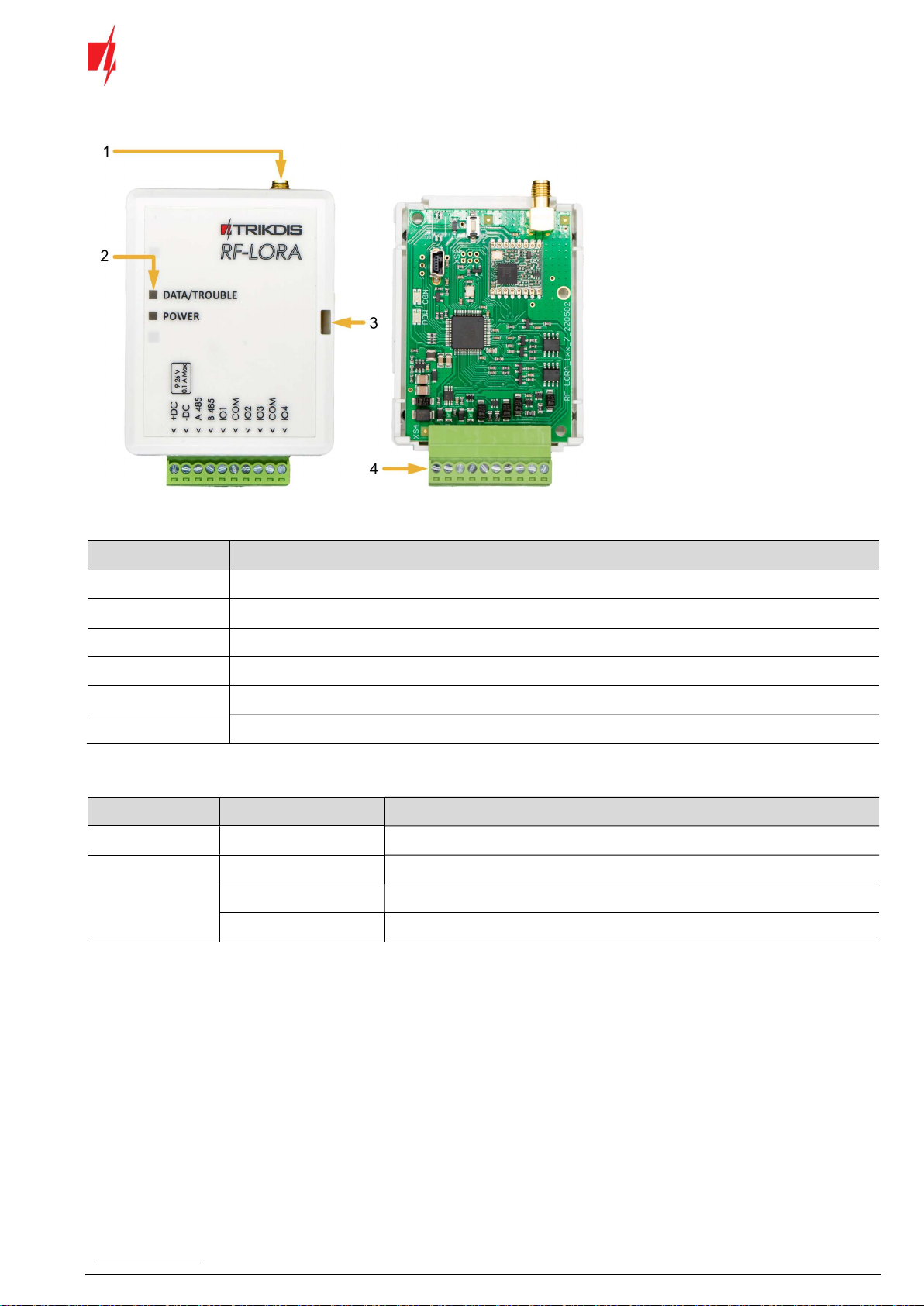
1.2 Expander elements
1. SMA connector for RF
antenna.
2. Light indicators.
3. Frontal case opening slot.
4. Terminal for external
connections.
1.3 Purpose of terminals
Terminal Description
+DC Power terminal (9-26 V DC positive)
-DC Power terminal (9-26 V DC negative)
A 485 RS485 bus A contact
B 485 RS485 bus B contact
IO1-IO4 Not used
COM Not used
1.4 LED indication of operation
Indicator Light status Description
DATA/TROUBLE Red blinking Communication with the module is broken
POWER Off No supply voltage
Green blinking Normal supply voltage level
Yellow blinking Low supply voltage level (≤11.5 V)

www.trikdis.com 6 December, 2022
Transceiver RF
-
LOR
A
2 Wiring schematics
2.1 Fastening
1. Remove the top lid.
2. Remove the PCB board.
3. Fasten the base of the case in the desired place
using screws.
4. Reinsert the board.
5. Close the top lid.
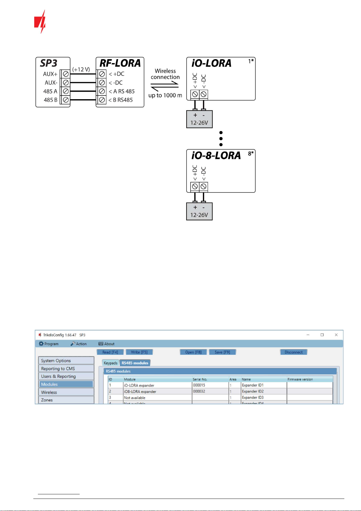
2.2 Schematic of RF-LORA transceiver connection to "FLEXi" SP3 control panel
www.trikdis.com 7 December, 2022
Transceiver RF
-
LOR
A
2.3 Schematics for connecting LORA modules
3 Registering the LORA wireless expander to the control panel “FLEXi” SP3
1. An RF-LORA transceiver must be connected to the "FLEXi" SP3 control panel.
2. Turn on the power supply of the "FLEXi" SP3 control panel.
3. Turn on the power supply to the iO-LORA and/or iO-8-LORA wireless expanders.
4. Launch TrikdisConfig.
5. Connect the "FLEXi" SP3 to a computer using a USB Mini-B cable or connect to the "FLEXi" SP3 remotely.
6. Click the button Read [F4] for the program to read the parameters currently set for the "FLEXi" SP3 control panel. If a
window for entering the Administrator code opens, enter the six-symbol administrator.
7. In the "Modules" list, select "iO-LORA expander" ("iO-8-LORA expander").
8. In the "Serial No." field, enter the serial number of the module.
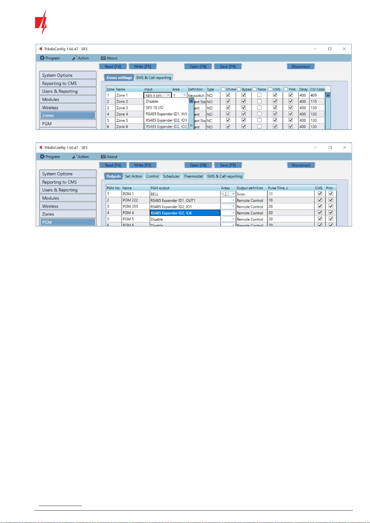
9. In the "Zones" tab, make settings for the expander's input.
www.trikdis.com 8 December, 2022
Transceiver RF
-
LOR
A
10. In the "PGM" tab, configure the expander's PGM output.
11. Once configuration is complete, click the Write [F5] button.
12. Wait for the updates to finish.
13. Click the "Disconnect" button and disconnect the USB cable.
14. Trigger the inputs and switch outputs to test the device.
Table of contents
Other Trikdis Transceiver manuals


Popular Transceiver manuals by other brands


Kenwood
Kenwood TK-880 series Service manual

Communications Specialties
Communications Specialties Fiberlink 5012 user manual

Clegg
Clegg FM-DX owner's manual

Yaesu
Yaesu FT-950 - CAT OPERATION REFERENCE BOOK Reference

Nova Engineering
Nova Engineering NovaRoam 900 user manual

Becker
Becker AR6201 Series operating instructions


