Trikdis RF-HW User manual

Application of Honeywell wireless sensors
with the “FLEXi” SP3 control panel
September, 2022

www.trikdis.com 2 September, 2022
Security control panel
„FLEXi“
SP3
Attention!
Read this user manual carefully.
A representative from the company installing the alarm system will explain which functions of the FLEXi SP3 security module
must be activated to ensure proper protection of the premises.
Copyright © 2022 UAB “Trikdis”. All rights reserved.
Trademarks and patents Other trade names used in this document may be trademarks or registered
trademarks belonging to their respective manufacturers or retailers.
Manufacturer UAB „Trikdis“,
Draugystes g. 17, LT-51229 Kaunas, Lithuania
Version This document is applicable to FLEXi SP3 security modules with firmware
version v1.00 and up.
Certification CE marking
European Union directives 2004/108/EC (EMC directive)
1999/5/EC (conformity directive)
Contact information for inquiries Contact information can be found on the website www.trikdis.c
om

www.trikdis.com 3 September, 2022
Security control panel
„FLEXi“
SP3
Contents
1 Control panel firmware replacement ................................................................................................................................... 4
2 Linking a wireless sensors ..................................................................................................................................................... 6
3 Linking a wireless remote controller (keyfob) ...................................................................................................................... 8
4 Linking a wireless siren ....................................................................................................................................................... 10
5 Linking a wireless keypad 5828 ........................................................................................................................................... 11

www.trikdis.com 4 September, 2022
Security control panel
„FLEXi“
SP3
1 Control panel firmware replacement
The “FLEXi” SP3 control panel firmware must be changed to SP3_xxx2_0114.fw, which will ensure the operation of Honeywell
wireless sensors. The RF-HW wireless transceiver must be connected to the control panel.
Follow the steps below to replace the firmware:
1. Switch on the power supply to the “FLEXi” SP3 control panel.
2. Launch TrikdisConfig.
3. Connect the “FLEXi” SP3 to a computer using a USB Mini-B cable.
4. Open the TrikdisConfig window “Firmware”.
5. Click the “Open Firmware” button and select the SP3_xxx2_0114.fw firmware file.
6. Click the Update [F12] button.
7. Wait for the updates to finish.
8. Disconnect the USB Mini-B cable.
9. Wait 1 minute.
10. Connect a USB Mini-B cable to the “FLEXi” SP3.
11. The TrikdisConfig status bar must contain the number 2 in the control panel name.
12. Switch off the power supply to the “FLEXi” SP3 control panel.
13. Disconnect the USB Mini-B cable.
14. Connect the RF-HW transceiver and the “FLEXi” SP3 according to the diagram.
15. Switch on the power supply to the “FLEXi” SP3 control panel.
16. Wait 1 minute.
17. Connect the USB Mini-B cable to “FLEXi” SP3.
18. Launch the program TrikdisConfig, click the button Read [F4].
19. In the “Modules” window, pick “RF-HW wireless transceiver”.

www.trikdis.com 5 September, 2022
Security control panel
„FLEXi“
SP3
20. In the “Serial No.” field, enter the device’s serial number.
21. Click Write [F5].
22. Disconnect the USB Mini-B cable.
23. Wait 1 minute for the “FLEXi” SP3 and RF-HW to link together.
24. Connect a USB Mini-B cable to the “FLEXi” SP3.
25. Click Read [F4].
26. The firmware version of the RF-HW will appear in the “Modules” window.
27. The RF-HW module is now linked to the “FLEXi” SP3.
28. Disconnect the USB Mini-B cable.
29. Click “Disconnect”.
30. Wait 1 minute.
31. Using TrikdisConfig, remotely connect to the “FLEXi” SP3 control panel.
IMPORTANT: Remote configuration will only work when “FLEXi” SP3:
1. An activated SIM card must be inserted and the PIN code must be entered or disabled.
2. Mobile internet is activated on the SIM card.
3. Protegus cloud service must be enabled.
4. The power must be switched on (“PWR” LED must be green blinking).
5. Must be connected to network (“NET” LED must be green solid and yellow blinking).
32. In the “Remote access” section enter the control panel “IMEI/Unique ID” number. This number can be found on the
device and the packaging sticker.

www.trikdis.com 6 September, 2022
Security control panel
„FLEXi“
SP3
33. Click “Configure”.
34. In the newly opened window click Read [F4]. If required, enter the administrator or installer code.
35. Go to the “Wireless” window.
2 Linking a wireless sensors
Click the “Learn sensors” button.
All wireless sensors can be linked simultaneously.

www.trikdis.com 7 September, 2022
Security control panel
„FLEXi“
SP3
When enrolling sensors, the RF-HW module must be
at least 1 m from the sensors.
1. The “LEARN” LED on the RF-HW module will
flash.
2. RF-HW module - switches to learning mode.
TrikdisConfig will open the sensor binding
window.
3. Insert a battery into the wireless sensor (PIR,
magnetic contact, flood detector, smoke
detector, glass break detector, vibration sensor).
On the RF-HW module, the “LEARN” LED will
flash yellow for a short time (this indicates that
the sensor is enrolled). A new window will open
in TrikdisConfig, in which you need to specify the
type of sensor (PIR, magnetic contact, flood
detector, smoke detector, glass break detector,
vibration sensor).
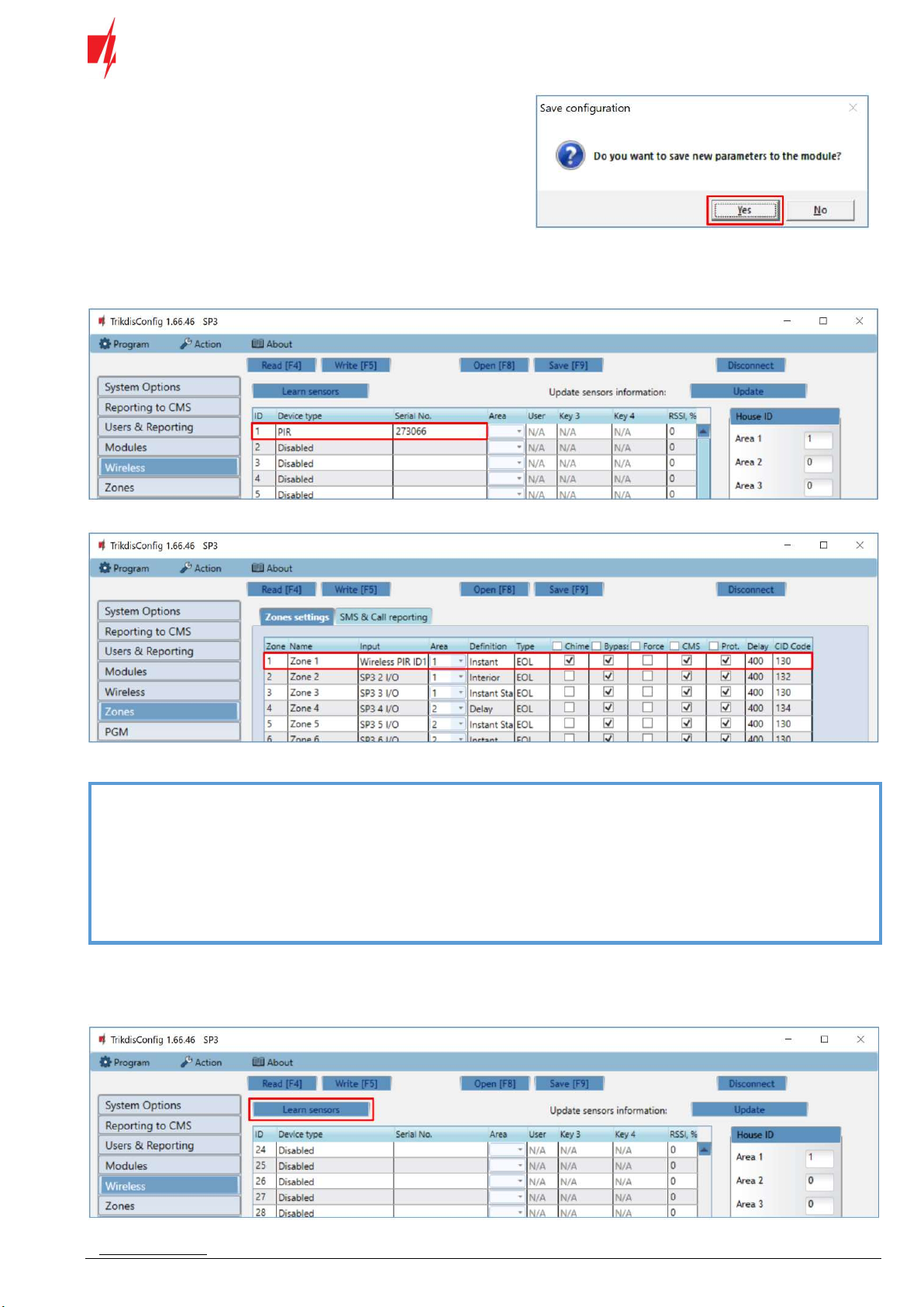
4. Click “Save”.
5. The sensor must be assigned a “Zone Number”
and a “Zone definition”.
6. Click “Save”.
7. Wireless sensor is included in the list of sensors.
8. The “UID” number must match the serial number
of the sensor shown on the sticker on the sensor
board.
9. If you need to add the next sensor, you need to
insert a battery into it. And make the settings
described above.
10. Click “Stop learning” to complete the registration
of wireless sensors.
www.trikdis.com 8 September, 2022
Security control panel
„FLEXi“
SP3
11. Click “Yes” for the sensors to be written to the
“FLEXi” SP3 control panel.
Wait a few minutes. Click Read [F4].
TrikdisConfig will display a list of registered wireless sensors in the “Wireless” window. The “Serial No.” field will list the serial
number that must match the sensor serial number written on the back of the case or on the sensor board.
Check that the sensors are correctly assigned to the “Zones” and “Areas” of the control panel (“Zones” window).
If you set zone “Type” EOL-T, then the sensor tamper monitoring mode will be enabled.
Note: To delete wireless sensors from the “FLEXi” SP3’s memory:
1. Launch TrikdisConfig.
2. Connect the „FLEXi“ SP3 to a computer using a USB Mini-B cable or connect to the „FLEXi“ SP3 remotely.
Click the Read [F4] button.
3. In the TrikdisConfig window “Wireless”, in the column “Device type”, select “Disabled” instead of the
“Wireless sensor” that you wish to delete and click Write [F5]. The wireless sensor is now removed from
the “FLEXi” SP3’s memory.
3 Linking a wireless remote controller (keyfob)
Click “Learn sensors”.

www.trikdis.com 9 September, 2022
Security control panel
„FLEXi“
SP3
All wireless keyfobs can be linked simultaneously.
When enrolling keyfob, the RF-HW module must be
at least 1 m from the keyfob.
1. The “LEARN” LED on the RF-HW module will
flash.
2. RF-HW module - switches to learning mode.
TrikdisConfig will open the sensor binding
window.
3. Press and hold any button on the keyfob for a few
seconds. Release the button. On the RF-HW
module, the “LEARN” LED will flash yellow for a
short time (this indicates that the keyfob is
enrolled). A new window will open in
TrikdisConfig, in which you need to specify the
device type “Keyfob”.
4. Click “Save”.
5. In the “Area” field, specify the partition of the
security system that the keyfob will control (Arm
/ Disarm). In the “User” field, enter the user
number to which the keyfob will be assigned.
6. Click “Save”.
7. Wireless keyfob is included in the list.
8. The “UID” number must match the serial number
of the keyfob, which is indicated on the sticker on
the back of the keyfob.
9. If you need to add the next keyfob, you need
press and hold any button on the keyfob for a
few seconds. Release the button. And make the
settings described above.
10. Click “Stop learning” to complete the registration
of wireless keyfobs.
www.trikdis.com 10 September, 2022
Security control panel
„FLEXi“
SP3
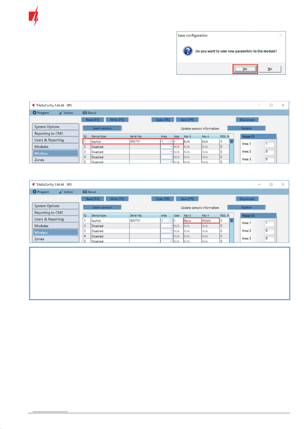
11. Click “Yes” to write the settings to the "FLEXi"
SP3 control panel.
Wait a few minutes. Click Read [F4].
In TrikdisConfig, in the “Wireless” window in the “Device type” field, the name “Keyfob” should appear. The number should
appear in the “Serial No” field and should match the keyfob serial number written on the case.
1 and 2 keyfob buttons have fixed functions (Arm/Disarm). You can assign additional functions to the keyfob’s buttons 3 and 4
(Arm, Disarm; Silent alarm; Panic alarm; PGM control).
Note: To delete wireless keyfob from the “FLEXi” SP3’s memory:
1. Launch TrikdisConfig.
2. Connect the „FLEXi“ SP3 to a computer using a USB Mini-B cable or connect to the „FLEXi“ SP3 remotely.
Click the Read [F4] button.
3. In the TrikdisConfig window “Wireless”, in the column “Device type”, select “Disabled” instead of the
Keyfob that you wish to delete and click Write [F5]. The keyfob is now removed from the „FLEXi“ SP3’s
memory.
4 Linking a wireless siren
1. Remove the siren cover.
2. Use DIP switches 4-8 to set the appropriate “House ID” code (01-31) for the siren.
3. Enter the siren “House ID” code in TrikdisConfig. The wireless siren can be assigned to several areas.

www.trikdis.com 11 September, 2022
Security control panel
„FLEXi“
SP3
Click Write [F5] after making the changes.
Note: To delete wireless siren from the “FLEXi” SP3’s memory:
1. Launch TrikdisConfig.
2. Connect the „FLEXi“ SP3 to a computer using a USB Mini-B cable or connect to the „FLEXi“ SP3
remotely. Click the Read [F4] button.
3. In the TrikdisConfig window “Wireless”, in the column “House ID”, enter “0” instead of the “House ID”
code and click Write [F5]. The wireless siren is now removed from the „FLEXi“ SP3’s memory.
5 Linking a wireless keypad 5828
1. Press and hold the [1] and [3] keys simultaneously for five (5) seconds. The display alternately flashes “00” and two
dashes (- -).
2. Press [1]. The display alternately flashes “t1” and the 2-digit “House ID” code.
3. Enter the two-digit “House ID” code (01-31).
4. Press [#].
5. Press [*] [*].
6. Enter the same “House ID” code in TrikdisConfig.
Click Write [F5] after making the changes.
Note: To delete wireless keypad from the “FLEXi” SP3’s memory:
1. Launch TrikdisConfig.
2. Connect the „FLEXi“ SP3 to a computer using a USB Mini-B cable or connect to the „FLEXi“ SP3
remotely. Click the Read [F4] button.
3. In the TrikdisConfig window “Wireless”, in the column “House ID“, enter “0” instead of the “House
ID” code and click Write [F5]. The keypad is now removed from the „FLEXi“ SP3’s memory.
Table of contents
Other Trikdis Transceiver manuals


Popular Transceiver manuals by other brands


Kenwood
Kenwood NX-1200NE2 user manual

Schweitzer Engineering Laboratories
Schweitzer Engineering Laboratories SEL-3031 instruction manual

National Instruments
National Instruments PXIe-5820 Getting started guide

Kenwood
Kenwood TK-3212 Service manual

Lathem
Lathem ATX Installation & user guide

Kongsberg
Kongsberg SIMRAD TP90 installation manual