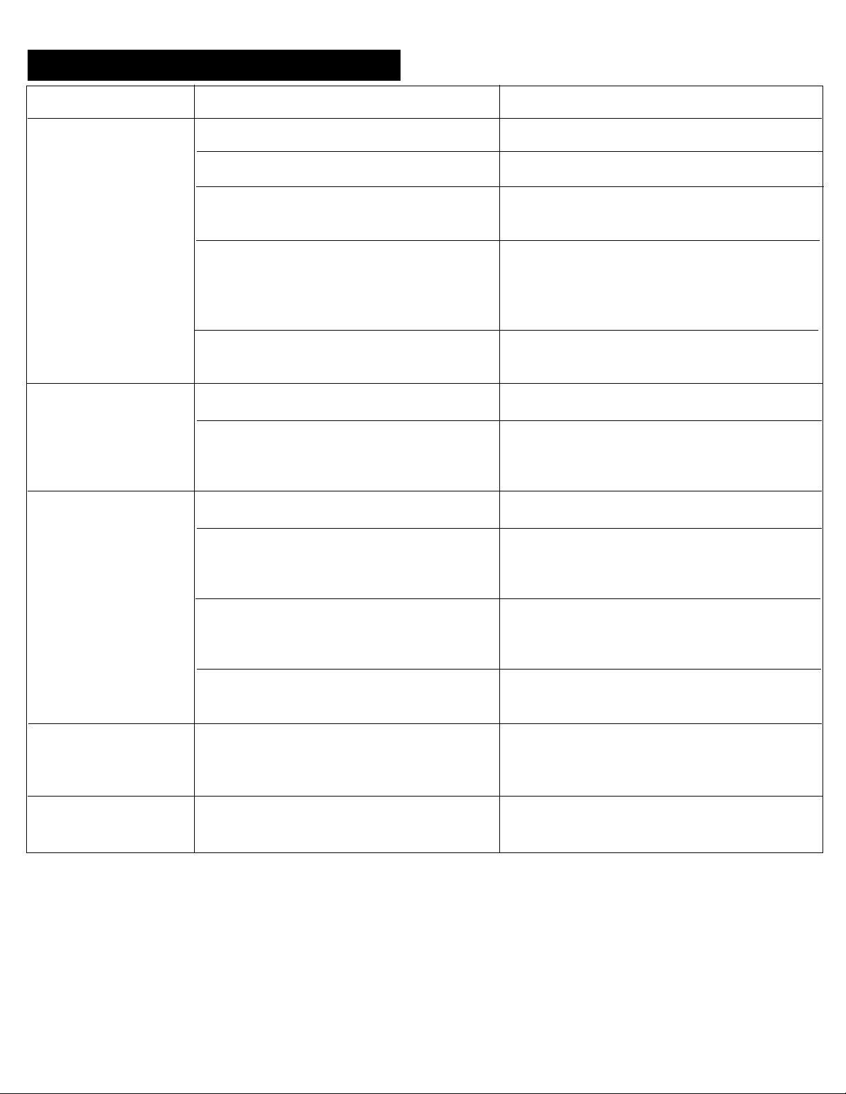
4. STRIKE ADJUSTMENT
5. BASIC OPERATION
Carefully close door. Door should easily latch
shut. If door does not shut tightly enough for
desired sealing, adjust strike as follows:
1. Use a pencil to mark the existing position
of the strike plate on the door jamb.
2. Loosen the strike plate mounting screws
so that strike plate can slide on door jamb.
3. Slide strike plate inward no more than
1/16”.
4. Tighten strike plate mounting screws so
that closing of door and vibration will not
move strike plate. Do not tighten
excessively as stripping of the threads
may result.
5. Carefully close door and check for proper
sealing, door closing effort, and latch
operating efforts. The strike should not
be adjusted in so far that excessive
force (25 pounds maximum) is required
to push the door shut to latch. The
door should be able to be pushed shut
by hand without slamming. If adequate
sealing is still not achieved go back to
step 1.
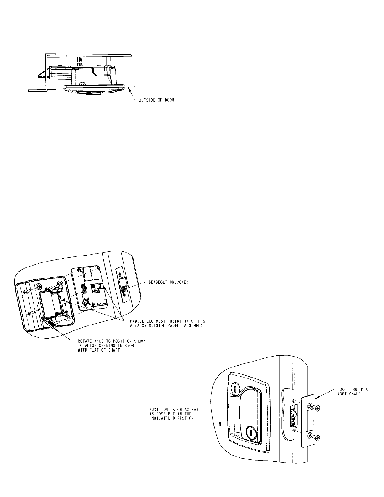
OPERATION OF THE PADDLE LOCK:
The paddle can be locked by rotating the
lock cylinder in the paddle clockwise 1/4
turn and can be unlocked by rotating the
lock cylinder counterclockwise 1/4 turn.
When locked, the outside paddle will not
be able to be pulled. When locked, the
inside paddle will still be able to be pulled
and open the door. If the latch is locked
with the door open, it can be shut and will
stay locked. The paddle lock can not be
locked or unlocked from the inside.
OPERATION OF THE DEADBOLT
FROM THE OUTSIDE:
From the outside the deadbolt can be
locked and unlocked only with the keys
provided for the customer. It can’t be
locked and unlocked with the master key.
To lock (extend) the deadbolt, rotate the
key a little more than 1/4 turn clockwise.
A light click should be felt and heard. The
lock cylinder will have to be returned back
to center to remove the key. To unlock
(retract) the deadbolt, rotate the key a
little more than 1/4 turn counterclockwise.
A slight click should be felt and heard.
The lock cylinder will have to be returned
back to center to remove the key. The
deadbolt must be operated while the door
is shut. If the deadbolt is locked
(extended) while the door is open, it will
not shut.
OPERATION OF THE DEADBOLT
FROM THE INSIDE:
The deadbolt can be locked and unlocked
from the inside by rotation of a red knob
near the paddle. This knob can be rotated
a little more than 1/4 turn clockwise to
lock and a little more than 1/4 turn
counterclockwise to unlock. A designation
is provided on the inside plate to show the
direction to lock and unlock.
LATCHING/UNLATCHING:
The latch uses a single latching position that
is achieved by the engagement of the
plunger in the opening of the strike plate. The
deadbolt engages into this same opening
and if extended, will prevent closing and
opening of the door.
USE OF A MASTER KEY:
If the lock cylinder in the paddle has a letter
stamped on its face, it can be unlocked and
locked with a master key. For example, if it
has a “1R” stamped on its face, a “1R” series
master key will lock and unlock the paddle.
The master key will not lock or unlock the
deadbolt. If there is not a letter stamped on
the face of the paddle lock cylinder, it cannot
be operated with a master key.