TRIMETALS Protect-a-cycle User manual
ASSEMBLY INSTRUCTIONS
issue number: 1, October 6th 2008

2
FOR FASTER ASSEMBLY WE RECOMMEND
THE USE OF AN ELECTRIC SCREWDRIVER
STEP 1
- For ease of assembly we recommend that the base be assembled
on a flat surface and care must be taken to ensure the base is
square before the fasteners are fully tightened. Check squareness by
measuring from corner to diagonal corner - and then repeat for the
other side - the measurements should be the same.
- The product is designed to be bolted down onto a flat and level
concrete base with a recommended thickness of 100mm (4”).
The concrete used must be of a grade offering compatible
resistance to attack.
STEP 2
- From now on all fasteners should be loosely fixed. Do not fully tighten
them until you are told to do so.
- When you see the Red Spanner icon
tighten indicated fasteners.
- All bolts on this page are part 14 and all nuts are part 36.
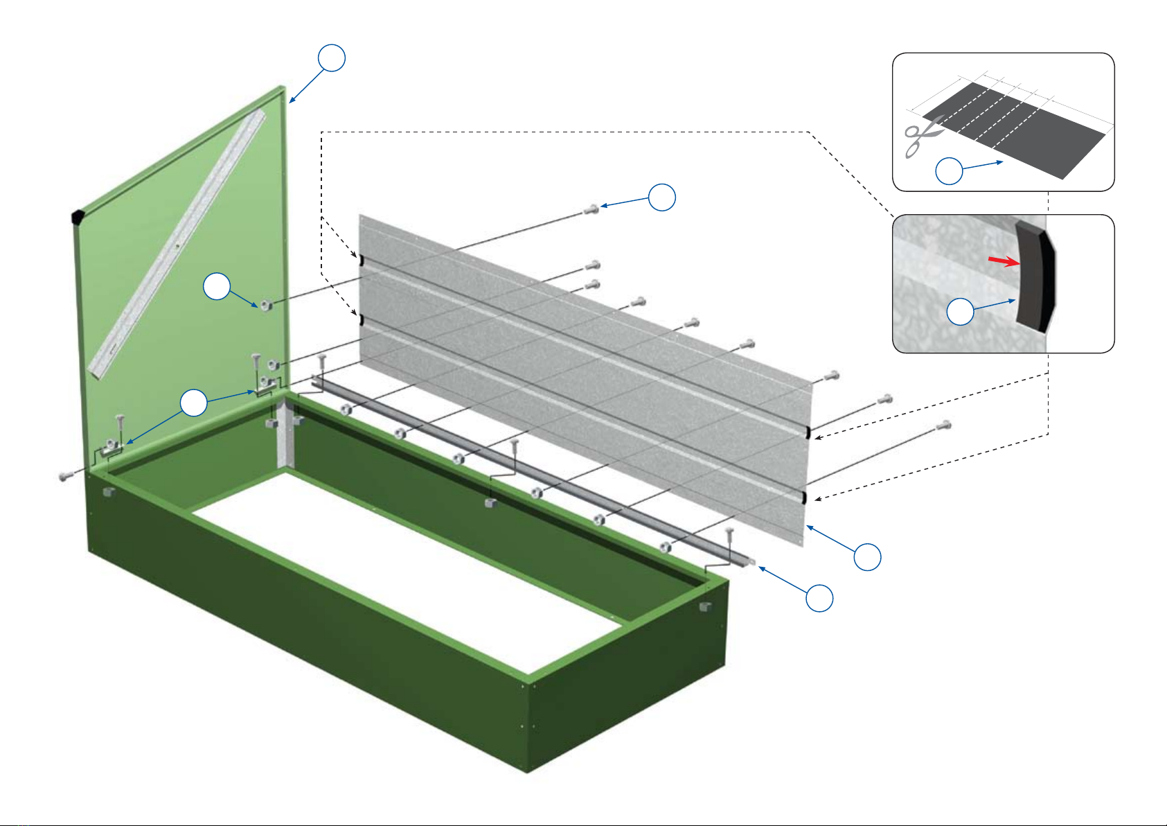
STEP 3
- Remember to only loosely fix the fasteners until you are told
to tighten them.
- Be sure to place part 34 the correct way round - see small
detailed diagram.
STEP 4
- See illustration
STEP 5
- See illustration
STEP 6
- All bolts on this page are part 14 and all nuts are part 36.
- Make sure part 20 (top back panel) is inserted into top rail (part 34)
as illustrated.
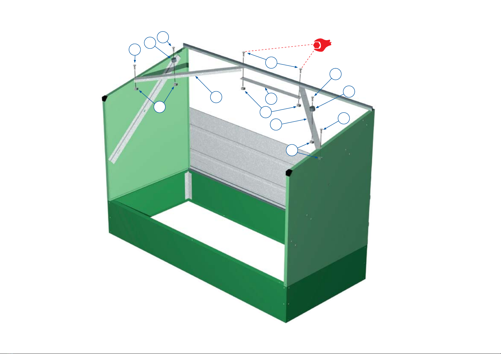
STEP 7
- The left hand link arm part 12L (which is marked by a circle of coloured tape) must be fitted
to the left hand side of the unit as shown in the diagram.
- Identify part 12L and feed one washer (part 13) onto it followed by a link arm bracket (part
11). Push both round until they are on the length of tube that has two holes pierced through
it and so that the raised end of the bracket (part 11) will be facing away from the unit when
attached. Feed the link arm (part 12L) through the hole in the left hand side panel (part 4L)
from the outside and then through the side panel stiffener located on the inside of the side
panel (part 4L) then feed another washer (13) onto the link arm (part 12L) from the inside
and secure the assembly with two clips (part 19) through the two holes provided in the link
arm (12L), one on the outside of the unit and one on the inside. Secure the link arm bracket
(part 11) with parts 14 and 36.
- Repeat the above procedure to attach the right hand link arm (part 12R).
- In stage 7d make sure the hook on part 16 is facing the side panel
(part 4) and do not over tighten the nut (part 35) at any time as the spring lever (part 16)
must move freely.
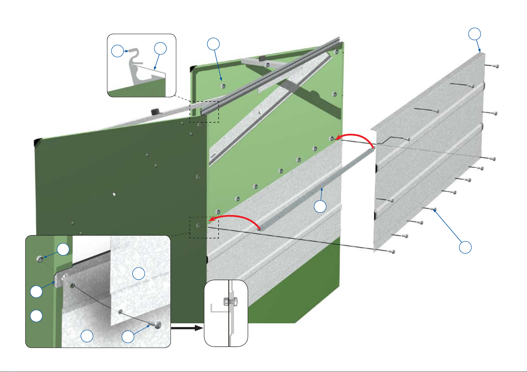
STEP 8
- Slide part 9 into the top rail (part 34) and secure with the end stop (part 23) and thread
forming screw (part 17).
STEP 9
- Note that part 27 is placed on the back of door panel.
- The torsion bar (part 25) should already be in place at the back of the door.
- Push the left hand link arm (12L) through the hole in the side of the door panel (part 9) and
into the torsion bar (part 25), repeat this on the right hand side and twist the bar to line up
with the holes (either end) in the link arms then screw in the thread forming screws (part 17)
to secure. Do not close the door until these screws are fully tightened.
- Identify the weatherstrip (part 22) and apply to side panels (part 4) along both the top and
front edges. Strip the backing off a little at a time and starting at the top of the side panel
butt the strip up against the top rail (part 34) and stick along the top edge of the side panel
down to the plastic corner moulding. Cut weatherstrip (part 22) and continue from below the
corner moulding down to the front base section. Repeat for the other side.
- Both springs (part 18) are identical; one hooks upwards and the other hooks downwards.
- Note that as fastener packs are standard for all units you may have some fasteners spare
after completion of assembly.
IMPORTANT ATTENTION
A Before commencing assembly
check parts in box with
illustrations on components
page and thoroughly read the
assembly instructions.
B These products must be secured
to a hard concrete base
(see Step 1).
C Extra care should be taken to
avoid cuts and abrasions from
exposed edges during assembly.
We strongly recommend the use
of protective gloves.
D We recommend that two people
work on the assembly.
E Precautions should be taken
when storage units are being
used in exposed areas subject
to high wind speeds. In these
circumstances the products
should be locked and care
should be taken if they are to be
opened to avoid damage.
Please ensure that children are
always supervised when using
this product
F For additional weatherproofing
we recommend the use of a
mastic type sealant that can be
used to create a seal between
panels.
G In the unlikely event that this
product has been delivered
damaged, there are any parts
not included or you are having
difficulties with assembly please
contact Trimetals direct NOT THE
RETAILER. We will endeavour to
correct any problems as quickly
as possible.
HELP LINE:
Tel: +44(0)1258 459441
Fax: +44(0)1258 480408
ASSEMBLY INSTRUCTIONS (to be read in conjunction with illustrations)

3
STEP 10
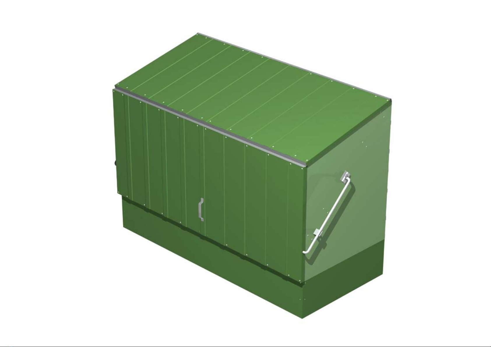
- Completed assembly view
STEP 11
- Move the assembled unit on top of the concrete base (using two people) and use a pencil
to mark the position of the four holes in the product’s base (two holes in each of the long
bases). Carefully move the unit to one side as you will now need to drill the holes you have
marked on the concrete. Firstly drill holes (always wear goggles) with a 10mm ø masonry
drill to a depth of 10mm then re-drill the holes with a 14mm ø masonry drill to a depth
of 70mm. Vacuum the dust from the holes.
- Select the four M8 anchor bolts (these are gold in colour) and unscrew the bolts from
their expanding anchors. Place the bolts (with washers) to one side and then firmly push
the four anchors into the holes you have drilled.
STEP 12
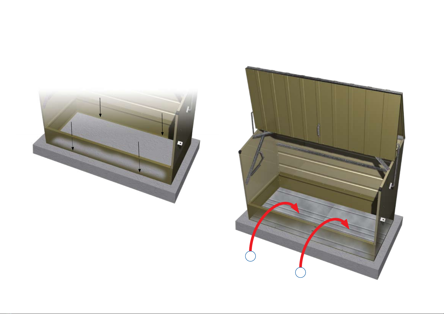
- Carefully move the unit back into place lining up the holes in the base with those you have
drilled. Place the right hand metal base inside the unit as shown (make sure that the two
large holes punched in the metal floor are toward the front of the unit as this is where the
ground anchor will be placed).
- Place the left hand metal base inside the unit (again with the two large holes nearest the
front of the unit) then move both floors so the four holes on the long edges line up with
the holes you have drilled in the concrete (the metal floors will overlap slightly).
STEP 13
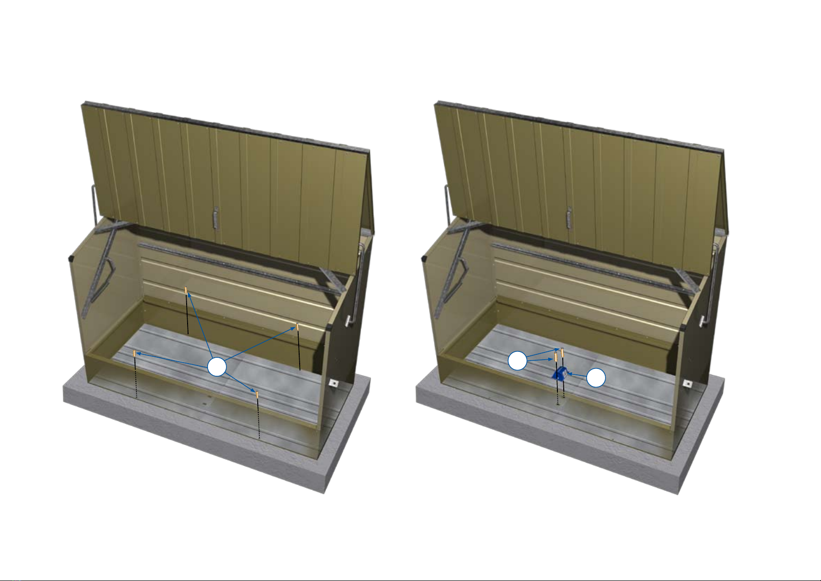
- Select the four M8 bolts (with washers) and place them through the metal floors and
down through the base then screw into the expanding anchors. Using a spanner tighten the
bolts (it is recommended that you tighten each bolt evenly in turn until all are as tight
as possible to ensure the base lays flat).
STEP 14
- You now need to drill through the center of the two large holes in the metal bases (always
wear goggles). Use a 12mm ø masonry drill go down to a depth of 10mm then re-drill
holes using a 16mm ø masonry drill to a depth of 75mm. Vacuum the dust from the holes.
Unscrew the two bolts from the expanding anchors and place the bolts through the ground
anchor then reattach the anchors on the other side by a few turns. Place the ground anchor
over the metal base and align with your drilled holes. Push the two M10 anchor bolts
through the ground anchor into the holes then use the Allen key provided to fully tighten
evenly. Place the steel ball bearings on top of the two socket heads and hammer into place
(this prevents the bolts from being undone).
STEP 15
- The security cable is then used to secure your bike(s) to the ground anchor. Place the cable
through both the frame and wheel of the bike(s) for increased security.
STEP 16
- With the door held open measure in 250mm from the side of the door (on the inside) and
place the hasp centrally on this point. Hold the hasp against the bottom section of the door
(on the inside) and keeping it level mark where the two holes are to be drilled.Remove the
hasp and drill carefully through the part of the section you have marked (with the drill bit
provided). Drill through the section on the back of the door – do not drill
through the door itself.
- Secure the hasp in position using the bolts and locknuts provided as shown above (make
sure you place the backplate in position).
- Close the door and hold the staple against the base. Line the staple up centrally with the
hole in the hasp and mark the four holes. Remove the staple and drill through the base
using these four holes as a guide.
- Secure the staple as shown (make sure you place the backplate in position).
Repeat for other side.
Should you have any problems then please ring our helpline: 01258 459441.

4
12L
12R
4L
4R
6
26
13
23
11
18
10
7b
9
2
30
22
1 x2
2 x2
3 x4
4L x1
4R x1
5 x2
6 x1
7 x2
7a x1
7b x2
8 x2
9 x1
10 x4
11 x2
12L x1
12R x1
13 x4
16 x2
18 x2
19 x4
20 x1
21 x2
22 x2
23 x2
26 x1
27 x1
30 x1
34 x1
Part No
Bike
Store
534
1
7a 7
20
16
21
3
8
35 x28
Tighten
nuts & bolts
33 x2
24 x2
31x26
14x53
17 x4
36 x55
19
27
4 x M8 Rawlbolt
2 x M10 Rawlbolt (in anchor box)
1 x Right hand metal base section
1 x Left hand metal base section
1 x Ground anchor
1 x Cable lock
3 x Padlocks
2 x Hasps (with fasteners)
A
B
C
D
E
F
G
H
Drill bit (for step 16 ONLY)

5
Step1
Bike store
2
1
1
2
3
31
35
6
Step 2
Bike Store
Îx
£ä
£ä
£ä
£ä
Îx
£ä
£ä
£ä
£ä
{ä
10
5
6
14
36
30
30
4L

7
Step 3
Bike Store 14
34
14
14
36
14
7b
36
10
14
4R
7b
36
36
14
34
8
Step 4
Bike Store
14
14
33
8
36 36
14
8
33
7a
36
7
7

9
Îx
£ä
£ä
£ä
£ä
Îx
£ä
£ä
£ä
£ä
{ä
30
Step 5
Bike Store
30
20
20
10
Step 6
Bike Store
36
20
5
14
4R
20
36
14
20
6
34
5

11
12L
14
21
21
36
36
14
12R
Step 7
Bike Store
Step 7b
12L
Step 7a 13
11
Step 7c
19
14
36
4L
4R
12L
Step 7d
16
19 13
24
35
It is critical that the
correct link arm is used
on each side of the unit
- 12L (with the circle of
coloured tape) must be
used on the left side of
the unit as shown.

12
23
17
9
Step 8
Bike Store

13
Step 9
Bike Store
26
35
31
27
25
17
17
18
18
18
16
24
35
24
35
16
9
12R
17
14
Step10
Bike Store
15
Step11
Bike Store
Step12
Bike Store
D
C
16
Step13
Bike Store
Step14
Bike Store
AB
E

17
Step15
Bike Store
Step16
Bike Store
F
G
E
G

18
GUARANTEE
EXCLUSIONS
Trimetals Ltd will not be liable under the Guarantee for:
1.1 Explosion, Fire Lightning, Theft and those other perils normally provided by household contents insurance.
1.2 Accidental damage including scratching, bruising or denting or from the direct application of a tool.
1.3 Mishandling or neglect by the Registration Holder or any member of his family, household or staff or use of the
product not in accordance with the manufacturer’s instructions.
1.4 Failure of the Registration Holder to maintain or service the product in accordance with the manufacturer’s
instructions.
1.5 Spillage of chemicals or hazardous substances causing erosion or discolouration of parts, or storage of items that
are not done in accordance with the manufacturer’s written instructions and normal laid down codes of practice.
1.6 War, Civil War, Hostilities (whether war declared or not), riots, strikes or civil commotion.
1.7 Ionising radiations, the hazardous properties of nuclear material or sonic bangs.
1.8 All fixings and fasteners.
2 Normal wear and tear, the cost of routine maintenance, adjustments or modifications or loss or damage arising
therefrom.
3 Loss of use of the appliance or consequential loss of any nature.
4 The cost of materials and labour charges for which any manufacturer, supplier or any other person may be held
responsible under the terms of the Sale of Goods Act or any Guarantee or Warranty.
5 Cost incurred outside the United Kingdom.
6 If the goods have been signed for as being received in good condition.
CONDITIONS
1 In the event of failure of the product Trimetals Ltd or their agents may at their option repair or replace the defective
part(s) or pay in cash for the cost of repair excluding labour and transport charges. In the event of the product as
a result of failure being deemed beyond economic repair Trimetals Ltd will pay the market value of the product
immediately prior to breakdown.
2 Trimetals Ltd shall in no case be bound to accept notice of any transfer of interest and nothing contained in our
Guarantee shall give any rights against Trimetals Ltd to any other person than the original Registration Holder who
shall be a private individual.
3 At the request of Trimetals Ltd the Registration Holder shall do and concur in doing all such acts and things as
Trimetals Ltd may reasonably require with a view to obtaining compensation for failure covered by this guarantee
and to enforce any rights that the Registration Holder may have against anyone in respect of any failure whether or
not payment has been made by Trimetals Ltd.
4 The Certificate of Registration will be rendered void in the event of the Certificate Holder’s fraud, non-disclosure,
alteration of risk or any attempt threat, or the use of the product other than normal domestic purposes.
5 These conditions in no way affect your statutory rights.
6 Terms and Conditions are governed by English law and you submit to the non-exclusive jurisdiction of the English
Court.
CLAIMS PROCEDURE
In the event of damage contact Trimetals Ltd on +44 (0)1258 459441. Please have the Model and Serial numbers
available when you call plus the details or your registration card and copy of payment receipt. You will then be advised
of the procedure in your area.

19

Trimetals has been established for 40 years and is firmly placed as Europe’s leading
producer of quality metal storage buildings and metal garden sheds.
The unique designs which maximise strength and rigidity are unmatched by any other
manufacturer and our 25 year panel guarantee is your assurance that our range of
buildings are the very best available.
Please do not confuse our products with cheap and flimsy substitutes or plastic
alternatives. Our buildings are strong, secure, fire resistant and maintenance free,
giving you real value for money. We pride ourselves in our reputation for superior
products and are sure you will be completely satisfied with any product in our
extensive range.
www.protectacycle.co.uk
Sunrise Business Park, Higher Shaftesbury Road,
Blandford Forum, Dorset, DT11 8ST. UK
Tel: +44(0)1258 459441
Fax: +44(0)1258 480408
Email: [email protected]
Web: www.trimetals.co.uk
This manual suits for next models
1


