Merida Procraft Lenker User manual

Installation and
operating instructions
Cockpit
Thank you for purchasing a
MERIDA component.
About these instructions
Carefully read and follow these installation and
operating instructions before use. Keep these
instructions for future reference.
These instructions are valid for the following
MERIDA components (Fig. an example):
1. Handlebar grips
2. Spacer
3. Ahead stem
4. Bar ends
5. Stem steerer tube
6. Handlebar adjuster
7. Handlebar
8. Headset
Special features
All carbon components require special care and
attention. The material is very durable and has a
low weight. However, the material is also very
brittle. Therefore, have you bicycle inspected by
your dealer following accidents or other incidents.
1. Intended use
The majority of MERIDA components are
designed for use on racing, trekking, and
mountain bikes, and their typical use.
The majority of stems are designed for use
exclusively with threadless fork steerers and so-
called Aheadset®headsets.
Use in combination with threaded fork steerers
can lead to sudden failure, resulting in a crash.
The models with steerer tube are suitable for use
in conventional threaded forks.
Before your first ride
Do not file or drill and holes in the components as
this damages their structure and voids the
warranty.
Adjust your bicycle so that you can reach the
brake levers at all times.
Carbon
After being overstressed, a previously damaged
carbon component may fail with continued use
without warning.
If your MERIDA carbon component has been
exposed to such stress, take your bicycle to your
MERIDA dealer. Damaged carbon components
must never be fixed or repaired! They must be
replaced immediately.
Carbon components must never be exposed to
high temperatures. Therefore, never have them
painted. Avoid storage near to heat sources.
Carbon components have a limited life cycle.
Therefore, replace the handlebars and stems at
regular intervals, as a precaution.
Ensure that clamp areas are absolutely free of
grease and lubricant when a clamping surface is
made of carbon. Use a special carbon assembly
paste for the assembly.
2. General assembly instructions
Only use MERIDA components that are designed
to be used together. MERIDA assumes no
responsibility for the combination of a MERIDA
handlebar with an unsuitable stem, or MERIDA
stems and bar ends with an unsuitable
handlebar.
If you do, however, use components from
another manufactures, use the clamp diameters
found in their manuals to ensure their safe use
with MERIDA components.
Check all clamp areas of the components for
burrs and sharp edges prior to assembly. Ask
your MERIDA dealer to check any components
with such burrs or sharp edges. When you
replace the handlebar, also inspect the old
handlebar for damage.
3. Aheadset®stems
Check the clamp diameter.
When using a larger stem, use a suitable
reducing sleeve.
Make sure that the slots of the stem and sleeve
are positions above each other, and that the slot
of the sleeve is facing backward.
If you are replacing the stem on a fork, check the
clamp area for damage. Carbon clamp areas
must be absolutely free of grease.
Use carbon paste on the clamp areas instead.
Lubricate the thread and the head contacts of the
steerer clamping bolts with a high-quality
lubricant. Keep lubricants away from the clamp
areas of the fork and stem. Apply a thin layer of
carbon paste to the fork’s clamp area. Slide the
stem onto the fork.
Depending on the steerer tube length and the
desired stem position, you may have to insert
spacers on the fork steerer above the headset,
and/or on the stem.
Danger
Indicates essential safety
instructions.
Note
Indicates additional
information.
8
6
8
5
4
12
7
3
Note
If you have any questions,
contact your MERIDA dealer.
Danger
Never use bar ends or clip-on/
aero bars with carbon
handlebars, unless the
handlebar is approved for
them.
Danger
Each of the following
instructions must be strictly
observed.
Non-observance of these
instructions may lead to the
failure of the components
and result in an accident.
1
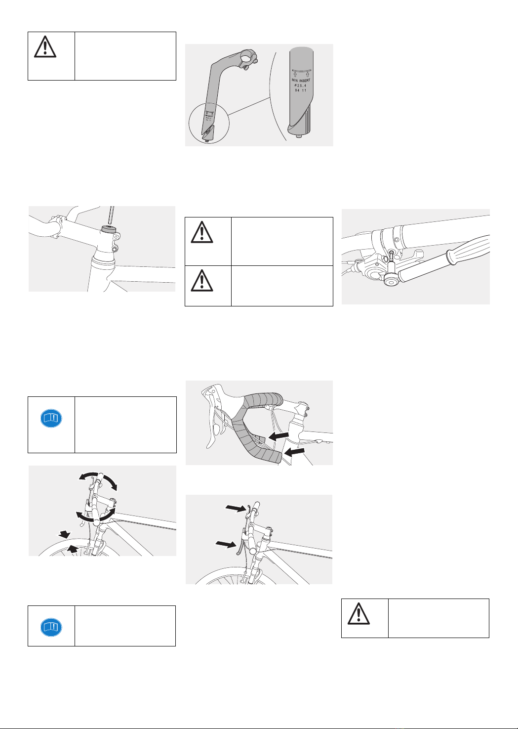
Spacers are available in different heights and
must be stacked so that the steerer tube ends 2–
3 mm below the top edge of the stem. The
maximum height of the installed spacers must not
exceed 40 mm. Observe the fork manufacturer’s
guidelines.
The stem must provide support for a sufficient
length of the steerer tube. This ensures reliable
clamping if the clamping bolts of the steerer tube
are clamped to the prescribed torque value.
3.1. Adjusting the Aheadset®
headset
Open the side clamping bolts of the stem tube.
Adjust the headset by carefully turning the top
sunk screw. The screw is only used for adjusting
the bearing play.
Align the stem with the front wheel so that the
handlebar is not at an angle to the front wheel
when it is pointing straight ahead. Stand over the
top tube and look down over the stem to the front
wheel to check the alignment. Tighten both
clamping bolts alternately. The recommended
tightening torques can be found marked near the
bolt.
The handlebar/stem units must be checked for
resistance to torsion and the torques specified on
the components must be observed when
tightening.
In case of doubt, contact your MERIDA dealer.
4. Conventional stems
Open the stem spindle. Slide the stem tube into
the head tube on the frame.
Pay attention to the maximum extension height.
The stem must not be askew.
For max. torque, refer to the information on the
stem.
If the seat can be twisted, you must tighten the bolt.
5. Mounting the handlebar
The chosen stem must always have the correct
clamp diameter. During mounting, the handlebar
should sit centrally in the handlebar clamp area.
If the handlebar cannot be inserted without the
application of force and there is play between the
two components, contact your MERIDA dealer.
On a road bike, the straight piece of the drops
should be positioned parallel to the ground or
angled slightly downward.
Mountain bike and trekking handlebars are
angled at an ergonomic hand position.
Tighten the greased bolts of the handlebar clamp
a few turns with your fingers. Turn all the bolts
with an Allen key until the upper and lower
clamping slots of the handlebar clamp between
the stem faceplate and stem body are the same
width. Use a torque wrench to alternately and
gradually tighten the bolts to the lower torque
limit. With a 4-bolt faceplate, tighten the bolts
evenly in a cross pattern.
Refer to the information on the stem for the
torque.
Mounting the controls
Examine the clamp areas of the shifter/brake
levers, handlebar/remote levers, and grips (Lock-
On grips) for burrs and sharp edges. Note the
limitation of the handlebar clamp area, if present.
Loosen the clamping bolts as much as possible
before sliding them onto the handlebar. Avoid
rotational movements during assembly. Tighten
the bolts again.
After aligning the controls and grips, tighten the
clamping bolts to the lower limit of the
recommended tightening torque. If the controls or
grips still do not clamp tightly, increase the torque
until you reach the upper torque limit specified by
the component manufacturer. If they can still be
twisted, contact your MERIDA dealer.
6. Adjusting the handlebar height
with Aheadset®
With the Aheadset®system, the stem is part of
the headset system. To adjust the position, the
stem must be dismounted and remounted. If the
stem is changed, the bearing must be
readjusted – see “3.1. Adjusting the Aheadset®
headset” on page 2. The height of the handlebar
can be adjusted by changing the spacers.
Remove the bolt for the bearing preload at the top
of the steerer tube and remove the cap. Loosen
the bolts on the side of the stem and pull the stem
out of the fork. You can now remove the spacers.
Place them back on the steerer tube above the
stem to position the handlebar at the desired
height.
To turn the stem around, the bolts clamping the
handlebar need to be loosened. In the case of
stems with caps, the handlebar can simply be
removed; otherwise, the handlebar controls need
to be dismantled. Turn the stem around and
mount it. Check that the Bowden cables tense
and do not limit the steering angle.
Check the seat of the stem. If the stem twists,
increase the torque to the maximum permitted
torque, or reassemble the stem.
Danger
The space between the top of
the stem and the upper edge of
the steerer tube should not
exceed 2–3 mm.
Note
For forks with carbon steerer
tubes, make sure that there is a
cone mechanism inside as a
counter-bearing for adjusting
the headset.
Note
If the stem cannot be clamped,
the components are not
compatible.
Danger
Never ride a bicycle whose
stem has been pulled out
beyond the maximum
extension height mark.
Danger
Never open the head nut of the
headset bearing. This changes
the bearing play.
Danger
Tighten screws and bolts
correctly.
2
Adjustable Aheadset®stems
With adjustable MERIDA Aheadset®stems, the
height can be varied via the tilt adjustment of the
front stem area.
Loosen the side bolt of the pawl 3–5 turns and
open the steerer tube clamp. Do not remove the
bolt completely. Slide the bolt to the opposite side
of the head. Adjust the movable stem. Slide the
loosened adjusting part back into the stem until
the pawl engages with the teeth of the gear.
Tighten the bolt. For maximum torque, refer to
the information on the component.
Conventional stems
To adjust conventional stems, open the stem
spindle 2–3 turns. With Allen screws, the key
must be inserted into the screw heads. Hit the
tool with a rubber mallet.
Do not put the stem out beyond the marking on
the tube. Align the handlebar again so that it is
not askew when riding straight ahead. Retighten
the stem spindle. For maximum torque, refer to
the information on the component.
Adjustable conventional stems
With adjustable conventional MERIDA stems
with side adjustment bolts, the height can be
varied via the tilt adjustment of the front stem
area.
Loosen the side bolt of the pawl approx. 3–5
turns until the teeth release. Do not unscrew it
completely. Slide the bolt to the opposite side of
the head, and now adjust the stem. Reinsert the
adjusting part until the pawl engages. For
maximum torque, refer to the information on the
component.
With adjustable conventional stems with an
adjustment bolt on the bottom, the tilt is set by
a mechanism on the bottom. The procedure is
similar, but the bolt cannot be removed
completely.
Bar ends
Bar ends offer additional grip options. Ensure that
the handlebar is suitable for use with bar ends
before mounting them.
The clamp areas must be free of burrs.
Loosen the bolts of the brake levers and shifters,
and slide the grips inward over the width of the bar
end cuffs so that they have sufficient clamping
space. Do not use liquids or grease to loosen the
grips. If necessary, use compressed air.
Loosen the bolts on the bottom of the bar ends by
1–2 turns.
Place the bar ends on the ends of the handlebar
and adjust them. Both sides must be at the same
angle.
Tighten the bolts in 0.5 Nm increments. For
maximum torque, refer to the information on the
component.
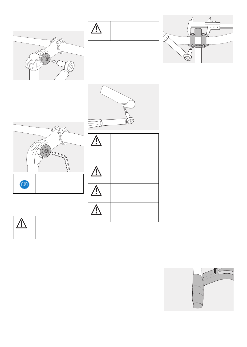
7. Handlebar adjuster
The handlebar adjuster adjust the angle of the
stem without dismantling the handlebar controls.
Only components with a 25.4 mm clamp may be
combined with a handlebar adjuster with a
25.4 mm clamp diameter. The stem must not be
wider than 50 mm.
Remove the handlebar from the stem – “5.
Mounting the handlebar” on page 2 and mount
the handlebar adjuster so that it sits centrally in
the stem clamp. Only tighten the four screws
enough so that the handlebar turns.
Attach the clamping arms as close to the stem as
possible. The clamping arms can be pushed to a
maximum of 55 mm apart.
After adjusting the angle, secure the clamping
arms with clamping bolts. For maximum torque,
refer to the information on the component.
The handlebar must be positioned in the middle
between the two clamping arms. The brake
levers and shifters must be easy to reach.
Tighten the bolts handlebar clamp until the top
and bottom clamping slots are the same width.
Tighten the bolts alternately to the lower
recommended torque limit. For maximum torque,
refer to the information on the component.
8. Adjusting the inclination of the
handlebar grips and brake levers
Adjust the handlebar so that the wrists are
relaxed and not twisted outward too much.
Adjusting the brake levers is a jobs for a specialist.
Adjusting the handlebar position by twisting the
handlebar
Loosen the hex screw on the stem 1–2 turns.
Turn the handlebar to the desired position. The
handlebar must be clamped in the middle by the
stem. Retighten the bolts to the prescribed torque
value.
To adjust the brake levers and shifters, loosen
the hex screw on the grip binders. Twist the grip
on the handlebar. Sit on the saddle and place a
finger on the brake lever. Your hand must form a
straight line with your lower arm. Retighten the
bolts to the prescribed torque value.
9. Grips and bar tape
Mounting the grips
Keep the grips and bar tape in good condition
and free from grease or the like.
Conventional grips are usually pushed onto the
oil and grease-free handlebars. The easiest way
to mount these grips is with compressed air.
Grips with screw attachments are pushed on and
secured to the handlebar with screws. For
maximum torque, refer to the information on the
component.
Grips with open ends should be sealed with the
included bar plugs.
Wrapping the bar tape
The handlebar must be free of dirt and oil.
Start at the open handlebar end. Allow the tape to
overhang one turn. Wrap the tape diagonally
upward, so that a third of the tape overlaps. Hold
the tape under tension during this process and
Note
Never adjust the heat nut of
the headset bearing when
adjusting the stem.
Danger
Never ride a bicycle whose
stem has been pulled out
beyond the maximum
extension height mark.
Danger
Do not mount or use bar ends
on MERIDA carbon
handlebars.
Danger
If the bar ends do not clamp
properly to the contact
surfaces despite the use of
MERIDA carbon paste, the
components might not be
compatible.
Danger
Components must be
tightened to the specified
torque.
Danger
Clamping bar ends to an
unsuitable handlebar may
result in a break.
Danger
Braking distance increases
when you are riding with your
hands on the bar ends.
3

remove the paper backing from the self-adhesive
side as you go.
Place a single piece of tape on the brake lever so
that the handlebar is completely covered.
Continue wrapping the tape evenly until you
reach the thicker handlebar cuff. Cut the tape
diagonally with scissors for a straight finish.
Secure the tape with the enclosed adhesive strip.
Push the overhanging bar tape into the open end
of the handlebar and close it with a bar plug..
10. Cleaning and care
Clean the components regularly with water and a
soft cloth. For stubborn dirt, use dish soap with
warm water. Do not use harsh cleaning agents
such as thinners.
After the components have dried, you should rub
the metallic surfaces and carbon with hard wax at
least two times per year. Polish the components
once the wax has dried.
11. Maintenance
Check the torque values of all bolts after the first
100–300 km (60–180 miles), and then again
every 2,000 km (1,200 miles).
12. Warranty and guarantee
Statutory warranty rights apply within the first two
years. This regulation only applies in states that
have ratified the EU bill. Bar tape and grips are
subject to natural wear, depending on use and
external conditions.
We also grant a manufacturer’s guarantee on all
MERIDA components, except grips and bar tape,
(from the date of purchase, to the first purchaser)
of 5 years on material and workmanship.
Should any defects occurs, contact your
MERIDA dealer. In a guarantee case where the
respective higher-quality model is unavailable,
MERIDA INDUSTRY CO., LTD. reserves the
right to deliver the respective current successor
model in the available color.
Assembly and/or conversion costs and any
accessories will not be refunded in a guarantee
case.
The manufacturer guarantee is only valid for the
first purchaser upon presentation of proof of
purchase with the purchase date, dealer
address, and model name.
The intended use is a prerequisite for the
guarantee. The guarantee does not cover labor
and transportation costs, or any follow-up costs
caused by defects.
Competition use in the context of road races,
triathlon, or the MTB sections of cross-country
races are covered by the guarantee.
Other visible fall damage resulting from jumps or
other types of overstress is likewise not covered
by the guarantee. The guarantee does not cover
damage caused by wear, neglect, crashes,
overstressing caused by overloading, improper
installation and care, or the modification of
components.
In the interest of a long life and durability of the
components, the manufacturer’s installation
instructions and the prescribed maintenance
intervals must be adhered to exactly. Failure to
comply with the installation instructions and
inspection intervals will void the guarantee.
Handlebar grips and tape wear during use.
Regular cleaning and care have a positive impact
on wear.
13. Technical specifications
Handlebar
Clamp area cuff
MTB, Cruiser, Traveller: 25.4 mm
Road bike: 26.0 mm
Oversized road bike and
MTB: 31.8 mm
Handlebar clamp max.
torque:
2-bolt stem: 8 Nm
4-bolt stem: 6 Nm
Bar ends
Clamp area: 22.2 mm
Torque: 6–8 Nm
Aheadset®stem
Handlebar clamp area:
MTB, Cruiser, Traveller: 25.4 mm
Road bike: 26.0 mm
Oversized road bike and
MTB: 31.8 mm
Steerer tube clamp area: 28.58 ± 0.05 mm
Torque:
Steerer tube clamp: 5–7 Nm
Handle bar clamp
2-bolt stem: 6–8 Nm
4-bolt stem: 5–6 Nm
Conventional stem
Handlebar clamp area: 25.4 mm
Steerer tube
internal diameter 25.4 mm
Handlebar clamp torque:
2-bolt: 15 Nm
Steerer tube clamp:: 20–22 Nm
Adjustment bolt adjustable
conventional stems: 10 Nm
Handlebar adjuster
Handlebar clamp area: 25.4 mm
Stem clamp area: 25.4 mm
Handlebar clamp: 8–10 Nm
Stem clamp: 8–10 Nm
Reducing sleeves
Handlebar clamp diameter:
from 31.8 mm to 26.0 mm
from 31.8 mm to 25.4 mm
Tube diameter:
from 28.6 mm to 25.4 mm (1 1/8” to 1”)
Spacer
For 1 1/8”
Available in heights of 2, 3, 5, 10 and 15 mm
Handlebar grips, Screw-on model
Torque: 2–3 Nm
Note
When cleaning, pay attention
to any damage to the
materials.
Note
If there is any doubt, always
adhere to the values specified
on the component.
If you have any questions, please contact:
MERIDA INDUSTRY CO., LTD.
P.O. Box 56
Yuanlin Taiwan R.O.C.
Phone: +886-4-8526171
Fax: +886-4-8527881
www.merida-bikes.com
5th Edition, February 2017
© No part of this document may be reprinted,
translated, reproduced, or otherwise used, e.g.
on electronic media without prior written consent.
Graphics, text, and design
2W Technische Informations GmbH & Co.KG
www.2wgmbh.de
4
Table of contents
Other Merida Bicycle Accessories manuals


