EN
EN
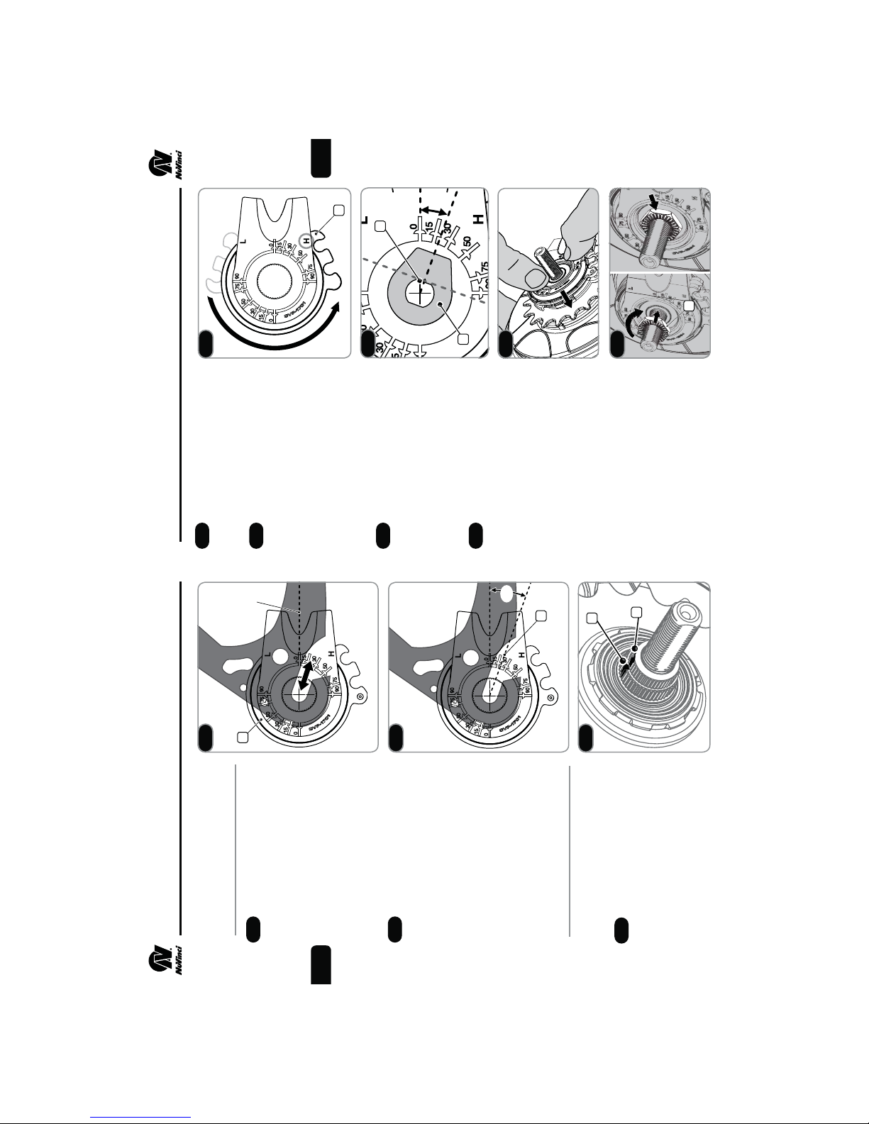
Install the NuVinci N360 CVP
into a vice or xture as shown,
clamping on the left hand axle ats.
fIf a vice is not available,
installation in the bicycle frame
is possible, tightening only the
left hand side no-turn washer
and axle nut to allow rotation
of the hub interface.
While driving the CVP clockwise
with the sprocket (1), rotate the
hub interface (2)
counter-clockwise
toward
the full overdrive (H) position
until a rm stop is felt. Repeat this
rotation 2-3 times by driving the
CVP clockwise and rotating the hub
interface back and forth, ending at
a rm stop toward (but likely not at)
the full overdrive (H) position.
fThe indicated position of the
hub interface is unimportant
in this step.
fWhen in full overdrive, the
hub/wheel should rotate
approximately 1.8-2 times
for every 1 rotation of the
CVP sprocket.
When full overdrive is found,
remove the hub interface per
Step 5.5.
Check to make sure the mark on
the spline nut and shift driver align
per Step 5.6.
Install hub interface per Steps 2.4
through 2.10.
At all times while rotating
the wheel, sprocket, or hub
interface, be careful not to
catch or pinch ngers.
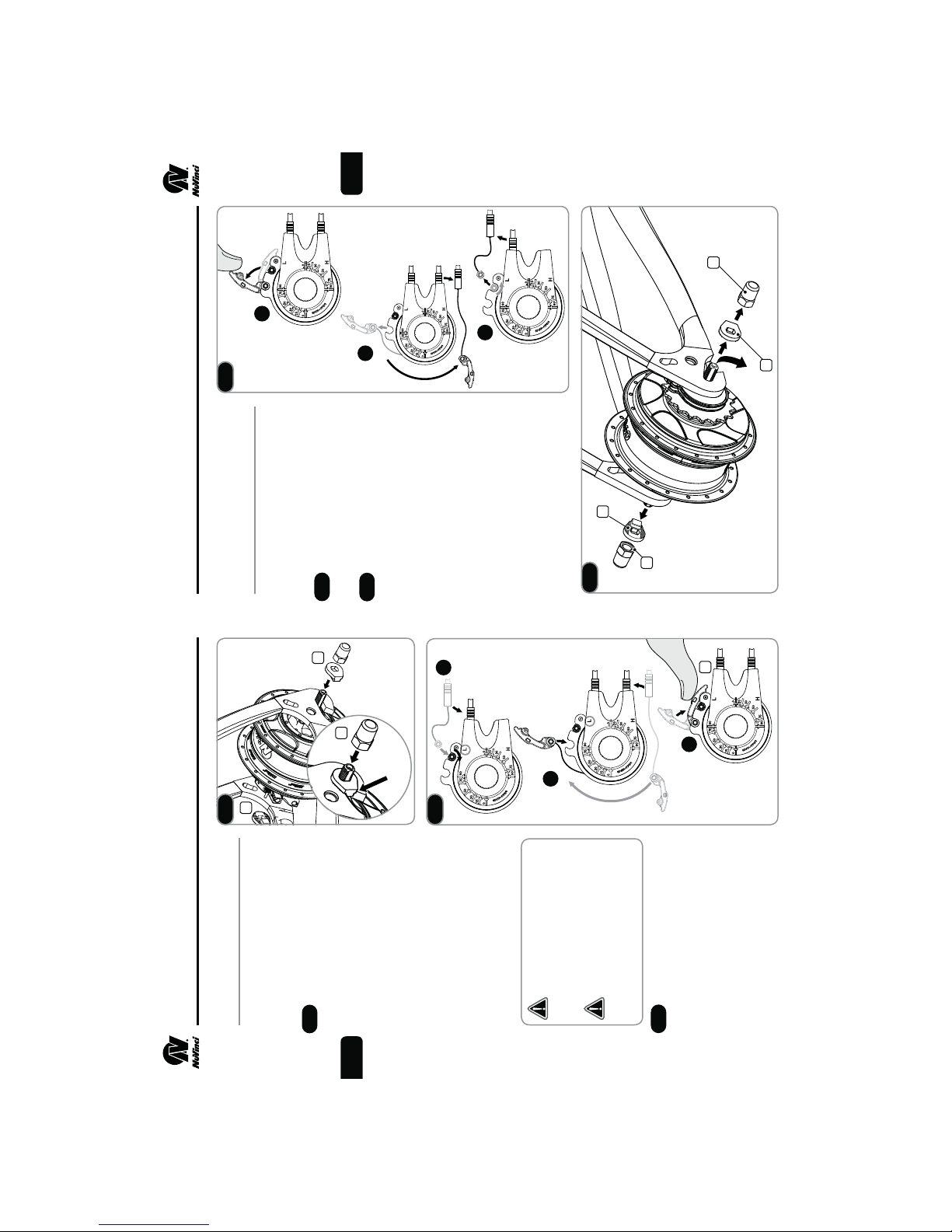
5. SERVICE INSTRUCTIONS
Remove the rear wheel per Section 3.
Remove the hub interface per Step 5.5.
Reference the Exploded Diagram
on Page 22. Remove the sprocket
snap ring (12), sprocket spacer
(13, if installed), and sprocket (14).
Remove the snap ring (15) on
the shift driver, and remove the
freewheel assembly (16).
fIf servicing or replacing,
use a medium-weight oil or
lightweight water-resistant
grease and check function.
Remove the interior snap ring
(17), needle bearing (18), and RH
shield (19) if these components are
being replaced.
Install the serviced / new free-
wheel components according to
the Exploded Diagram on Page 22.
Install sprocket and hub interface
per Section 2.
Install the rear wheel per Section 3.
Servicing or Replacing
Freewheel
Set the NuVinci N360 CVP
in full overdrive with the front
shifter or hub interface prior to
removal.
5. SERVICE INSTRUCTIONS
17 18
5.8
5.9
5.10
5.11
17
18
19
16
15
5.10
5.11
5.8
5.9
1
2
fReference Exploded Diagram P.21